
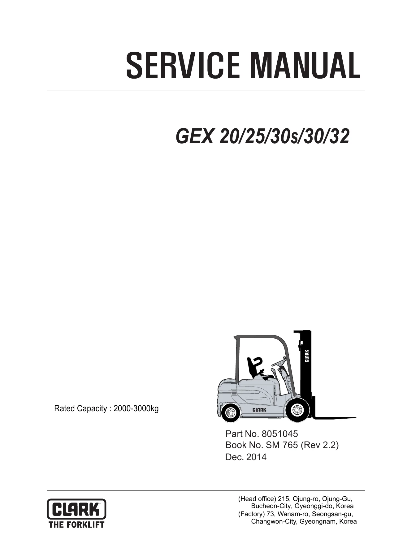
Clark GEX20 GEX25 GEX30s GEX30 GEX32 Electric Forklift Service Manual SM765 Rev 2.2 PDF
Original price was: $59.95.$39.95Current price is: $39.95.
Complete Clark GEX20, GEX25, GEX30s, GEX30 and GEX32 electric forklift service manual (SM765 Rev 2.2). 417-page PDF covering AC drive and pump motors, ZAPI controllers, drive axle, wet disc brakes, steering, hydraulic lift circuit, uprights, wiring diagrams and full torque specifications.
Description
Clark GEX20 GEX25 GEX30s GEX30 GEX32 Electric Forklift Service Manual — SM765 Rev 2.2
This is the complete Clark GEX20, GEX25, GEX30s, GEX30 and GEX32 electric forklift service manual, published under book number SM 765 (Rev 2.2) dated December 2014 and part number 8051045. At 417 pages, it covers the full range of maintenance, troubleshooting, overhaul and specification data for these 80-volt AC electric counterbalance trucks — from battery service and ZAPI motor controllers through to the drive axle, wet disc brake system, steering axle, hydraulic control valve, tilt cylinders and upright assemblies.
File Details
- Manual type: Service Manual
- Brand: Clark
- Models covered: GEX20, GEX25, GEX30s, GEX30, GEX32
- Language: English
- Page count: 417
- File format: PDF
- Document number: SM 765
- Revision: Rev 2.2
- Date: December 2014
- Part number: 8051045
Chapters Covered
- Group SA — Safe Maintenance
- Section 2 — Lifting, Jacking, and Blocking
- Section 3 — Towing
- Group PS — Periodic Service
- Group 12 — Battery
- Group 13 — Wiring, Switches, and Instruments
- Group 16 — Electric Motors
- Group 17 — Electrical Contactors
- Group 19 — Motor Controls
- Group 20 — Drive Axle
- Group 22 — Wheels and Tires
- Group 23 — Brake System
- Group 25 — Steering Column and Gear
- Group 26 — Steering Axle
- Group 29 — Hydraulic Sump, Filters, and Pump
- Group 30 — Hydraulic Control Valve/Lift Circuit
- Group 32 — Tilt Cylinders
- Group 34 — Uprights
- Group 38 — Counterweight and Chassis
- Group 40 — Specifications
Safety and Handling Procedures (Groups SA, Lifting/Jacking/Blocking, Towing)
The manual opens with the safety signs and messages conventions used throughout, followed by detailed procedures for raising the drive wheels using the upright as a lever, raising the rear of the truck, raising the entire truck, and shipping tie-down instructions. The towing section covers approved solid-metal tow bar requirements, counterweight bolt torque of 450–500 N·m (332–369 ft-lb), and the caution that power steering will not operate on a disabled truck. These are the foundational procedures every technician needs before starting any major repair on a GEX truck.
Periodic Service (Group PS)
The planned maintenance program spans three sections: the maintenance schedule with recommended intervals (50–250 hours, 450–500 hours, 900–1000 hours, 2000 hours), the planned maintenance inspection procedures covering visual inspection, operational checks, test drive with load, lift mechanism checks, battery compartment inspection, motor transistor controls inspection, hydraulic compartment inspection, cleaning, air-cleaning, critical fastener torque checks, lubrication, hydraulic sump and filter service, drive axle fluid, and upright/tilt cylinder lubrication, plus the PM inspection form. This is the routine service backbone for keeping a GEX truck in production.
Battery Service (Group 12)
Battery removal, maintenance, maximum battery life practices, vent care, cleaning, charging, electrolyte handling, compartment cleaning, replacement batteries, installation, record keeping, and testing — including specific gravity tests with a temperature-corrected hydrometer (full charge at 1.260–1.300, recharge below 1.250, cell variation limit 0.015) and load tests (minimum acceptable reading 64 volts for an 80-volt battery). Safety coverage includes the required protective clothing, overhead hoist and insulated spreader bar procedures, and the explosive-gas warnings that govern battery service areas.
Wiring, Switches, and Instruments (Group 13)
This group contains the schematic electric circuit diagrams for standard trucks (IN-28374) and ELH option trucks (IN-38375), general electrical service tips including capacitor discharge procedure (200 ohm 10 watt resistor across the controller input posts for 10 seconds), wiring and cable routing illustrations for the main harness (SI-47202), cables (SI-47193), accessory harness (SI-47115), EE construction option (SI-48448) and cold storage option (SI-47781). It also covers the accelerator control switch and its program adjustment via handset, brake switches (service brake and parking brake) with adjustment procedures, seat switch operation with the 1.5-second time delay, and lift/tilt pump switches with lift pot programming. The instrument panel section explains the dash display layout, battery discharge indicator, hourmeter/speed display, message display, travel direction icon, error icon, and the full menu mode operation including password setup, model set, maintenance hour setting, speed display unit selection, and date/time setup.
Electric Motors and Contactors (Groups 16 and 17)
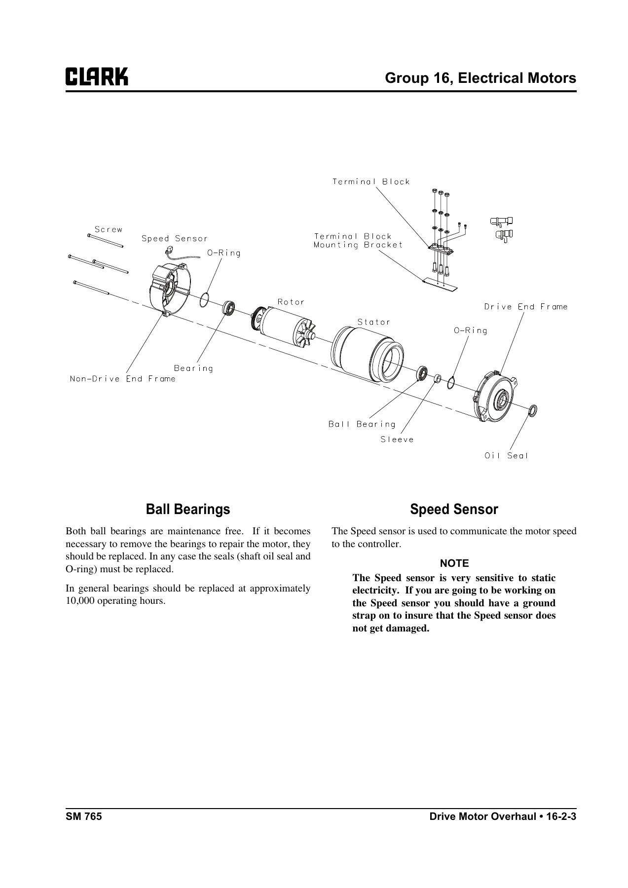
Complete specifications and overhaul procedures for the two identical 240 mm frame drive motors (149 mm rotor OD, 65 mm rotor ID, 44 rotor slots, 36 stator slots, 0.5 mm nominal air gap, 1800 RPM nominal speed, 275A stall current, Class F insulation, delta winding, 64 pulses/rev encoder) and the 200 mm frame pump motor (124 mm rotor OD, 46 mm rotor ID, 48 rotor slots, 36 stator slots, 0.4 mm nominal air gap, 2160 RPM nominal speed, 450A stall current, Class F insulation, delta winding, 64 pulses/rev encoder). The overhaul sections cover speed sensor replacement, encoder bearing replacement (every 10,000 hours or at disassembly), ball bearing service, and reassembly with silicone sealer at the cable exit. Group 17 covers the drive line contactor and pump line contactor with contact tip inspection and replacement procedures.
Motor Controls (Group 19)
The ZAPI dual AC controller architecture is documented in full: the master control drives the right motor, the slave drives the left, and a separate pump controller manages the lift/steer motor. Topics include control programming with the ZAPI handset (Clark part #8033636, minimum Release 3.07), tester menu functions for master, slave and pump controls, fault code diagnostics with over 75 codes listed with description and troubleshooting steps, and factory control settings tables for both traction and pump controls across Turtle, Economy, Normal and Power modes. The description explains regenerative braking, release braking, pedal braking, inversion braking, stop-on-ramp, steering time delay, static return to off (SRO), thermal protection thresholds, battery discharge indication with lift lockout at 10%, and the full CAN-BUS communication between controllers and dash display. Pin-out tables for the master control (A1–A8, B1–B8, C1–C35), hydraulic AC3 pump control (A1–A35, B1–B8), and encoder wiring are included.
Drive Axle (Group 20)
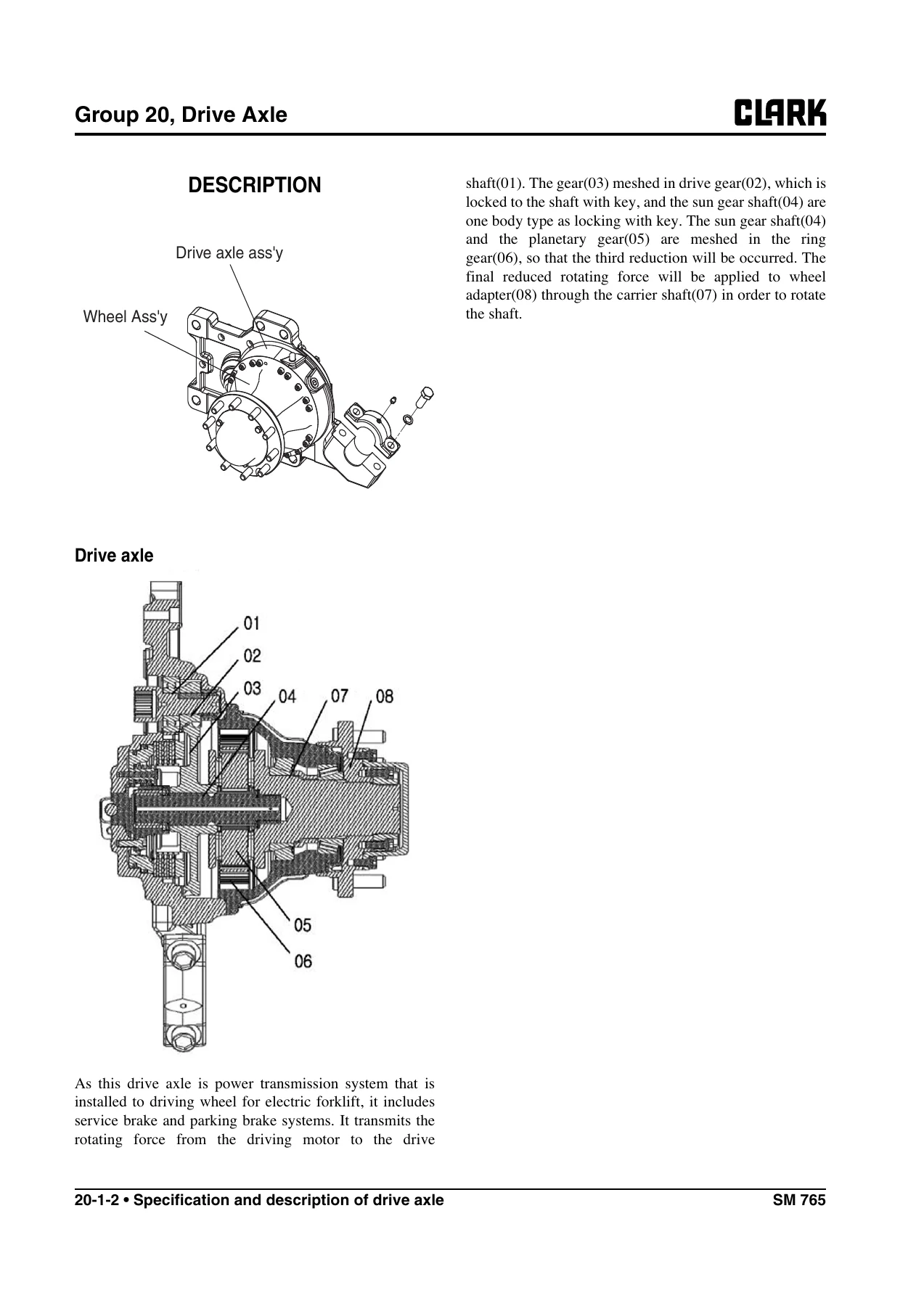
Specifications include a 26:1 reduction ratio, 1.0 liter oil capacity, Mobil #424 oil, wet brake type, 1.95cc × 2 required service brake flow, 0.85–0.90 mm service brake setting stroke, and a weight of 62 kg excluding oil. The group covers troubleshooting (truck won’t move, overheated axle), general operation and planetary gear description (first reduction at drive gear, second at sun gear shaft, third at planetary/ring gear), disassembly and reassembly of the drive axle, service brake disassembly (reaction plates, brake discs, return springs, piston), bearing boss disassembly, parking lever and drive shaft disassembly, master hinge and brake fitting removal, axle end disassembly including carrier shaft and wheel sub-assembly, and the adjustment procedures for hub taper roller bearing preload (3920 kgf·cm / 285 lbf·ft lock nut torque, push-pull gauge spec 12–15 kgf·cm) and brake disc gap (0.85–0.9 mm specification with shim selection table).
Wheels and Tires (Group 22)
Pneumatic and cushion tire specifications with drive tire inflation at 800 kPa (116 psi) and steer tire inflation at 1000 kPa (145 psi). Drive wheel mounting nut torque is 180–210 N·m (133–155 ft-lb) for 1-piece black nuts; steer wheel lug nuts torque to 225–250 N·m (165–185 ft-lb). The group includes OSHA-compliant multi-piece rim servicing warnings, pneumatic tire maintenance precautions, wheel dismounting and remounting, wheel disassembly and tire removal, tire replacement and wheel reassembly, directional tread mounting orientation, filling tires with air or nitrogen, and checking/adjusting tire pressure.
Brake System (Group 23)
Specifications list a wet disc service brake with hydraulic fluid RANDO HD32 or NUTO H32 per CLARK MS-68 (CLARK #2776239), no pedal freeplay, and a parking brake that holds a rated load on a 15% grade. The group covers service brake troubleshooting (pedal drops to floor, spongy pedal, sticking/dragging brakes, excessive effort), brake pedal linkage adjustment (pedal height 25 mm via stop bolts, torque 20–25 N·m), brake bleeding procedure, pedal and master cylinder service including freeplay adjustment (depress pedal 4–6 mm), and parking brake service with cable adjustment and interlock/indicator switch positioning.
Steering Column and Gear (Group 25)
Hydrostatic power steering with load sensing and dynamic signal neutral circuit. Relief pressure setting is 10,000 kPa (1,450 psi), checked annually or every 2,000 hours. The group covers steering system troubleshooting (no steering, hard steering, high handwheel turns, free-spinning handwheel, jerky steering, wrong direction, kickback, slow response, chatter, noise), steering column and component removal and replacement (hand wheel, horn contact ring, directional control assembly, column tilt lock assembly, steering gear and lower steering column), relief pressure check and adjustment via the gauge port on the main pump, and complete steering gear overhaul covering the meter (gerotor) end, control end, check ball seat, spool and sleeve assembly, centering springs, seals and reassembly torque values.
Steering Axle (Group 26)
Steer axle specifications include 10,000 kPa (1,450 psi) relief pressure, double-acting piston-type steer cylinder, 100° maximum inside turning angle, 70° maximum outside turning angle, bearing grease Grade No. 2 EP multi-purpose per Clark MS-107C, steer axle mounting bolts 170–190 N·m (125–140 ft-lb), and cylinder-to-axle mounting bolts 280–320 N·m (205–234.5 ft-lb). The group covers wheel bearing maintenance and adjustment (27–31 N·m initial torque, 29.3–33.9 N·m final torque with cotter pin), steering axle removal and installation, steering axle overhaul including kingpin and knuckle bearing service (50–60 N·m initial kingpin torque, 30–35 N·m final with new cotter pin), steering cylinder removal and installation, steering cylinder overhaul with operational pressure test at 13,790 kPa (2,000 psi) with no leakage, and pivot-turn steering axle maintenance for the 75° outside turning angle variant.
Hydraulic Sump, Filters, and Pump (Group 29)
The integral gear-type pump and motor assembly draws from a 24-liter (6.3-gallon) usable oil sump using CLARK MS-68 hydraulic fluid. Filtration is a disposable 25-micron return line filter, 100-mesh suction line screen, and 10-micron filter cap/breather. The group covers fluid level checks every 8–10 hours, fluid and filter changes every 2,000 hours or annually, sump breather maintenance, pump troubleshooting (noisy pump, no delivery, failure to build pressure, low output, foaming fluid, overheating, external leakage), and main hydraulic pump removal and installation including the suction line, pressure line, and mounting fasteners.
Hydraulic Control Valve/Lift Circuit (Group 30)
Specifications include main relief valve setting 20.6–21.1 MPa (2,988–3,060 psi) at rated flow, auxiliary relief 13.7–14.2 kPa (1,987–2,060 psi), rated flow 70 L/min (18.5 gpm), and maximum pressure drops for the lift spool (inlet to cylinder 1,471 kPa / 213 psi, cylinder to outlet 981 kPa / 142 psi), tilt spool, and auxiliary spools. The group covers the open-center parallel-circuit modular valve design with lift, tilt, and optional auxiliary sections, a counterbalance valve integral to the tilt section, adjustable pressure-compensated flow controls, hydraulic schematics for normal valve and ELH valve, system troubleshooting (no lift/tilt/aux, slow/jerky action, foaming, overheating, load won’t hold, spools don’t return to neutral, no relief action, load drops), pressure checks and adjustments via the gauge port on the main valve, and control valve removal and replacement including linkage disassembly and reassembly.
Tilt Cylinders (Group 32)
Double-acting tilt cylinders with maximum operating pressure 21,000 kPa (3,000 psi). Tilt ranges by mast type are tabulated: STD uprights at 5° back / 6° forward, TSU at 5° back / 6° or 3° forward depending on MFH, and QUAD at 3° / 3°. The group covers tilt cylinder drift test (0.5° / 3.9 mm at 1 minute, 5° / 39 mm at 10 minutes at 50°C / 122°F), drift causes and remedies, racking check and forward/backward adjustment, removal and replacement with base pin and rod-end pin lock plate torques of 40–45 N·m (30–33 ft-lb), rod-end yoke clamp bolts at 166–193 N·m (122–142 ft-lb), and complete tilt cylinder overhaul including gland removal with hook wrench, seal replacement, and gland torque of 60±6 kgf·m.
Uprights (Group 34)
The largest single group in the manual. Upright weights range from approximately 341 kg (753 lb) to 971 kg (2,140 lb) without carriage; carriage weights 126–150 kg (278–330 lb); forks 50–106 kg each. Standard uprights use two lift cylinders; TSU and Hi-Lo use a primary (center-mounted) piston cylinder plus two secondary cylinders. The group covers upright specifications and description, troubleshooting (upright noise, no lift/tilt/aux, load won’t reach max height, sluggish lift or lower, load bounce, mis-staging on TSU lifting and lowering, external leakage on primary and secondary cylinders, oil leak at top of lift cylinder, unsatisfactory drift test), upright inspection including basic visual and extended inspection, fork alignment, fork bending check, fork fatigue, fork wear and heel wear (10% maximum reduction, Clark part #1803641 caliper), fork hanger and carriage fork bar wear, fork latch and carriage fork stops, lift chain wear (3% elongation limit, 305 mm / 12 in segment measuring 315 mm / 12.36 in indicates replacement), chain length and tension checks, carriage and upright weldment inspection, roller side clearance checks and shim adjustments with the full Roller Side Clearance Chart, internal thrust roller adjustment, oversize roller identification, carriage roller shimming and upright roller shimming, upright roller removal and reassembly, cylinder removal and shimming procedures for lift and secondary cylinders, primary cylinder removal for Hi-Lo and TSU, complete cylinder overhaul with check valve service and gland torque (135 N·m / 100 ft-lb primary, 100 N·m / 75 ft-lb lift and secondary), chain inspection and adjustment with fork-to-ground clearance 10–20 mm (0.40–0.80 in), chain lubrication, chain removal and replacement, fork and carriage removal and replacement, and upright removal and replacement including trunnion ring bolts and tilt cylinder rod-end pins.
Counterweight and Chassis (Group 38)
Counterweight mounting bolts torque to 340–380 N·m (251–280 lb-ft) on the lower bolts or 450–500 N·m (332–369 ft-lb) per the removal/installation section. Counterweight weights by model: GEX20 560 kg (1,235 lbs), GEX25 760 kg (1,675 lbs), GEX30 720 kg (1,587 lbs), GEX30s 985 kg (2,171 lbs), GEX32 985 kg (2,171 lbs). The group covers counterweight removal and installation (eyebolt rated 1,193 kg / 2,630 lb, overhead hoist required), overhead guard removal and installation (eight mounting bolts torqued 88–95 N·m / 65–70 ft-lb), floor plate removal, operator seat deck and hood removal/reinstallation, and seat mounting fastener torques.
Specifications (Group 40)
Nameplate and decal locations with the actual decal illustrations (Operator Safety Warning, Hand Safety, Keep Away from Forks, Battery Disconnect, Polarity Warning, Electric Truck Warning), general specifications including weights and performance data, critical fastener torque specifications (drive axle-to-frame 450–500 N·m, drive wheel lug nuts 180–210 N·m, steer axle mounting 170–190 N·m, steer wheel lug nuts 225–250 N·m, steering handwheel retaining nut 40–45 N·m, tilt cylinder yoke clamp 170–190 N·m, tilt cylinder pin retainer 40–45 N·m, counterweight mounting 450–500 N·m), drift limits for lift and tilt cylinders (fork downdrift not to exceed 100 mm / 4 in in 10 minutes, tilt cylinder drift not to exceed 5° in 10 minutes), lift and lowering speeds by model and upright type, brake system specifications, drive axle fluid specification (Mobil #424), steering column and gear specifications, steer axle specifications, hydraulic sump/filters/pump specifications, tilt cylinder specifications, upright specifications, and the hydraulic fitting tightening procedure.
What This Manual Enables You to Do
Armed with this Clark GEX20/25/30s/30/32 service manual, you can diagnose and repair the full electric drivetrain — dual AC traction motors, the lift/steer pump motor, the ZAPI master/slave/pump controllers, the drive axle with integral wet brake, the steering axle and cylinder, the main hydraulic control valve, tilt cylinders, and the upright with its lift chains, rollers, and cylinders. You can perform the complete periodic maintenance schedule, interpret every fault code the dash display can show, program the controllers with a handset, adjust brake pedal freeplay, set the steering relief pressure, shim the upright rollers to correct clearance, and torque every critical fastener to the correct specification. The wiring diagrams and hydraulic schematics let you trace circuits and flows without guessing, and the troubleshooting tables in every group give you a structured path from symptom to cause to repair.
IMAGES PREVIEW
Get the Complete GEX Service Manual — Instant PDF Download
This is the same 417-page service manual used by professional forklift technicians to maintain and repair the Clark GEX20, GEX25, GEX30s, GEX30 and GEX32 electric trucks. Whether you’re chasing an intermittent fault code, rebuilding a drive motor, replacing upright chains, or setting up a planned maintenance program, the correct procedures and specifications are all here in one document. The PDF downloads instantly after payment — no shipping, no waiting, no physical media. Open it on any laptop, tablet, or smartphone in the workshop, print the pages you need for the job, and keep the full manual on file for the next repair. Having the actual Clark service manual for your GEX truck is the difference between guessing at a repair and doing it right the first time.
Reviews
There are no reviews yet.