
Commander 114B/114TC Maintenance Manual – Complete PDF Service & Repair Guide
Original price was: $34.95.$21.95Current price is: $21.95.
Complete 324-page Commander 114B/114TC maintenance manual covering the Lycoming IO-540-T4B5 and TIO-540-AG1A powered models. Hydraulics, power plant, fuel, landing gear, flight controls, instruments, heating, and the 28-volt DC electrical system, with rigging values, pressures, torque figures, and troubleshooting charts.
Description
Commander 114B/114TC Maintenance Manual – 324-Page PDF for Both Models
This Commander 114B/114TC Maintenance Manual is the complete service document for the Commander Aircraft Company Model 114B and Model 114TC, the low-wing single-engine business and pleasure aircraft built around the Lycoming IO-540-T4B5 and TIO-540-AG1A engines. Across 324 pages and ten sections, this Commander 114B/114TC maintenance manual provides the procedures, dimensions, torque values, pressure settings, inspection intervals, and system descriptions needed to service, troubleshoot, and repair both airframes.
Whether you are maintaining a normally aspirated 114B or a turbocharged 114TC, this Commander 114B/114TC maintenance manual is written to be used in the hangar rather than on a shelf. It covers everything from day-to-day servicing and ground handling through hydraulic landing gear operation, fuel injection, turbocharger control, flight control rigging, instrument and pitot-static systems, cabin heating and ventilation, and the 28-volt DC electrical system.
File Details
- Manual type: Maintenance Manual
- Manufacturer: Commander Aircraft Company
- Models covered: Commander 114B, Commander 114TC
- Language: English
- Page count: 324 pages (as stated in the List of Effective Pages)
- File format: PDF
- Revision: Revision A
- Original issue: February 1993; Revision A issued May 1996
Chapters Covered
- Section 1 – General Information: General Description, Principal Dimensions, Fuselage and Wing Stations, Aircraft Structures, Aircraft Systems
- Section 2 – Servicing: Ground Handling, Cold Weather Operation, Ground Emergency Procedures, Ground Operation of Engine, System and Component Servicing, Inspection, Airframe Maintenance
- Section 3 – Hydraulics: General Description, General Maintenance Practices, Hydraulic System Components, Trouble Shooting
- Section 4 – Power Plant and Propeller: Ignition System, Induction Air System, Fuel Injection System, Oil System, Turbocharger System (Model 114TC), Exhaust System, Cooling System, Engine Controls, Engine Accessories, Engine Change, Engine Mount and Cowling, Engine Conditioning, Propeller, Trouble Shooting
- Section 5 – Fuel System: General Description, Maintenance Precautions, Subsystems and Components, Fuel Line Maintenance, Trouble Shooting
- Section 6 – Landing Gear, Wheels and Brakes: Main Landing Gear, Nose Landing Gear, Landing Gear Position Indicators and Warning System, Wheels and Brakes, Trouble Shooting
- Section 7 – Flight Controls: Control Column, Ailerons, Wing Flaps, Rudder, Elevators, Elevator Trim Tabs, Aileron-Rudder Interconnect, Control Surface Balancing, Trouble Shooting
- Section 8 – Instruments: Instrument System Maintenance, Flight Instruments, Engine Instruments, Other Instruments, Stall Warning System
- Section 9 – Heating and Ventilation: Heater Operation, Ventilation System
- Section 10 – Electrical System: Power Distribution, Wiring Diagrams Index
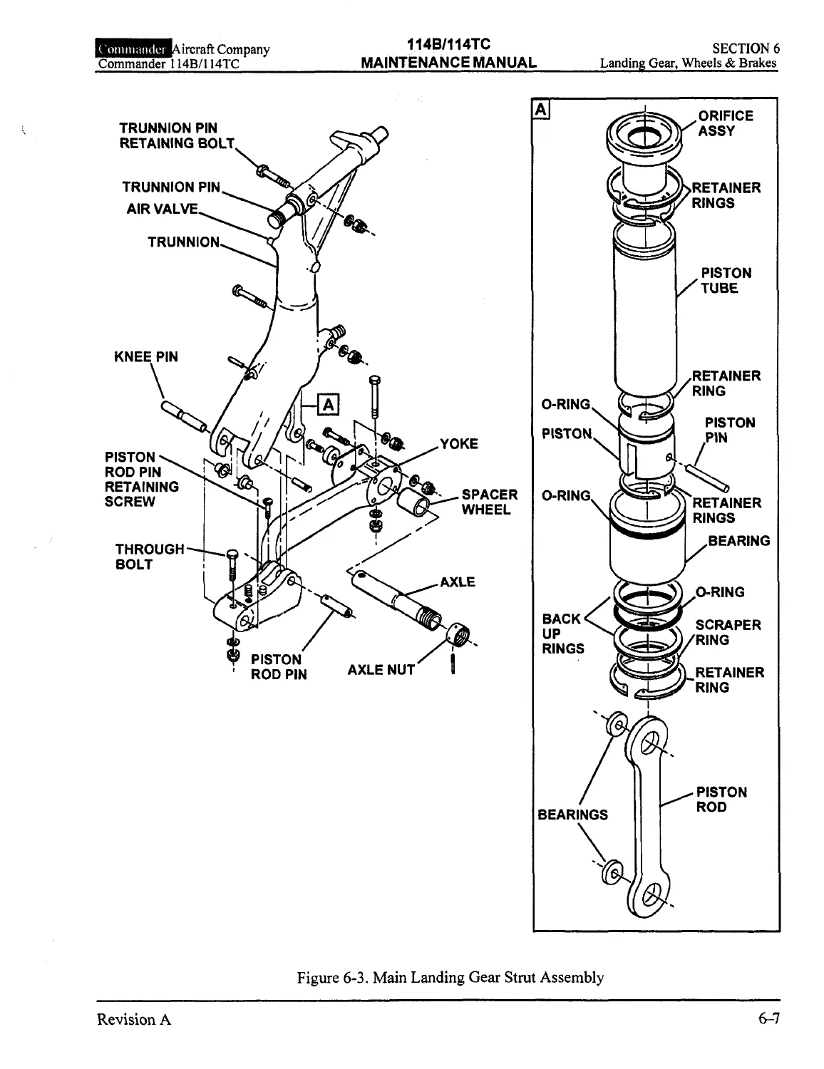
Each section is further divided into focused sub-chapters. The Power Plant and Propeller section, for example, walks through magneto removal, installation and timing, fuel injection servo regulator adjustment, oil cooler service, turbocharger and wastegate removal for the 114TC, exhaust system repair, baffle installation, engine control rigging, engine change, and propeller governor rigging. The Landing Gear section covers main and nose gear oleo disassembly and reassembly, strut servicing, shimmy dampener service, nose wheel steering rigging, squat switch adjustment, wheel and brake overhaul, and brake bleeding.
What This Commander 114B/114TC Maintenance Manual Gives You
Because the Commander 114B/114TC maintenance manual was written around the actual airframe and systems, every procedure is tied to a specific model, serial range, or system. It distinguishes between the two engine installations throughout – the normally aspirated Lycoming IO-540-T4B5 in the 114B and the turbocharged Lycoming TIO-540-AG1A in the 114TC – and separates serial-number effectivity so you apply the correct values to your airframe. The manual identifies 114B S/N 14541 through 14572, S/N 14573 and subsequent, S/N 14625 and subsequent, and S/N 14628 and subsequent configurations, plus 114TC S/N 20001 and subsequent.
What separates a working Commander 114B/114TC maintenance manual from a generic aircraft reference is the level of system detail. Hydraulic power pack pressure settings are given (1600-1700 psi for gear up, 450-550 psi for gear down, gear up relief 1750-2100 psi, gear down relief 600-800 psi, thermal relief 2025-2425 psi), strut inflation pressures are specified (main gear 395 +/-10 psi, nose gear 120 psi), tire pressures are listed (main 39 psi, nose 50 psi), engine oil capacities are defined (8 quarts for 114B, 10 quarts for 114TC), and control surface travel limits are tabulated (aileron up 23.5 +/-3.5 degrees, down 9 +/-2 degrees; elevator up 30 +/-2 degrees, down 13 +2/-1 degrees; rudder 25 +/-2 degrees each side of neutral; flap down 35 +0/-2 degrees).
The Commander 114B/114TC maintenance manual also includes rigging procedures for every control system, with cable tensions, temperature conversion charts, and control surface balancing instructions. There are step-by-step procedures for the hydraulic emergency free-fall test, landing gear operational checks, pitot-static leak tests, fuel quantity transmitter calibration, elevator trim jackscrew service, and aileron-rudder interconnect rigging. These are the tasks that separate a well-maintained Commander from one that develops rigging drift, brake drag, or gear warning faults.
Beyond routine procedures, the manual contains extensive troubleshooting guidance. Each major system closes with a trouble-shooting chart pairing symptoms with probable causes and remedies. Hydraulic gear faults, fuel flow problems, turbocharger output faults on the 114TC, brake drag, instrument and vacuum failures, and flight control resistance are all broken down so a technician can isolate a fault before replacing parts.
Models, Engines, and Systems Covered
- Commander 114B – Lycoming IO-540-T4B5, 260 hp, normally aspirated, six-cylinder horizontally opposed, fuel injected
- Commander 114TC – Lycoming TIO-540-AG1A, 270 hp, turbocharged, six-cylinder horizontally opposed, fuel injected
- Propeller – McCauley B3D32C419/82NHA-5 all-metal, constant-speed, 3-blade
- Systems covered – Hydraulic, power plant, fuel, landing gear, wheels and brakes, flight controls, instruments and vacuum, heating and ventilation, electrical
Who This Manual Is For
Aircraft owners who do their own maintenance, A&P mechanics maintaining a Commander 114B or 114TC, and shops performing annual inspections will find this Commander 114B/114TC maintenance manual directly usable. The procedures assume access to standard aircraft tooling, but the manual identifies where special tools, service instructions, or manufacturer bulletins are referenced, so nothing is left to guesswork. The wiring diagram index at the end of Section 10 points to individual system schematics for power and starter, landing gear, engine and flight instruments, interior lighting, exterior lighting, equipment, phone/mic jacks, and the electric cowl flap.
Because the manual is built around the aircraft’s serial numbers, it stays accurate across production changes. If you know the serial number of the Commander you are working on, you can go straight to the correct procedure and the correct pressure, torque, or travel figure without filtering out procedures that apply to a different configuration.
Get the Complete Commander 114B/114TC Maintenance Manual as a PDF
This Commander 114B/114TC maintenance manual gives you the complete service reference for both models in one PDF. You can diagnose a hydraulic gear fault, service a strut, set aileron and rudder travel, adjust a turbocharger density controller, balance a control surface, bleed brakes, or run a pitot-static leak test using procedures written by the aircraft’s engineering department and matched to the exact serial range you are working on. Correct procedures and accurate specifications are what keep these aircraft within rigging tolerances and safe to fly.
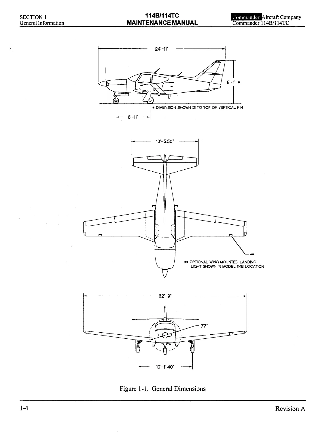
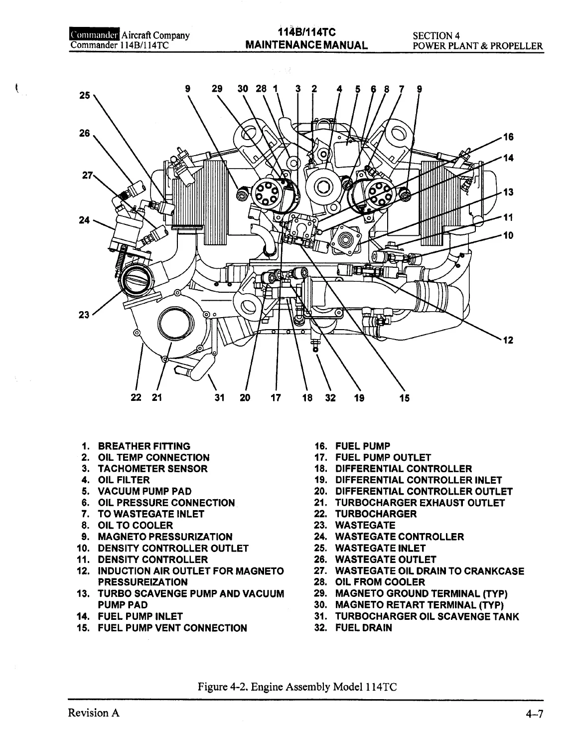
IMAGES PREVIEW
Delivered as an instant PDF download after payment – no shipping, no waiting. Read it on a laptop, tablet, or phone, print the sections you need for the hangar, and keep the full Commander 114B/114TC maintenance manual at hand for every job on your 114B or 114TC.
Reviews
There are no reviews yet.