Copystar CS-1820 Copier Service Manual – PDF DOWNLOAD
Original price was: $95.00.$18.95Current price is: $18.95.
Official Copystar CS-1820 digital copier service manual (Part 2GM70940) published March 2005. Comprehensive 274-page technical manual covering 18 ppm multifunctional copier with optional fax system. Includes complete specifications, installation procedures, maintenance modes, troubleshooting guides, electrical schematics, mechanical diagrams, assembly/disassembly instructions, and parts catalogs. Essential repair documentation for service technicians maintaining Copystar desktop copying systems.
Description
Copystar CS-1820 Copier Service Manual Fax System Digital MFP Repair Guide PDF DOWNLOAD
DESCRIPTION
Complete Copystar CS-1820 Digital Copier Service Manual
This is the official service manual (Part Number 2GM70940) published by Copystar (a Kyocera Technology division) for the CS-1820 digital copier with optional fax system, released March 2005. This comprehensive 274-page professional service manual provides complete technical documentation for installation, maintenance, troubleshooting, and repair of the CS-1820 desktop multifunctional copier system.
📋 File Details
- Manual Name: Copystar CS-1820 Service Manual
- Part Number: 2GM70940
- Model: CS-1820 (Includes Fax System K)
- Manufacturer: Copystar (Kyocera Technology)
- Publication Date: March 2005
- Pages: 274 pages
- File Quality: High-resolution PDF (Letter size)
- File Size: 11.9 MB
- Language: English
📠 Copystar CS-1820 Specifications
General:
- Type: Desktop digital copier/multifunctional system
- Copying system: Indirect electrostatic system
- Copy speed: 18 copies per minute (A4/8.5″×11″ @ 100%)
- First copy speed: Approximately 9.5 seconds (A4, platen)
- Warm-up time: 20 seconds or less
- Low power mode recovery: 10 seconds or less
- Sleep mode recovery: 15 seconds or less
Original Handling:
- Platen: Sheets, books, 3D objects (max: folio/legal 8.5″×14″)
- Document processor (optional): Sheet-through feed
- Maximum original size: Folio/Legal (8.5″×14″)
Copy Paper:
- Cassette capacity: 250 sheets (80 g/m²)
- Paper weight: 60-105 g/m² (plain paper)
- MP tray capacity:
- 50 sheets @ 80 g/m²
- 25 sheets @ 120 g/m²
- 10 sheets @ 160 g/m²
- 1 sheet (transparency)
- Paper weight: 60-163 g/m²
- Special paper support: Transparencies, letterhead, colored paper, recycled paper (use MP tray)
Copy Sizes:
- Maximum: Folio/Legal (8.5″×14″)
- Minimum: A6R/5.5″×8.5″
Copy Speeds (100% magnification):
- Platen:
- A4/8.5″×11″: 18 copies/min
- A5: 10 copies/min
- 8.5″×14″: 15 copies/min
- Document processor:
- A4/8.5″×11″: 18 copies/min
Magnification:
- Manual mode: 50-200% in 1% increments
Optional Features:
- Document processor
- Expanding memory
- Fax system (K)
📚 Comprehensive Manual Contents
SAFETY PRECAUTIONS (Pages 1-8)
Safety Symbols and Warnings:
- DANGER – High risk warnings
- WARNING – Serious injury warnings
- CAUTION – Injury/property damage warnings
- Symbol explanations with pictograms
1. Installation Precautions:
- Power supply requirements and grounding
- Location requirements (avoid humidity, dust, heat sources)
- Ventilation requirements
- Anti-toppling device installation
- Toner/developer handling safety
- Customer safety instruction requirements
2. Maintenance Precautions:
- Power disconnection procedures
- Service manual compliance
- Safety mechanism bypass prohibition
- Correct parts specification requirements
- Thermostat/thermal fuse replacement warnings
- Laser unit disassembly warnings
- High-voltage charger handling
- Fixing unit burn prevention
- Thermistor and roller cleaning
- Wire harness routing precautions
- Post-maintenance verification checklists
- Grease and solvent handling
- Toner disposal safety
3. Miscellaneous Warnings:
- Drum handling precautions
- Toxic gas prevention
CHAPTER 1-1: SPECIFICATIONS (Pages 1-1-1 to 1-1-4)
1-1-1 Complete Technical Specifications:
- Copying system details
- Original specifications
- Paper specifications
- Magnification ranges
- Speed specifications
- Feed system capacities
- All operating parameters
1-1-2 Names of Parts:
- Main body component identification with detailed diagrams
- Operation panel layout with button/indicator descriptions
- Part location references
- Nomenclature for service procedures
CHAPTER 1-2: HANDLING PRECAUTIONS (Pages 1-2-1)
1-2-1 Drum Handling:
- Photoconductor drum care procedures
- Damage prevention
- Environmental sensitivity
1-2-2 Installation Environment:
- Temperature and humidity requirements
- Location restrictions
- Ventilation needs
CHAPTER 1-3: INSTALLATION (Pages 1-3-1 to 1-3-22)
1-3-1 Unpacking and Installation (16 pages):
- Step-by-step unpacking procedures
- Protective material removal
- Machine positioning
- Initial setup procedures
- Packaging material handling
1-3-2 Cable Connections:
- Network cable connection procedures
- Printer cable connection procedures
- Cable routing guidelines
1-3-3 Document Processor Installation (Optional):
- Mounting procedures
- Cable connections
- Adjustment procedures
1-3-4 Expanding Memory Installation (Optional):
- Memory module specifications
- Installation procedures
- Verification methods
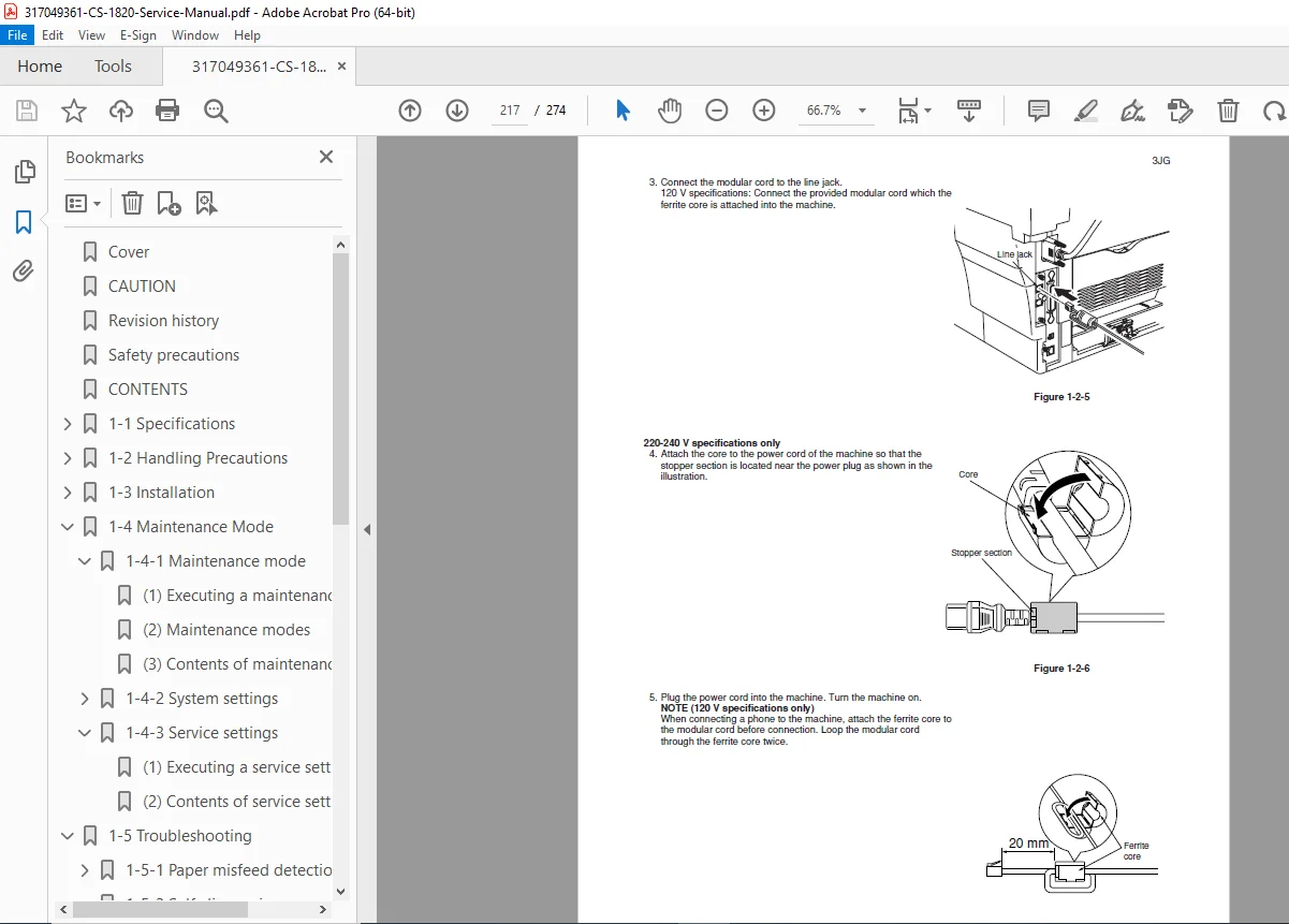
1-3-5 Fax System Installation (Optional):
- Fax board installation
- Cable connections
- Configuration procedures
CHAPTER 1-4: MAINTENANCE MODE (Pages 1-4-1 to 1-4-22)
1-4-1 Maintenance Mode (17 pages):
- Executing maintenance items – Access procedures
- Maintenance mode menu structure
- Complete maintenance mode contents:
- Drum refresh procedures
- Charge adjustment
- Transfer adjustment
- Exposure adjustment
- Developer refresh
- Various test patterns
- Counter readings
- Error history
- Component life monitoring
1-4-2 System Settings:
- Executing system setting procedures
- Complete system settings menu
- Configuration options
- Default value restoration
1-4-3 Service Settings:
- Service mode access procedures
- Service setting item contents
- Advanced configuration options
- Calibration procedures
CHAPTER 1-5: TROUBLESHOOTING (Pages 1-5-1 to 1-5-25)
1-5-1 Paper Misfeed Detection:
- Paper misfeed indication codes
- Detection conditions for each sensor
- Paper misfeed locations with diagrams
- Clearance procedures for each location
1-5-2 Self-Diagnosis:
- Self-diagnostic function overview
- Complete self-diagnostic code reference:
- Error code meanings
- Probable causes
- Corrective actions
- Component testing procedures
1-5-3 Image Formation Problems (7 pages): Comprehensive troubleshooting for:
- No image appears (entirely white)
- No image appears (entirely black)
- Image is too light
- Background is visible
- White line appears longitudinally
- Black line appears longitudinally
- Black line appears laterally
- One side darker than other
- Black dots on image
- Image is blurred
- Leading edge misalignment
- Paper creases
- Offset occurs
- Image partly missing
- Poor fixing
- Image center misalignment
Each problem includes:
- Symptom description
- Probable causes
- Inspection procedures
- Corrective actions
1-5-4 Electrical Problems: Systematic troubleshooting for:
- Machine does not operate (power on)
- Main motor does not operate
- Scanner motor does not operate
- Cooling fan does not operate
- Feed clutch does not operate
- MP feed clutch does not operate
- Registration clutch does not operate
- Eraser lamp does not turn on
- Exposure lamp does not turn on
- Exposure lamp does not turn off
- Heater lamp does not turn on
- Heater lamp does not turn off
- Main charging not performed
- Transfer charging not performed
- Paper jam indicated at power-on
- Cover closed message error
- Other electrical issues
1-5-5 Mechanical Problems:
- No primary paper feed
- No secondary paper feed
- Skewed paper feed
- Scanner does not travel
- Multiple sheet feeding
- Paper jams
- Abnormal noise
CHAPTER 1-6: ASSEMBLY AND DISASSEMBLY (Pages 1-6-1 to 1-6-30+)
1-6-1 Assembly/Disassembly Precautions:
- Safety guidelines
- Tool requirements
- Part handling procedures
1-6-2 Process Unit Removal:
- Photoconductor drum unit removal
- Developer unit access
1-6-3 Principal Outer Covers:
- Front top cover/face-down output tray removal
- Right cover removal procedures
- Left cover removal procedures
1-6-4 Feed Roller Removal:
- Cassette feed roller access
- Roller replacement procedures
1-6-5 MP Feed Roller Removal:
- Multi-purpose tray roller access
- Installation procedures
1-6-6 Transfer Roller Removal:
- Transfer assembly access
- Roller replacement
1-6-7 Primary Circuit PWB Removal:
- Engine PWB removal procedures
- Main PWB removal and installation
- Power supply PWB and high voltage PWB access
- Bias PWB removal
1-6-8 Main Motor and Drive Unit:
- Motor removal procedures
- Drive gear assembly access
- Clutch assemblies
1-6-9 Fuser Unit Removal and Disassembly: Complete fuser unit service including:
- Separation claws removal
- Heater lamp replacement
- Heat roller removal and installation
- Thermistor removal
- Thermal cutout replacement
- Press roller removal
1-6-10 Scanner Unit Removal:
- Optical assembly access
- Scanner motor removal
- Mirror and lens access
Additional Disassembly Sections:
- Registration section
- Paper exit section
- Sensor locations and removal
- Switch assemblies
- Drive clutches
- All major subassemblies
CHAPTER 2: ELECTRICAL SYSTEM
Complete electrical documentation:
- Wiring diagrams for all circuits
- Schematic diagrams of control boards
- PWB (Printed Wiring Board) layouts:
- Engine PWB
- Main PWB
- Power supply PWB
- High voltage PWB
- Bias PWB
- Optional board layouts
- Component location diagrams
- Connector pinout tables
- Voltage measurements at test points
- Signal flow diagrams
- Fax system wiring (optional)
- Network interface connections
CHAPTER 3: MECHANICAL SYSTEM
Detailed mechanical documentation:
- Drive system diagrams
- Timing charts for all operations
- Gear train layouts
- Clutch operation sequences
- Paper path diagrams with sensor locations
- Scanner mechanism operation
- Fuser mechanism detailed views
- Developer unit internal structure
- Registration system mechanics
- Separation mechanisms
CHAPTER 4: ADJUSTMENT PROCEDURES
Complete adjustment specifications:
- Image density adjustments
- Transfer bias adjustments
- Exposure lamp adjustments
- Registration adjustments
- Fuser temperature calibration
- Scanner home position setting
- Drum refresh procedures
- Developer refresh procedures
- All critical alignments
CHAPTER 5: PARTS CATALOG
Comprehensive illustrated parts lists:
- Exploded view diagrams for all assemblies
- Part numbers for all serviceable components
- Parts descriptions
- Quantity required for each part
- Replacement intervals for consumables
- Assembly-level breakdowns
Major sections include:
- Main body assemblies
- Process unit components
- Fuser unit parts
- Scanner unit parts
- Feed system components
- Exit system components
- Electrical components
- Optional unit parts (document processor, fax system)
- Consumables and supplies
⚙️ Technical Systems Documented
Indirect Electrostatic Copying System:
- Photoconductor drum charging
- Laser exposure (indirect system)
- Developer application
- Transfer process
- Fixing process
- Drum cleaning
- Complete theory of operation
Paper Handling System:
- Dual feed sources (cassette + MP tray)
- Registration system
- Transport mechanism
- Fixing unit
- Exit system with face-down tray
- Multi-sheet capacity management
Control System:
- Microprocessor control architecture
- Sensor monitoring
- Motor control
- Clutch timing
- Temperature control
- Self-diagnostic functions
Optional Systems:
- Document processor automation
- Network printing capabilities
- Fax transmission/reception
- Memory expansion
🎯 Who Should Use This Manual?
- Copier service technicians maintaining Copystar equipment
- Office equipment technicians servicing digital copiers
- Authorized service centers for Copystar/Kyocera products
- Corporate IT departments with in-house copier maintenance
- Technical training programs teaching copier repair
- Facilities management teams maintaining office equipment
- Independent service companies authorized for Copystar service
- Biomedical/educational institutions maintaining their copier fleets
✅ Why This Manual is Essential
✔ Official Copystar documentation – Authentic manufacturer service guide
✔ Complete system coverage – All components and assemblies documented
✔ Detailed troubleshooting – Systematic diagnostic procedures for all issues
✔ Full electrical schematics – Complete wiring and circuit diagrams
✔ Mechanical system diagrams – Drive trains, timing charts, mechanisms
✔ Assembly/disassembly procedures – Step-by-step with illustrations
✔ Parts catalog included – Exploded views with part numbers
✔ Maintenance mode access – Service functions and adjustments
✔ Self-diagnostic codes – Complete error code reference
✔ Fax system documentation – Optional fax board coverage
✔ Safety procedures – Proper handling and precautions
✔ Installation guidance – Complete setup and option installation
📥 Instant Digital Download
Receive your PDF manual immediately after purchase. Compatible with all devices – desktop, laptop, tablet, smartphone. Print sections for field service use or keep digital for quick reference during service calls.