Kyocera KM-C2630 / KM-C2630D Service Repair Manual + Parts List – PDF Download
Original price was: $27.95.$19.95Current price is: $19.95.
Kyocera KM-C2630 / KM-C2630D Service Repair Manual + Parts List
Description
Kyocera KM-C2630 / KM-C2630D Service Repair Manual + Parts List
FILE DETAILS:
FILE TYPE:PDF
DOWNLOADABLE:YES
MANUAL LANGUAGE:ENGLISH
PAGES:1200+
SAMPLE PAGE FROM THE MANUAL:
- In duplex printing, paper ejected from the fuser unit for which printing onto the first side (front side) is complete is guided toward the lower part of the fuser unit along the duplex guide of which the direction has been changed, and fed to the separation B roller in the ejection feedshift assembly.
- The paper that reaches the separation B roller is conveyed with rotation of the separation B roller, passes between the duplex A guide and the duplex A guide plate in the duplex conveying A assembly, and then is fed toward the duplex roller in the duplex conveying B assembly.
- After the paper turns on the duplex guide sensor in the duplex conveying B assembly, the leading edge of the paper that reaches the duplex roller is ejected onto the left guide of the intermediate tray in the duplexer with rotation of the duplex roller, passes under the duplex forwarding pulley that has been raised, and is fed toward the right guide of the intermediate tray.
- After ejection progresses and specified time elapses since the trailing edge of the paper turns off the paper guide sensor, the duplex tapping solenoid is activated, the trailing edge tapping guide lowers, and the trailing edge of the paper is tapped down onto the left guide of the intermediate tray.
- At the next timing, the duplex side registration motor is activated to move the duplex side registration guide according to the paper size and positions the paper located on the left guide of the intermediate tray to the center of the paper path. After positioning, the duplex forwarding solenoid is activated and lowers the duplex forwarding pulley to ground the paper located on the left guide of the intermediate tray.
- The paper is conveyed with rotation of the duplex forwarding pulley, the trailing edge of the paper becomes the leading edge, and the paper is fed toward the switchback pulley. The paper reaches the switchback pulley after turning on the duplex conveying sensor, is conveyed with rotation of the switchback pulley, is guided toward the lower part of the duplexer along the switchback feedshift guide, turns on the duplex registration sensor, and then is fed toward the duplex registration roller.
- The paper that reaches the duplex registration roller is conveyed with rotation of the duplex registration roller and is fed to the lower duplex conveying roller. The paper that reaches the lower duplex conveying roller is conveyed with rotation of the lower duplex conveying roller and is fed toward the lower duplex conveying B roller.
- The paper that reaches the lower duplex conveying B roller is conveyed with rotation of the lower duplex conveying B roller, goes out of the duplexer, and is fed toward the ejection guide assembly. The paper is guided into the machine along the upper duplex guide and the lower duplex paper feed guide that constitute the ejection guide assembly, and the leading edge of the paper turns on the registration sensor.
- At this time, primary paper feed of the second side (reverse side) of paper (refeed) is complete.In duplex printing, paper ejected from the fuser unit for which printing onto the first side (front side) is complete is guided toward the lower part of the fuser unit along the duplex guide of which the direction has been changed, and fed to the separation B roller in the ejection feedshift assembly.
- The paper that reaches the separation B roller is conveyed with rotation of the separation B roller, passes between the duplex A guide and the duplex A guide plate in the duplex conveying A assembly, and then is fed toward the duplex roller in the duplex conveying B assembly.
- After the paper turns on the duplex guide sensor in the duplex conveying B assembly, the leading edge of the paper that reaches the duplex roller is ejected onto the left guide of the intermediate tray in the duplexer with rotation of the duplex roller, passes under the duplex forwarding pulley that has been raised, and is fed toward the right guide of the intermediate tray.
- After ejection progresses and specified time elapses since the trailing edge of the paper turns off the paper guide sensor, the duplex tapping solenoid is activated, the trailing edge tapping guide lowers, and the trailing edge of the paper is tapped down onto the left guide of the intermediate tray.
- At the next timing, the duplex side registration motor is activated to move the duplex side registration guide according to the paper size and positions the paper located on the left guide of the intermediate tray to the center of the paper path. After positioning, the duplex forwarding solenoid is activated and lowers the duplex forwarding pulley to ground the paper located on the left guide of the intermediate tray.
- The paper is conveyed with rotation of the duplex forwarding pulley, the trailing edge of the paper becomes the leading edge, and the paper is fed toward the switchback pulley. The paper reaches the switchback pulley after turning on the duplex conveying sensor, is conveyed with rotation of the switchback pulley, is guided toward the lower part of the duplexer along the switchback feedshift guide, turns on the duplex registration sensor, and then is fed toward the duplex registration roller.
- The paper that reaches the duplex registration roller is conveyed with rotation of the duplex registration roller and is fed to the lower duplex conveying roller. The paper that reaches the lower duplex conveying roller is conveyed with rotation of the lower duplex conveying roller and is fed toward the lower duplex conveying B roller.
- The paper that reaches the lower duplex conveying B roller is conveyed with rotation of the lower duplex conveying B roller, goes out of the duplexer, and is fed toward the ejection guide assembly.
- The paper is guided into the machine along the upper duplex guide and the lower duplex paper feed guide that constitute the ejection guide assembly, and the leading edge of the paper turns on the registration sensor. At this time, primary paper feed of the second side (reverse side) of paper (refeed) is complete.
TABLE OF CONTENTS:
1-1 Specifications
1-1-1 Specifications 1-1-1
1-1-2 Parts names 1-1-3
(1) Copier 1-1-3
(2) Operation panel 1-1-4
1-1-3 Cross section view 1-1-5
(1) Simplex copier 1-1-5
(2) Duplex copier 1-1-6
1-2 Handling Precautions
1-2-1 Drum unit (process unit) 1-2-1
1-2-2 Drum unit (process unit) and toner container 1-2-1
1-2-3 Installation environment 1-2-1
1-3 Installation
1-3-1 Unpacking and installation 1-3-1
(1) Installation procedure 1-3-1
1-3-2 Setting initial copy modes 1-3-17
1-3-3 Installing the key counter (option) 1-3-18
1-3-4 Installing the dehumidifier heater (optional) 1-3-21
1-3-5 Installing the 500-sheet paper feeder (option) 1-3-23
1-3-6 Installing the 1500-sheet paper feeder (option) 1-3-28
1-3-7 Installing the 3000-sheet paper feeder (option) 1-3-31
1-3-8 Installing the document finisher (option) 1-3-35
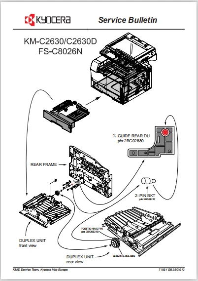
1-3-9 Installing the duplex unit (optional for simplex copiers) 1-3-52
1-3-10 Installing the left tray (option) 1-3-64
1-3-11 Installing the memory copy board/network scanner kit (option) 1-3-65
1-3-12 Installing the printing system (option) 1-3-70
1-3-13 Installing the fax system (option) 1-3-73
1-3-14 Installing the sheet-through Document Processor (option) 1-3-83-1
1-4 Maintenance Mode
1-4-1 Copier management 1-4-1
(1) Using the copier management mode 1-4-1
(2) Setting department management items 1-4-2
(3) Copy default 1-4-3
(4) Machine default 1-4-6
(5) Bypass setting 1-4-7
(6) Original size registration .1-4-7
(7) User adjustment 1-4-8
(8) Checking the total counter and printing out the counter report 1-4-8
(9) Status report print out 1-4-8
(10) Language selection function 1-4-8
1-4-2 Maintenance mode 1-4-9
(1) Executing a maintenance item 1-4-9
(2) Maintenance mode item list .1-4-10
(3) Contents of the maintenance mode items 1-4-15
1-5 Troubleshooting
1-5-1 Paper misfeed detection 1-5-1
(1) Paper misfeed indication 1-5-1
(2) Paper misfeed detection conditions 1-5-2
(3) Paper misfeeds 1-5-9
1-5-2 Self-diagnosis 1-5-24
(1) Self-diagnostic function 1-5-24
(2) Self diagnostic codes 1-5-26
1-5-3 Image formation problems 1-5-51
(1) No image appears (entirely white) .1-5-52
(2) No image appears (entirely black) .1-5-53
2BG
(3) Dirty on the top edge 1-5-53
(4) Image is too light. 1-5-54
(5) The background is colored. 1-5-55
(6) A white line appears longitudinally. 1-5-56
(7) A black line appears longitudinally. 1-5-57
(8) A black line appears laterally 1-5-57
(9) Black dots appear on the image .1-5-58
(10) The leading edge of the image is consistently misaligned with the original. 1-5-58
(11) Paper creases. 1-5-59
(12) Offset occurs. 1-5-59
(13) Image is partly missing .1-5-59
(14) Fixing is poor. 1-5-60
(15) Colors are printed offset to each other. 1-5-60
1-5-4 Electric problems 1-5-61
(1) The machine does not operate when the power switch is turned on. 1-5-61
(2) The developing K/fuser motor does not operate (C2101). 1-5-61
(3) The developing MCY motor does not operate (C2102) 1-5-61
(4) The drum motor K does not operate (C2201). 1-5-62
(5) The drum motor C does not operate (C2202). 1-5-62
(6) The drum motor M does not operate (C2203) .1-5-62
(7) The drum motor Y does not operate (C2204). 1-5-62
(8) The paper feed motor does not operate (C2500) 1-5-62
(9) The toner motor K does not operate. 1-5-63
(10) The toner motor C does not operate. 1-5-63
(11) The toner motor M does not operate .1-5-63
(12) The toner motor Y does not operate. 1-5-63
(13) The transfer motor does not operate .1-5-63
(14) The transfer roller lift motor does not operate. 1-5-64
(15) The cassette lift motor does not operate. 1-5-64
(16) The duplex side registration motor does not operate. 1-5-64
(17) The main charger fan motor does not operate. 1-5-64
(18) The main cooling fan motor does not operate .1-5-64
(19) The power supply PWB cooling fan motor does not operate. 1-5-64
(20) The scanner motor does not operate. 1-5-64
(21) The electric component unit fan motor does not operate. 1-5-65
(22) The conveying H clutch does not operate. 1-5-65
(23) The conveying L clutch does not operate .1-5-65
(24) The primary paper feed H clutch does not operate. 1-5-65
(25) The primary paper feed L clutch does not operate 1-5-65
(26) The paper feeder feed H clutch does not operate .1-5-66
(27) The paper feeder feed L clutch does not operate. 1-5-66
(28) The bypass feed clutch does not operate. 1-5-66
(29) The registration clutch does not operate. 1-5-66
(30) The duplex feed clutch does not operate. 1-5-66
(31) The fuser clutch does not operate .1-5-66
(32) The paper feeder upper feed H clutch* does not operate. 1-5-67
(33) The paper feeder middle feed H clutch* does not operate 1-5-67
(34) The paper feeder lower feed H clutch* does not operate 1-5-67
(35) The paper feeder upper feed L clutch* does not operate 1-5-67
(36) The paper feeder conveying H clutch* does not operate. 1-5-67
(37) The paper feeder conveying L clutch* does not operate .1-5-67
(38) The right deck feed clutch* does not operate 1-5-68
(39) The left deck feed clutch* does not operate. 1-5-68
(40) The left deck conveying clutch* does not operate .1-5-68
(41) The lift plate up/down solenoid does not operate 1-5-68
(42) The face-up exit solenoid does not operate. 1-5-68
(43) The duplex exit solenoid does not operate .1-5-69
(44) The duplex tapping solenoid does not operate. 1-5-69
(45) The duplex forwarding solenoid does not operate. 1-5-69
(46) The eraser lamp K does not turn on 1-5-69
(47) The eraser lamp C does not turn on 1-5-69
(48) The eraser lamp M does not turn on. 1-5-69
(49) The eraser lamp Y does not turn on 1-5-70
2BG
(50) The exposure lamp does not turn on .1-5-70
(51) The exposure lamp does not turn off .1-5-70
(52) The fuser heater lamp does not turn on. 1-5-70
(53) The fuser heater lamp does not turn off. 1-5-70
(54) No main charging. 1-5-70
(55) No developing bias is output. 1-5-71
(56) No transfer bias is output. 1-5-71
(57) The original size is not detected .1-5-71
(58) The original size is not detected correctly. 1-5-71
(59) The touch panel keys do not work .1-5-71
(60) The message requesting paper to be loaded is shown
when paper is present in the copier cassette. 1-5-71
(61) The message requesting paper to be loaded is shown
when paper is present on the bypass tray 1-5-72
(62) The size of paper in the copier cassette is not displayed correctly. 1-5-72
(63) The size of paper on the bypass tray is not displayed correctly 1-5-72
(64) A paper jam in the paper feed, paper conveying or fuser section is indicated
when the power switch is turned on. 1-5-72
(65) The message requesting cover to be closed is displayed when the front cover is closed. 1-5-73
(66) Others 1-5-73
1-5-5 Mechanical problems 1-5-74
(1) No primary paper feed 1-5-74
(2) No secondary paper feed. 1-5-74
(3) Skewed paper feed. 1-5-74
(4) The scanner does not travel 1-5-74
(5) Multiple sheets of paper are fed at one time. 1-5-74
(6) Paper jams. 1-5-74
(7) Toner drops on the paper conveying path 1-5-74
(8) Abnormal noise is heard .1-5-75
1-6 Assembly and Disassembly
1-6-1 Precautions for assembly and disassembly 1-6-1
(1) Precautions 1-6-1
(2) Running a maintenance item .1-6-2
1-6-2 Outer covers 1-6-3
(1) Detaching and refitting the top cover .1-6-3
(2) Detaching and refitting the rear cover 1-6-6
(3) Detaching and refitting the eject unit 1-6-7
1-6-3 Primary paper feed unit .1-6-8
(1) Detaching and refitting the primary paper feed unit 1-6-8
(2) Detaching and refitting the forwarding roller and paper feed roller 1-6-10
(3) Detaching and refitting the lower paper feed pulley 1-6-11
(4) Adjustment after roller and clutch replacement 1-6-12
(4-1) Adjusting the leading edge registration of image printing 1-6-12
(4-2) Adjusting the center line of image printing 1-6-13
(4-3) Adjusting the margins for printing .1-6-14
(4-4) Adjusting the amount of slack in the paper 1-6-15
(4-5) Adjusting the leading edge registration for duplex switchback copying 1-6-16
1-6-4 Bypass feed unit 1-6-17
(1) Detaching and refitting the bypass feed roller and bypass retard roller 1-6-17
1-6-5 Optical section 1-6-18
(1) Detaching and refitting the exposure lamp .1-6-18
(2) Detaching and refitting the scanner wires 1-6-20
(2-1) Detaching the scanner wires 1-6-20
(2-2) Fitting the scanner wires 1-6-25
(3) Detaching and refitting the ISU (reference) 1-6-30
(4) Detaching and refitting the original size detection switch 1-6-31
(5) Adjusting magnification of the scanner in the main scanning direction .1-6-32
(6) Adjusting magnification of the scanner in the auxiliary scanning direction .1-6-33
(7) Adjusting the scanner leading edge registration 1-6-34
(8) Adjusting the scanner center line 1-6-35
(9) Adjusting the margins for scanning an original on the contact glass 1-6-36
2BG
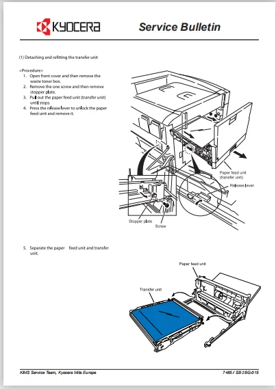
1-6-6 Transfer unit 1-6-37
(1) Detaching and refitting the transfer unit 1-6-37
1-6-7 Process section 1-6-38
(1) Detaching and refitting the process unit 1-6-38
(2) Detaching and refitting the drum unit and developer 1-6-40
1-6-8 Fuser unit 1-6-42
(1) Detaching and refitting the fuser unit .1-6-42
(2) Detaching and refitting the upper and lower fuser thermistors,
upper and lower fuser thermostats, upper and lower fuser heater lamps and
upper and lower fuser rollers 1-6-43
1-6-9 PWBs 1-6-50
(1) Detaching and refitting the scanner main PWB and scanner sub PWB 1-6-50
(2) Detaching and refitting the scanner power supply PWB 1-6-51
(3) Detaching and refitting the engine controller PWB 1-6-52
(4) Detaching and refitting the power supply PWB .1-6-53
(5) Detaching and refitting the main high voltage PWB .1-6-55
(6) Detaching and refitting the bias high voltage PWB 1-6-56
(7) Detaching and refitting the LPH drive PWB 1-6-57
(8) Detaching and refitting the front relay PWB 1-6-58
1-6-10 Others 1-6-59
(1) Detaching and refitting the developing MCY motor 1-6-59
(2) Detaching and refitting the drum motors K, M, C and Y 1-6-60
(3) Detaching and refitting the toner motors K, M, C and Y 1-6-61
(4) Detaching and refitting the cassette lift motor 1-6-62
(5) Detaching and refitting the paper feed motor 1-6-63
(6) Detaching and refitting the paper feed drive unit .1-6-64
(7) Detaching and refitting the developing K/fuser motor 1-6-65
(8) Detaching and refitting the ozone filter 1-6-66
(9) Detaching and refitting the LED print head 1-6-67
(10) Adjusting the focus of the LED print head 1-6-70
1-7 Requirements on PWB Replacement
1-7-1 Upgrading the firmware .1-7-1
1-7-2 Adjustment-free variable resistors (VR) 1-7-2
1-7-3 Remarks on engine controller PWB replacement 1-7-2
1-7-4 Remarks on scanner main PWB replacement 1-7-2
1-7-5 Upgrading the printer board firmware 1-7-3
2-1 Mechanical construction
2-1-1 Paper feed section 2-1-1
(1) Paper cassette, primary paper feed unit and paper feeder feed section .2-1-1
(2) Bypass unit and paper feed unit .2-1-3
2-1-2 Process section 2-1-5
(1) Developers and drum unit 2-1-5
(2) Main charger unit .2-1-7
(3) LED print head 2-1-8
2-1-3 Transfer section 2-1-10
(1) Transfer unit 2-1-10
2-1-4 Fuser section 2-1-14
(1) Fuser unit 2-1-14
2-1-5 Exit section 2-1-16
(1) Eject unit and face-down exit section 2-1-16
2-2 Electrical Parts Layout
2-2-1 Electrical parts layout 2-2-1
(1) Main front, upper, left, inner and paper cassette .2-2-1
(2) Main rear 2-2-3
(3) Main right and primary paper feed unit 2-2-5
(4) Paper feed unit, bypass unit and transfer unit 2-2-6
(5) Process unit and fuser unit 2-2-7
(6) Scanner unit, electrical component unit and operation unit .2-2-8
2BG
2-3 Operation of the PWBs
2-3-1 Power supply PWB 2-3-1
2-3-2 Scanner power supply PWB 2-3-5
2-3-3 Engine controller PWB 2-3-7
2-3-4 Scanner main PWB, scanner sub PWB and scanner MIP PWB 2-3-20
(1) Scanner main PWB and scanner sub PWB 2-3-25
(2) Scanner MIP PWB 2-3-32
2-3-5 LPH drive PWB 2-3-37
2-3-6 CCD PWB 2-3-44
2-3-7 Operation unit PWB 2-3-46
2-4 Appendixes
Timing chart No.1 .2-4-1
Timing chart No.2 .2-4-2
Timing chart No.3 .2-4-3
Timing chart No.4 .2-4-4
Timing chart No.5 .2-4-5
Timing chart No.6 .2-4-6
Timing chart No.7 2-4-7
Chart of image adjustment procedures .2-4-8
Image quality .2-4-10
Maintenance parts list 2-4-11
Maintenance kits 2-4-11
Periodic maintenance procedures 2-4-12
General wiring diagram .2-4-15
SCREENSHOT OF THE MANUAL:
KYOCERA KM-C2630 / KM-C2630D SERVICE REPAIR MANUAL + PARTS LIST – PDF DOWNLOAD:
PLEASE NOTE:
⦁ This is the SAME exact manual used by your dealers to fix your vehicle.
⦁ The same can be yours in the next 2-3 mins as you will be directed to the download page immediately after paying for the manual.
⦁ Any queries / doubts regarding your purchase, please feel free to contact [email protected]
Mark Apollo –
I’ve already responded to an order that included this item. Transaction satisfactory.
Samir Braden –
SO FAR SO GOOD, SURVEY SHOULD BE TAKEN AFTER DOWNLOAD
Bellamy Cain –
Can not open file