
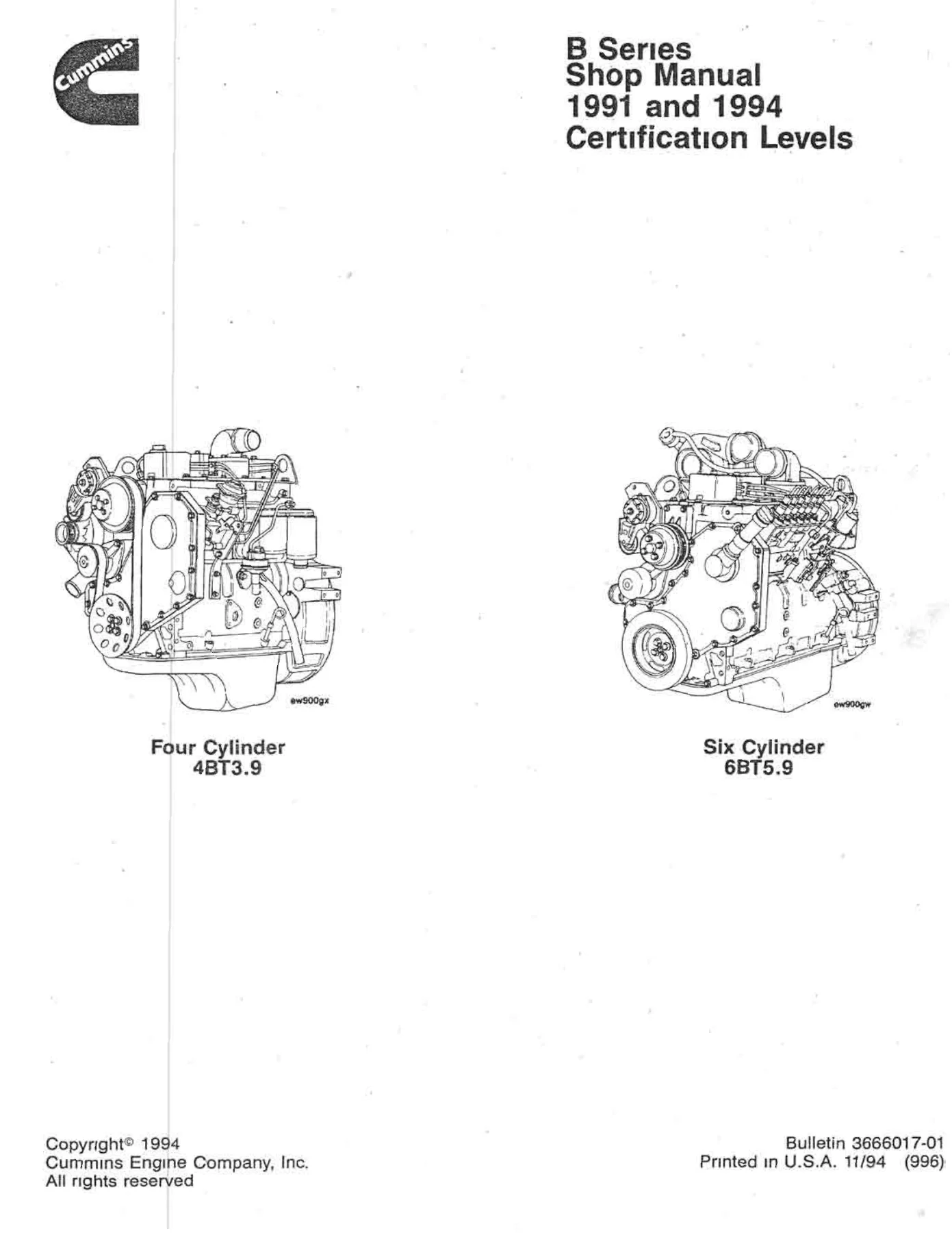
Cummins B Series Shop Manual 1991 and 1994 Certification Levels – 4BT3.9 6BT5.9 PDF
Original price was: $59.95.$39.95Current price is: $39.95.
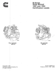
Complete Cummins B Series shop manual for 1991 and 1994 certification levels, covering 4BT3.9, 6BT5.9 and related B Series engine rebuild, disassembly, assembly, specifications and service procedures.
Description
Cummins B Series Shop Manual – 1991 and 1994 Certification Levels
This Cummins B Series Shop Manual contains complete rebuild specifications and information for the B Series engines and associated components manufactured by Cummins Engine Company, Inc. The coverage note in the manual applies it to 1991 and newer engines starting with ESN 44566920; for prior built engines it points to the B Series Shop Manual, Bulletin No. 3810206-02. The 1991 and 1994 certification levels are part of the document identity, so it is a practical reference when working on engines from those certification periods.
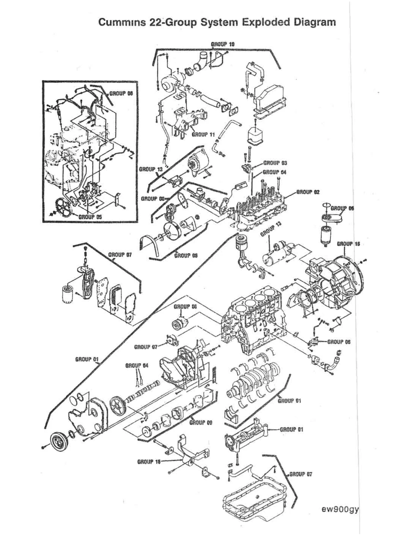
The content is arranged in the Cummins 22-group system. That structure keeps engine identification, disassembly and assembly, cylinder block, cylinder head, fuel system, lubrication, cooling, drive units, air intake, exhaust, electrical equipment, engine testing, mounting adaptations and specifications in predictable locations. For anyone working on a 4BT3.9, 6BT5.9, 4BTA3.9, 6BTA5.9 or the automotive B3.9 and B5.9 variants shown in the manual, this grouping matters because it mirrors how Cummins service literature is organized.
File Details
- Manual type: Shop Manual
- Brand/model: Cummins B Series
- Language: English
- Page count: 461 pages
- File format: PDF
Chapters Covered
- Introduction
- Engine Identification
- Engine Disassembly and Assembly – Group 00
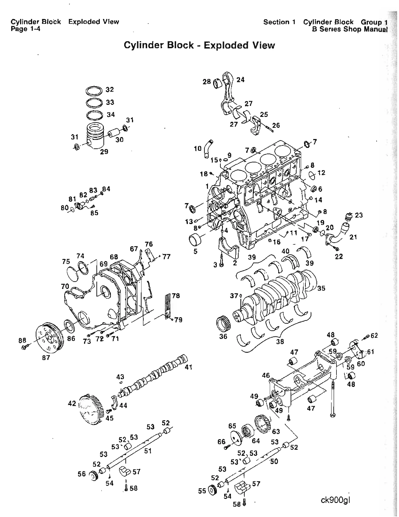
- Cylinder Block – Group 01
- Cylinder Head – Group 02
- Rocker Levers – Group 03
- Cam Followers – Group 04
- Fuel System – Group 05
- Injectors and Fuel Lines – Group 06
- Lubricating Oil System – Group 07
- Cooling System – Group 08
- Drive Units – Group 09
- Air Intake System – Group 10
- Exhaust System – Group 11
- Air Equipment – Group 12
- Electrical Equipment – Group 13
- Engine Testing – Group 14
- Mounting Adaptations – Group 16
- Specifications – Group 18
- Service Literature
- Component Manufacturers: Names and Addresses
- Index
Introduction and Engine Identification
The opening sections explain how to use the manual, how the 22-group system is organized, and how the symbols and metric information are presented. Both metric and U.S. customary values are used, with the metric value listed first and the U.S. customary value in brackets. Engine dataplate information, industrial engine nomenclature, automotive engine nomenclature and injection pump dataplate locations are covered, including Bosch, Lucas CAV, Stanadyne and in-line pump examples. This is the section to read before ordering parts or confirming which B Series variant is in front of you.
Engine Disassembly and Assembly – Group 00
Group 00 is the teardown and rebuild backbone. It covers engine disassembly, cleaning, mounting on a rollover stand, accessory removal, cylinder head removal, front cover removal, water pump removal, flywheel and flywheel housing removal, injection pump removal for rotary and in-line pumps, gear lash checks, timing pin procedures, camshaft removal, piston and rod assembly removal, crankshaft removal, cylinder block preparation, and the matching installation procedures. Service tools such as the fuel pump drive gear puller, piston ring compressor, engine barring tool, injector bore brush and engine rebuild stand adapter are shown with their part numbers where the manual lists them.
Cylinder Block – Group 01
The cylinder block group covers disassembly, cleaning, inspection, de-glazing, expansion plug and pipe plug installation, camshaft bushing installation, crankshaft cleaning and inspection, crankshaft gear replacement, piston and connecting rod disassembly, piston inspection, piston pin inspection, connecting rod inspection, rod bearing clearance checking, piston ring gap checking and piston ring installation. It also covers balancer disassembly and assembly for the four-cylinder engine, plus cylinder block storage and data plate replacement.
Cylinder Head – Group 02
The cylinder head section covers precheck before disassembly, disassembly, cleaning, valve inspection, valve guide inspection, valve seat inspection, valve spring inspection, combustion face inspection, crack reuse guidelines, cup plug replacement, valve seat grinding, grinding depth calculation, valve depth measurement, valve grinding and cylinder head assembly. This is the area where valve and seat condition, guide wear and head flatness are evaluated before rebuild decisions are made.
Rocker Levers and Cam Followers – Groups 03 and 04
The rocker lever and cam follower groups support the valvetrain work that follows cylinder head service. They cover the components that transfer camshaft motion to the valves, including inspection and rebuild information for the rocker lever assemblies and cam followers. These sections are used together with the cylinder head group and the valve clearance adjustment procedure in Group 00.
Fuel System and Injectors and Fuel Lines – Groups 05 and 06
The fuel system group covers the injection pump and related fuel system components, with separate removal and installation guidance for rotary and in-line injection pumps. The injectors and fuel lines group covers injector nozzle removal and installation, high-pressure fuel line removal and installation, fuel drain manifold service, low-pressure fuel lines, fuel filter head service and the KSB remote-mounted assembly. Injection pump dataplate information and drive gear backlash checks are included where the manual presents them.
Lubricating Oil, Cooling and Drive Units – Groups 07, 08 and 09
The lubricating oil system group covers the oil pan, suction tube, oil cooler, oil filter, lube pump and related sealing surfaces. The cooling system group covers the water pump, thermostat, water inlet connection and cooling system inspection points. The drive units group covers gear housing, gear train components, backlash measurement and drive unit service. These groups are closely tied to the disassembly and assembly sequence in Group 00 because seals, gaskets, gear lash and cleaning surfaces must be handled in the correct order.
Air Intake, Exhaust, Air Equipment and Electrical Equipment – Groups 10 through 13
These groups cover the air intake system, exhaust manifold and turbocharger-related hardware, air equipment and electrical equipment. The manual includes turbocharger removal and installation, exhaust manifold removal and installation, manifold cover and aftercooler service, alternator removal and installation, starter removal and installation, and the associated mounting hardware and torque values. Electrical components, wiring and certain fuel system parts are specifically called out in the cleaning instructions as items that should not be steam cleaned.
Engine Testing, Mounting Adaptations and Specifications – Groups 14, 16 and 18
Engine testing, mounting adaptations and specifications round out the technical coverage. The specifications group includes general engine data such as bore, stroke, displacement, compression ratios, firing order, valve settings, engine rotation, engine weight, lubrication system pressures and capacities, cooling system thermostat opening temperatures, pressure cap ratings, coolant capacity, intake and exhaust restrictions, and fuel system pressures and restrictions. The engine disassembly and assembly section also includes measured limits for gear backlash, camshaft end play and crankshaft end play.
Safety, Cleaning and Repair Practices
The general safety instructions cover protective equipment, battery disconnection, rotating parts, hot coolant, lifting procedures, refrigerant handling and the safe use of cleaning solvents. The general cleaning instructions distinguish between solvent and acid cleaning, steam cleaning, and glass or plastic bead cleaning, with specific warnings about aluminum piston skirts, ring grooves and injector components. General repair instructions identify safety-related components and stress the use of genuine Cummins or ReCon service parts where replacement is needed.
Put the B Series Shop Manual to Work
This Cummins B Series Shop Manual is built for the jobs that actually take time: identifying the correct engine variant, tearing down a 4BT3.9 or 6BT5.9 in the right sequence, checking gear backlash and end play, measuring bearing clearances, setting valve clearance, installing injectors and high-pressure lines correctly, and reassembling with the specified torque values and sealants. The group system lets you move from a symptom or a component to the relevant procedure without hunting through a generic repair guide. Because the manual includes measured limits and rebuild specifications, it supports decisions about reuse, replacement and machining rather than guesswork.
Whether the engine is in an industrial application or an automotive B3.9 or B5.9 installation, the same need applies: correct procedures and correct specifications. This PDF is delivered instantly after purchase, with no shipping and no waiting for a physical book. It can be viewed on a laptop, tablet or phone, and pages can be printed for the workshop when a paper copy is more practical. Keep the file on hand for planned rebuilds, routine service and the diagnosis work that comes before disassembly.
IMAGES PREVIEW
Reviews
There are no reviews yet.