
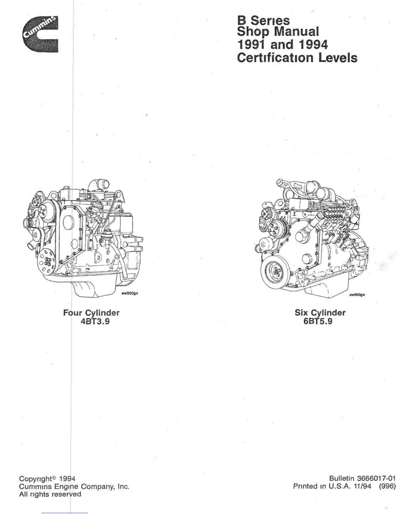
Cummins B Series 4BT3.9 6BT5.9 Shop Manual 1991 & 1994 Certification Levels PDF
Original price was: $19.95.$11.95Current price is: $11.95.
Cummins B Series shop manual covering four-cylinder 4BT3.9 and six-cylinder 6BT5.9 engines for 1991 and 1994 certification levels. This 461-page PDF includes engine identification and specifications, extensive Group 00 engine disassembly and assembly procedures, fuel injection pump installation and timing information, service tools, torque values, clearances, and the opening portion of the Cylinder Block Group 1 section.
Description
Cummins B Series 4BT3.9 6BT5.9 Shop Manual 1991 & 1994 Certification Levels PDF
This Cummins B Series 4BT3.9 6BT5.9 Shop Manual 1991 & 1994 Certification Levels PDF is a technical repair reference for four-cylinder 4BT3.9 and six-cylinder 6BT5.9 B Series engines. The manual identifies coverage for 1991 and newer engines starting with ESN 4456920 and provides detailed service information built around inspection, measurement, disassembly, installation, adjustment, and engine assembly work.
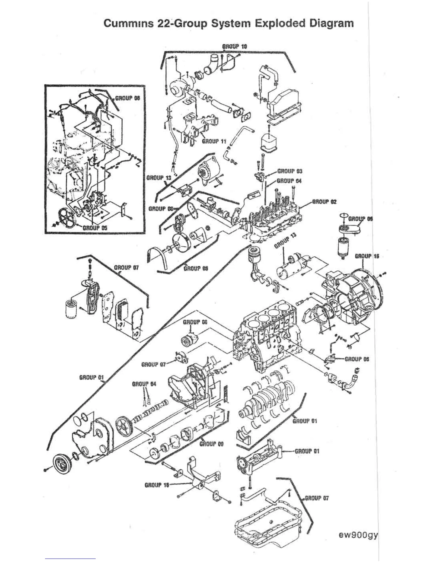
The pages combine step-by-step repair instructions with line illustrations, exploded views, service-tool references, tightening values, measurement limits, component identification, and engine specifications. A particularly large portion of this PDF is devoted to Group 00 engine disassembly and assembly, taking the technician through removal of major external components, internal engine teardown, crankshaft and piston work, gear-train setup, injection-pump installation and timing, cylinder-head installation, valve adjustment, and final reassembly.
File Details
- Manual type: B Series Shop Manual
- Brand: Cummins
- Models: 4BT3.9 four-cylinder and 6BT5.9 six-cylinder
- Certification levels: 1991 and 1994
- Engine coverage: 1991 and newer engines starting with ESN 4456920
- Language: English
- Pages: 461
- File format: PDF
- Bulletin: 3666017-01
- Printed: 11/94
Important Coverage Note
The front table of contents describes the broader B Series shop-manual structure, including cylinder head, rocker levers, cam followers, fuel system, injectors and fuel lines, lubricating oil, cooling, drive units, intake, exhaust, air equipment, electrical equipment, engine testing, mounting adaptations, and specifications. This 461-page PDF does not contain all of those later groups. The included file runs through the Introduction, Engine and Component Identification, the extensive Engine Disassembly and Assembly Group 00 section, and into the opening Cylinder Block Group 1 material. Buyers needing every group listed in the front contents should be aware of this limitation.
Engine Identification and Specifications
The identification section explains engine dataplate information, industrial and automotive engine nomenclature, and injection-pump dataplate locations. Illustrations show Robert Bosch VE, Lucas CAV DPA, Stanadyne DB4, and in-line injection-pump identification locations. Automotive engine diagrams identify service points and components from multiple views.
General engine specifications include a 102 mm bore and 120 mm stroke. Displacement is listed as 3.92 liters for the 4B and 5.88 liters for the 6B. The manual provides compression-ratio information for different naturally aspirated, turbocharged, and charge-air-cooled configurations, along with firing order, valve settings, engine rotation, wet engine weight, lubrication-system pressures and capacities, cooling-system data, intake and exhaust restrictions, fuel-system limits, and minimum recommended battery capacities.
Chapters Covered
- Introduction
- About the manual and how to use it
- General safety instructions
- General repair instructions
- General cleaning instructions
- Glossary of terms and instruction symbols
IMAGES PREVIEW

- Engine and Component Identification
- Engine dataplate and nomenclature
- Injection-pump dataplate locations
- General engine specifications
- Lubrication, cooling, intake, exhaust, fuel, and electrical data
- Automotive engine diagrams
- Engine Disassembly and Assembly – Group 00
- Engine disassembly checklist and service tools
- Starter, drive belt, fan pulley, vibration damper, belt tensioner, fan hub, and alternator removal
- Thermostat, turbocharger, exhaust manifold, filters, and fuel-system component removal
- High-pressure and low-pressure fuel lines
- Injector nozzles, rocker levers, push rods, and cylinder head removal
- Front cover, water pump, flywheel, and flywheel housing removal
- Rotary and in-line injection-pump removal
- Fuel transfer pump, tappet cover, oil cooler, oil pan, and suction tube removal
- Camshaft, valve tappets, lube pump, gear housing, and balancer removal
- Piston and connecting-rod removal
- Crankshaft removal and installation
- Piston and connecting-rod installation and piston protrusion measurement
- Gear housing and lube-pump installation
- Camshaft installation, end play, and gear backlash measurement
- Timing-pin and balancer installation
- Rear seal, suction tube, oil pan, oil cooler, and fuel-transfer-pump installation
- Injection-pump installation, locking, unlocking, and timing procedures
- Lucas CAV, Stanadyne DB4, Bosch VE, Bosch P7100, and Nippondenso pump-related procedures
- Flywheel housing, flywheel, water pump, front cover, and cylinder-head installation
- Cylinder-head tightening sequence
- Valve-clearance adjustment
- Injector-nozzle and valve-cover installation
- Fuel-line, exhaust-manifold, turbocharger, thermostat, alternator, drive-belt, oil-filter, and starter installation
- Cylinder Block – Group 1, included opening portion
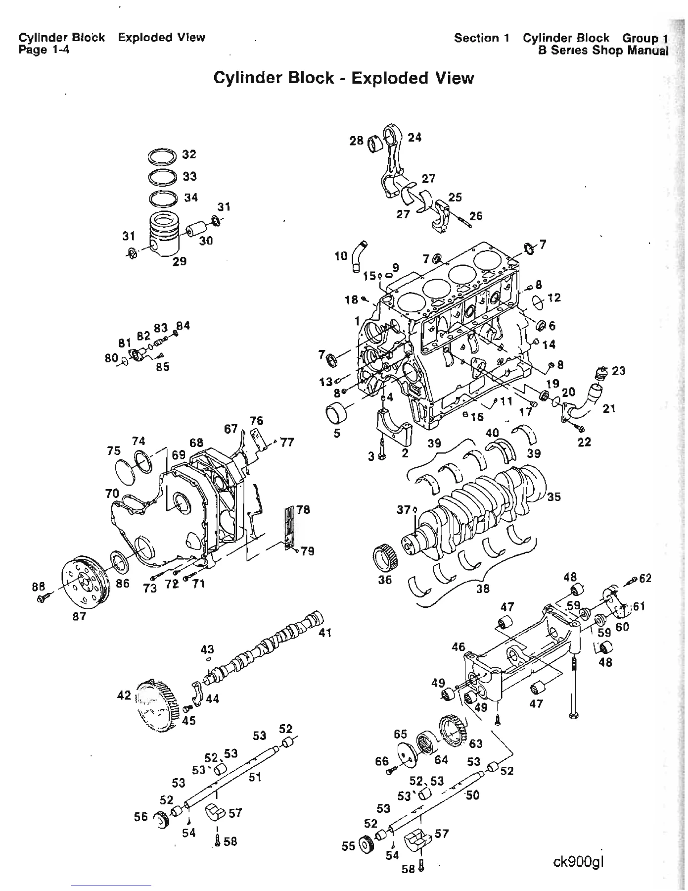
- Section contents and cylinder-block exploded view
- Cylinder-block general information
- Service tools
- Cylinder-block group inspection checklist
- Precheck before disassembly
- Initial cylinder-block disassembly and cleaning procedures
The Cummins 4BT3.9 and 6BT5.9 shop manual material is especially useful where correct assembly relationships and measurements matter. Procedures frequently specify tool sizes, tightening sequences, torque values, component positioning, lubrication steps, timing marks, backlash checks, end-play measurements, piston protrusion checks, and other details that are difficult to reproduce reliably from memory.
Engine Rebuild and Measurement Content
The Group 00 section provides a continuous engine teardown and assembly sequence rather than isolated component descriptions. It includes checking injection-pump drive gear, camshaft, lube-pump and balancer backlash, crankshaft end play, component weights, piston orientation, rod-cap matching, bearing installation, timing alignment, and valve adjustment. Numerous illustrations identify exactly where a measurement is taken or how a component is positioned during assembly.
Fuel-injection work receives substantial coverage. The manual distinguishes procedures for several pump types and explains removal, locked and unlocked installation, timing-pin use, drive-gear mounting, timing-mark alignment, pump unlocking, and associated fuel-line installation. These pages are useful when servicing an engine equipped with the pump configuration illustrated in the manual because the procedure varies according to pump design.
Cylinder Block Reference
The final portion begins the Cylinder Block Group 1 section with an exploded view and parts identification, followed by general information on the B Series block, crankshaft, camshaft, oil seals, pistons, and vibration damper. It also includes the group service-tool chart, an inspection checklist covering measurements such as head-deck flatness, bearing bores, camshaft bore, tappet bore, journal condition, piston and rod inspection, and bearing clearances, then starts the cylinder-block disassembly and cleaning sequence.
Use This Manual for Accurate B Series Engine Service
The Cummins B Series 4BT3.9 6BT5.9 Shop Manual 1991 & 1994 Certification Levels PDF supports substantial engine service work including teardown, component removal, crankshaft and piston installation, gear-train setup, injection-pump installation and timing, cylinder-head assembly, valve adjustment, and reinstallation of major engine accessories. Having the illustrated procedures, dimensional checks, torque values, tightening sequences, and specification data available while working helps reduce assembly errors and provides a consistent reference for critical engine measurements.
Delivery is as an instant PDF download after payment, with no physical shipping required. The file can be opened on compatible computers, tablets, and phones and pages can be printed when a paper reference is more convenient at the workbench.

Reviews
There are no reviews yet.