
DAF LF CF XF105 Bodybuilder Guidelines 2009-19 – Complete Truck Body Mounting, Chassis & Electrical Upfit Manual PDF
Original price was: $63.95.$39.95Current price is: $39.95.
The official DAF Trucks N.V. Bodybuilder Guidelines for LF, CF and XF105 chassis — 378 pages covering body attachment methods (BAM), sub-frame design, superstructure procedures, cab loading limits, PTO selection, compressed air take-offs and full electrical/CAN connector pin-outs. Instant PDF download.
Description
DAF LF, CF and XF105 Bodybuilder Guidelines – 2009-19 Edition
The DAF LF CF XF105 Bodybuilder Guidelines is the reference document DAF Trucks N.V. issues to the bodybuilding industry for mounting a superstructure onto an LF, CF or XF105 chassis. Published with the 2009-19 update and running to 378 pages, it walks through every stage of upfitting: chassis preparation, welding and drilling rules, body attachment methods (BAM), sub-frame design, superstructure-specific procedures, cab loading limits, PTO selection, compressed air take-offs, the complete electrical and CAN architecture, and the pin-outs for every application connector DAF provides. If you are building, repairing or verifying a body on a DAF LF45, LF55, CF65, CF75, CF85 or XF105, this is the document that tells you what DAF permits, what it forbids, and exactly how each joint, weld and wire is meant to be made.
File Details
- Manual type: Bodybuilder Guidelines (body mounting, chassis modification and vehicle integration manual)
- Publisher: DAF Trucks N.V.
- Vehicle coverage: DAF LF45, LF55, CF65, CF75, CF85 and XF105
- Engine families referenced: FR, GR, PR and MX diesel engines
- Language: English
- Page count: 378
- File format: PDF
- Edition / update: 2009-19
- Publication date code: 200919
Chapters Covered
- 1. General
- 2. Chassis Information
- 3. General Information on Superstructures
- 4. Superstructures
- 5. Cab Information
- 6. PTO and Other Energy Consumers
- 7. Electrical System General
- 8. Data Communication Systems
- 9. Electrical System LF Series
- 10. Electrical System CF Series
- 11. Electrical System XF Series
- 12. Application Connector (Code) Number List
- 13. Part Numbers
- 14. Reaction Form
Chapter 1 – General
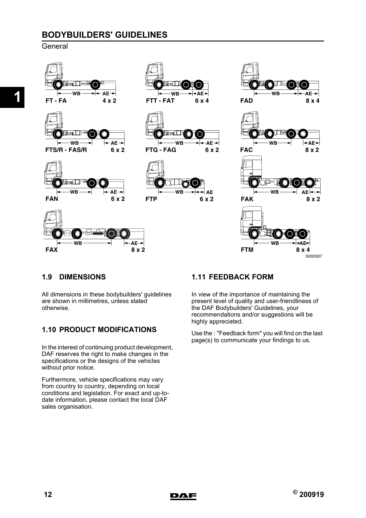
The opening chapter sets the rules of the game: the purpose of the guidelines, who to contact, the verification process for superstructures, statutory requirements, vehicle specification and layout drawings, weight distribution (including the 20% front-axle and 25% driven-axle minimums for solo and combination use), lateral stability, periods of bodying and storage, the full DAF vehicle range with LF45, LF55, CF65, CF75, CF85 and XF105 descriptions, plus the wheelbase and rear overhang designations used throughout the book. Dimensions are in millimetres unless stated otherwise.
Chapter 2 – Chassis Information
This is the hands-on fabrication chapter. It covers levelling the chassis (including the three adjustable supports required for air-suspended chassis), drilling holes (with the minimum B>3×D and C>70 mm truck / 50 mm tractor rules and the 45° deburring requirement), welding on the chassis, cab and superstructure with the specific disconnect and earth-terminal instructions, modifying the rear overhang (500 mm maximum extension, 60% of wheelbase limit), wheelbase modifications, attachment of components to the chassis with the tightening-torque table for DAF flange bolts, replacing rivets by bolts, inlet and exhaust systems, the fuel system including extra-tank connection methods, chassis and cabine related dimensions, the drawbar cross member (with D, Dc and V value formulas and the full cross-member data table), rear light brackets, wheel mounting torques, wheel clearance, mudguard location, EC-approved rear underrun protection, and automatic lubrication.
Chapter 3 – General Information on Superstructures
Every superstructure rests on the rules in this chapter. It explains when a sub-frame is required and how to build one (channel sections, tapered front ends, 1200 mm maximum cross-member spacing, 0.6H minimum cross-member height, filler rules), then documents the five DAF Body Attachment Methods — BAM 1 (fully non-rigid), BAM 2 (rigid at front), BAM 3a/3b (rigid at rear), BAM 4 (fully rigid) and BAM 5 (console attachment) — with the tie rod, console, attachment plate and console-model-B techniques fully described. It includes the first attachment point rules, the type-of-superstructure / BAM matrix, and then vehicle-specific BAM diagrams and attachment counts for FA LF45, FA LF55, FA CF65, FA CF/XF, FAR/FAS, FAG, FAN, FAT, FAC/FAX, FAD and FAK chassis.
Chapter 4 – Superstructures
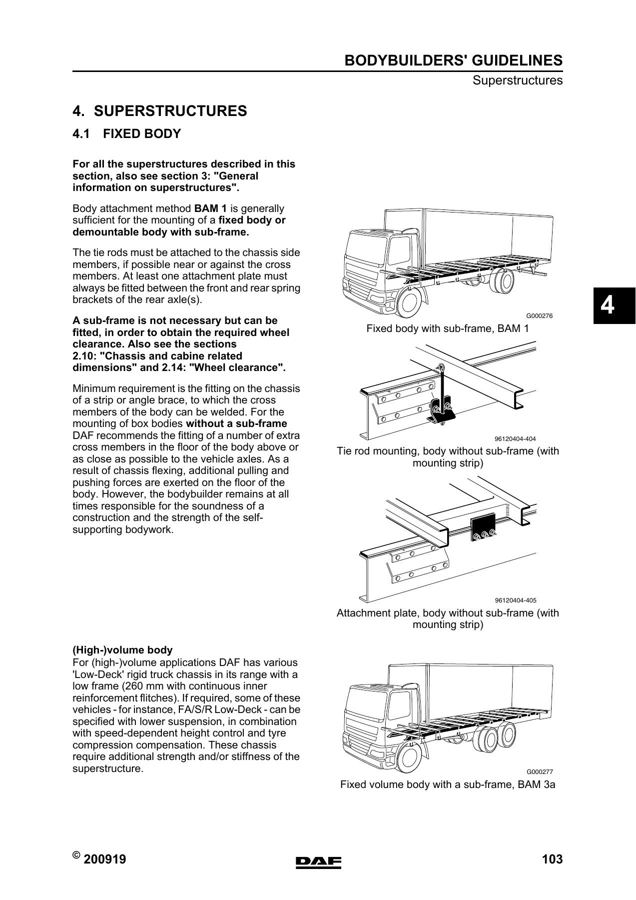
Body-type-specific guidance for the most common upfits. Fixed bodies (including (high-)volume bodies with low-deck chassis and the twist-lock position rules), bodies with tail lifts (with sub-frame dimension tables up to 2000 kg capacity and BAM 3b/BAM 3 guidance), vehicle loading cranes (crane-behind-cab vs crane-at-rear-end BAM selection, crane-base attachment, sub-frame dimension graphs A and B, torsional stability), tipper bodies (front-end ram, central ram, three-way and tipping demountable, with sub-frame dimension tables), tankers (sub-frame, console-fixed, semi-flexible, all-flexible and three-point attachments), concrete mixers and pumps, public utility vehicles (refuse collectors, rotating drum, road sweeper, gully emptier) and fifth wheel mounting (KA/HK dimensions, D value formula, base plate bolt rules).
Chapter 5 – Cab Information
Cab modification rules, the maximum permissible additional cab weights for LF, CF and XF cabs (roof, bunk, under-bunk and storage compartment limits with illustrations), accessories mounting positions for roof spoilers, beacons, aerials and spotlights, and the correct procedure for setting the roof spoiler height.
Chapter 6 – PTO and Other Energy Consumers
The complete PTO selection and installation chapter. It opens with ZF, Eaton and Allison gearbox ratio tables, then covers the PTO specification rules (torque classes, protection, oil temperature limits, the torque and output calculation formulas), clutch-independent PTOs (front-end direct and indirect, crankshaft pulley, coolant pump pulley, generator and hydraulic pump preparations, engine PTO, flywheel PTO), clutch-dependent PTOs with first-PTO and second-PTO tables for every gearbox variant, transfer box PTO, PTO operation, the compressed air system with permitted air-consumption limits and connection points, air feed for tipper preparation, and the engine heating system with the coolant circuit diagram.
Chapters 7 to 11 – Electrical Systems and Data Communication
Chapter 7 lays out the general electrical rules: circuit diagram marking, the two main earth points and the M-wire / 9000-wire distinction, wire cross-section and fuse sizing tables, battery charging, peak voltage protection, EMC compatibility, maximum additional electrical load per chassis, additional batteries and alternators, connection points and permitted power loads, dashboard switches, automated and automatic gearbox integration, retarders, taillift preparation, axle load monitoring and the customer parameter change form. Chapter 8 covers data communication — CAN SAE J1939 / ISO 11898 including FMS, CANopen, ISO 11992/2 & /3, the Body Builders’ Module, CVSG gauges and Body Builders’ CAN. Chapters 9, 10 and 11 then apply all of this to the LF, CF and XF series respectively, with cab switch locations, bulkhead connections, chassis connections, ESC control, FMS systems, PTO control and trailer connection points for each range.
Chapter 12 – Application Connector (Code) Number List
Pin-by-pin reference for every application connector in the LF, CF and XF electrical architecture — 1M, 1P, 3L, 3P, 4C, 4D, 12C, 12D, 23K, 56A, 182C, 183C, 238C, A000 through A140, and D347/D365. Each entry lists connector/pin, wire number, description, active-low/active-high state and the corresponding ECU pin where applicable.
Chapter 13 – Part Numbers
The parts chapter lists DAF part numbers for the hardware the guidelines reference: mountings (tie rods, attachment plates, mounting brackets, consoles, cross-connecting members, cab suspension springs for top-sleeper mounting), flange bolts and nuts, electrical connector parts (cab and bulkhead), electric cable contour lights, LF mud guard extension pieces, indication lamps, switches, CVSG gauges, air system adapters and couplings, lowered drawbar components, and miscellaneous parts including chassis sections, fuel system couplings, converters, relays, PTO flanges and fifth wheel base plates.
Who This DAF Bodybuilder Guidelines Manual Is For
This is not a driver’s handbook and it is not a workshop repair manual for the engine or gearbox. It is the engineering interface document between DAF and the bodybuilder. That means it is written for the people who actually bolt, weld, cut, wire and certify a body onto a DAF chassis: commercial vehicle bodybuilders and converters, fleet workshops that carry out in-house upfitting, trailer and superstructure manufacturers, DAF dealer technical staff who sign off on body installations, and engineers responsible for compliance with the statutory requirements that apply in the country of registration. If your work touches the chassis, the sub-frame, the attachment points, the PTO, the compressed air take-off or the body electrical interface on an LF, CF or XF105, this document is the one that tells you what is permitted and what will void the vehicle’s conformity.
Why the DAF LF CF XF105 Bodybuilder Guidelines Matter
Mounting a body is not simply a matter of putting steel on steel. The DAF chassis is designed to flex, and every rule in this manual exists because getting it wrong has consequences — cracked side members from an un-approved weld, cracked flanges from a bolt fitted through a flange, reduced vehicle stability from a mis-positioned centre of gravity, a brake system that no longer meets ECE-R13 because an air consumer was tapped off the wrong port, or a CAN network that drops out because a third-party device was wired to the wrong earth. The BAM system, the minimum and maximum attachment distances, the 1200 mm cross-member rule, the 60% wheelbase rear-overhang limit and the 4% left/right wheel weight tolerance are all there to protect the vehicle, the load and the driver.
Equally important, the electrical chapters in this DAF LF CF XF105 Bodybuilder Guidelines manual exist because modern DAF trucks are network vehicles. The VIC, DIP, BBM, ECS/ DMCI engine management and AS-Tronic gearbox all talk over CAN, and there are only certain points where a bodybuilder is allowed to tap in. The application connector lists in Chapter 12 give the exact wire number and pin for every permitted interface, so you can wire a tipper, refuse body, crane, tail lift or tanker without disturbing the vehicle’s own systems. That is what turns a body installation from a risk into a documented, repeatable job.
IMAGES PREVIEW
Instant PDF Delivery – Print It, Search It, Take It to the Truck
The DAF LF CF XF105 Bodybuilder Guidelines 2009-19 is delivered as an instant-download PDF after checkout — no shipping, no waiting for a paper copy, no risk of a lost binder. The file is 378 pages covering the full LF, CF and XF105 upfit process, and it opens on any device: workshop PC, laptop, tablet or phone. Print the chapters you need for the job and keep the rest on file. If you are quoting a body installation, planning a sub-frame, checking a BAM attachment count, selecting a PTO, running a body electrical interface or verifying a drawbar cross-member rating, the information is in your hand the moment payment clears. Add it to your technical library today and work from the same guidelines DAF gives its own bodybuilding industry.

Reviews
There are no reviews yet.