Description
Iveco New Daily E6 Bodybuilder Instructions Manual 2017 – 692.68.675
This Iveco New Daily E6 Bodybuilder Instructions manual is the complete 2nd edition document, published under number 692.68.675 in October 2017 by IVECO S.p.A. It provides the technical information, features and instructions required for the transformation and fitting of the New Daily E6 vehicle. Written for qualified and specialised staff, it covers everything from chassis modifications and superstructure applications to power take-offs, electronic subsystems, AdBlue system relocation and the Expansion Module. Whether you are fitting a tipper body, installing a crane, modifying the wheelbase, or integrating additional electrical equipment, this manual sets out the approved procedures and the limits within which those modifications must remain.
File Details
- Manual type: Bodybuilder Instructions / Transformation and Fitting Guidelines
- Brand: IVECO
- Model: New Daily E6
- Document number: 692.68.675
- Edition: 2nd Edition – Base 10/2017
- Date: October 2017
- Language: English
- Page count: 276
- File format: PDF
Chapters Covered
- Section 1 – General Information: scope of guidelines, electronic documentation, IVECO authorisation, authorisation requests, responsibilities, legislative requirements, multi-stage type approval, warranties, quality system management, accident prevention, materials and recycling, vehicle management, vehicle names, identifications, dimensions and ground, fire risk prevention
- Section 2 – Chassis Interventions: general chassis modification standards, drills on the chassis, rust and paint protection, wheelbase modification, rear overhang modification, installing the tow hook, assembling an additional axle, gearbox modification, work on suspensions, engine air intake and exhaust modifications, engine cooling system modifications, heating/conditioning plant modifications, bodywork interventions, changing tyre size, work on the braking system, electrical system current interventions and draws, part relocation and anchorage, transport of hazardous materials (ADR), installing a retarder, rear under-run protection, rear mudguards and wheel arches, rain flap, side protections
- Section 3 – Applications of Superstructures: construction of the subframe, elements making up the subframe, connection between chassis and subframe, container application, tractor for semi-trailer, transport of inseparable materials, installation of tanks and loose material containers, installing a crane, installation of tail lifts, tilt beds, vehicles for council/fire service and special uses, front installation of snow plough attachments, application of a winch, special outfits
- Section 4 – Power Take-offs: general specifications, PTO on the gearbox, PTO from transfer box, PTO from drive line, PTO on the engine, settings (PTO management, Multiple State Switch)
- Section 5 – Electronic Sub-systems: electronic system, bodybuilder connectors, electronic control units, electrical system (ground points, electromagnetic compatibility), receiver-transmission system, additional equipment (batteries, alternators), current draws, miscellaneous (additional circuits, wheelbase/overhang interventions, trailer pre-installation, side marker lamps, centralised rear door lock, anti-theft system)
- Section 6 – AdBlue and SCRT System: general information, nitrogen oxide catalytic reduction principle, instructions, moving AdBlue system components, type-approved layouts
- Section 7 – Expansion Module: PTO management, wiring diagram, additional functions (Run-Lock, Safety/Alarm, Additional Lights)
- Appendix A – Transport of People: chassis, securing the body, bodywork construction, soundproofing, heated insulation and climate control, current draws, bodybuilder connectors, road tests, underbody stiffener for Daily Minibus
- Appendix B – CNG Natural Power: general information, main safety standards, general specifications, emptying the gas circuit, power take-offs, connectors for bodybuilders, additional alternator
- Appendix C – Hi-MATIC Automatic Gearbox: general information, layout, requirements, warning indicators
Across these sections the manual delivers a complete framework for legally and technically correct vehicle transformation. It explains the limits of permitted masses and centre-of-gravity calculations, the approved methods for drilling, welding and reinforcing the chassis, the correct way to connect a subframe to the chassis for different body types, and the electrical interfacing rules that preserve the vehicle’s functional integrity and warranty. Dedicated chapters address the specific requirements of tippers, cranes, tail lifts, tankers, aerial platforms, and people-transport conversions. Later sections provide the detail needed when the AdBlue system must be relocated or when the Expansion Module is used to manage PTOs and additional functions.
Complete PDF Bookmark Tree
Complete Bookmarks
The complete bookmarks in the “Iveco New Daily E6 Bodybuilder Instructions Manual 2017 – 692.68.675 PDF” are as follows:
+NEW DAILY E6p. 1
UPDATE DATAp. 3
INTRODUCTIONp. 4
SYMBOLS – WARNINGSp. 4
INDEX OF SECTIONSp. 5
+Section 1 – GENERAL INFORMATIONp. 7
Contentsp. 9
1.1 SCOPE OF THE GUIDELINESp. 11
1.2 TECHNICAL DOCUMENTATION AVAILABLE ELECTRONICALLYp. 11
1.3 IVECO AUTHORISATIONp. 11
1.4 AUTHORISATION REQUESTp. 12
1.5 RESPONSIBILITIESp. 12
1.6 LEGISLATIVE REQUIREMENTSp. 12
1.7 MULTI STAGE TYPE APPROVAL – COLLABORATION (only for vehicles registered in the EU, Switzerland and Turkey)p. 12
1.8 WARRANTIESp. 13
1.9 QUALITY SYSTEM MANAGEMENTp. 14
1.10 ACCIDENT PREVENTIONp. 14
1.11 CHOICE OF MATERIALS TO USE: ECOLOGY – RECYCLINGp. 14
+1.12 VEHICLE MANAGEMENT ON THE PART OF BODYBUILDERp. 15
Acceptance of chassisp. 15
Maintenancep. 15
Delivery of the vehicle to the final customerp. 15
+1.13 VEHICLE NAMESp. 16
1.14 IDENTIFICATIONSp. 17
+1.15 DIMENSIONS AND GROUNDp. 17
General informationp. 17
+Determination of the centre of gravity of the superstructure and the payloadp. 18
Height of centre of gravityp. 19
Adoption of stabiliser barsp. 21
+Respect of the permitted massesp. 21
Variations on permitted massesp. 21
1.16 INSTRUCTIONS FOR PROPER FUNCTIONING OF THE VEHICLE PARTS AND ACCESSIBILITYp. 22
1.17 GENERAL REGULATION FOR THE PREVENTION OF FIRE RISKp. 22
1.18 CONVENTIONSp. 23
+Section 2 – CHASSIS INTERVENTIONSp. 25
Contentsp. 27
+2.1 GENERAL CHASSIS MODIFICATION STANDARDSp. 29
+Preventive measuresp. 29
Precautions for alternators and electric/electronic componentsp. 30
Earth connectionp. 30
Braking and electrical systemsp. 30
Characteristics of the material used in chassis modificationsp. 30
Stresses on the chassisp. 32
+2.2 DRILLS ON THE CHASSISp. 32
Hole position and sizep. 32
Screws and nutsp. 33
+Weldsp. 33
Sealing holes by weldingp. 35
+2.3 RUST AND PAINT PROTECTIONp. 35
Original vehicle partsp. 35
Added or modified partsp. 37
+Precautionsp. 38
a) On the vehiclep. 38
b) On engines and their electric and electronic componentsp. 38
+2.4 WHEELBASE MODIFICATIONp. 39
General informationp. 39
Authorisationp. 39
Effects on steeringp. 39
Effects on brakingp. 40
+Intervention procedurep. 40
Additional informationp. 40
Checking chassis stressp. 40
Cross membersp. 41
Reinforcements on the chassisp. 41
Gearbox modificationsp. 42
+2.5 REAR OVERHANG MODIFICATIONp. 42
General informationp. 42
Authorisationp. 43
Chassis Shorteningp. 43
Elongationp. 43
+2.6 INSTALLING THE TOW HOOKp. 44
General informationp. 44
Precautions for Installationp. 45
Types of hookp. 47
Drawbar couplings for centre axle trailersp. 47
Rear crossbar in lowered positionp. 48
2.7 ASSEMBLING AN ADDITIONAL AXLEp. 50
+2.8 GEARBOX MODIFICATIONp. 50
+Lengths allowedp. 50
Positioning the sectionsp. 53
+2.9 WORK ON SUSPENSIONSp. 55
Modification or replacement of stabilising barsp. 55
+2.10 MODIFYING THE ENGINE AIR INTAKE AND EXHAUST SYSTEMSp. 55
Intakep. 56
Engine exhaustp. 56
2.11 MODIFYING THE ENGINE COOLING SYSTEMp. 57
+2.12 MODIFICATIONS TO THE HEATING/CONDITIONING PLANTp. 57
+Installing an additional heating systemp. 57
a) Water heatersp. 58
b) Air heatersp. 58
Installing an air conditioning systemp. 60
+2.13 BODYWORK INTERVENTIONSp. 61
General informationp. 61
Work on cab versionp. 62
Work on van vehiclesp. 65
Protection of occupantsp. 69
+2.14 CHANGING TYRE SIZEp. 70
+2.15 WORK ON THE BRAKING SYSTEMp. 71
General informationp. 71
+Brake pipesp. 71
Metal pipesp. 72
Plastic pipesp. 72
Preparation and assembly (IVECO STD 17-2403)p. 72
Vehicle pipe installationp. 73
EVSC (Electronic Vehicle Stability Control)p. 74
+EVSC system deratingp. 76
Variation of GVWp. 76
Wheelbase variationp. 76
Modification or replacement of suspensionsp. 76
Changing tyresp. 77
2.16 ELECTRICAL SYSTEM: CURRENT INTERVENTIONS AND DRAWSp. 77
2.17 PART RELOCATION AND ANCHORAGE OF ADDITIONAL UNITS AND EQUIPMENTp. 77
2.18 TRANSPORT OF HAZARDOUS MATERIALS (ADR)p. 79
2.19 INSTALLING A RETARDERp. 79
2.20 REAR UNDER-RUN PROTECTION (RUP)p. 80
2.21 REAR MUDGUARDS AND WHEEL ARCHESp. 80
2.22 RAIN FLAPp. 82
2.23 SIDE PROTECTIONSp. 82
+Section 3 – APPLICATIONS OF SUPERSTRUCTURESp. 83
Contentsp. 85
+3.1 CONSTRUCTION OF THE SUBFRAMEp. 87
Materialp. 87
+Sizing of profilesp. 87
Aluminium subframep. 89
+3.2 ELEMENTS MAKING UP THE SUBFRAMEp. 90
Longitudinal profilesp. 90
+Cross membersp. 92
Stiffening of the counter chassisp. 92
Self-supporting superstructures with counter chassis functionsp. 93
+3.3 CONNECTION BETWEEN CHASSIS AND SUBFRAMEp. 93
Choosing the type of connectionp. 93
Connection characteristicsp. 94
Connection with bracketsp. 94
Connections with greater elasticityp. 95
Connections with clevis fasteners or clampsp. 96
Connection with longitudinal and transverse sealing plates (rigid junction)p. 97
Mixed connectionp. 98
+3.4 CONTAINER APPLICATIONp. 98
Fixed bodiesp. 98
+Implementing van versionsp. 99
Front wallp. 100
Vans integrated with the cabp. 100
Tipper bodiesp. 100
+3.5 TRACTOR FOR SEMI-TRAILERp. 102
Fifth wheel supporting structurep. 102
Fifth wheelp. 103
Brake systemp. 103
Tractor and semi-trailer combinationp. 104
3.6 TRANSPORT OF INSEPARABLE MATERIALS (TRAILER TRUCKS)p. 104
3.7 INSTALLATION OF TANKS AND LOOSE MATERIAL CONTAINERSp. 104
+3.8 INSTALLING A CRANEp. 106
Crane behind cabp. 107
Cranes on rear overhangp. 108
Removable cranesp. 110
3.9 INSTALLATION OF TAIL LIFTSp. 110
3.10 TILT BEDS (BREAKDOWN RECOVERY)p. 112
3.11 VEHICLES FOR COUNCIL, FIRE SERVICE AND SPECIAL USESp. 113
3.12 FRONT INSTALLATION OF SNOW PLOUGH ATTACHMENTSp. 113
3.13 APPLICATION OF A WINCHp. 113
+3.14 SPECIAL OUTFITSp. 114
Cowl chassis versionsp. 114
Motor homep. 114
+Installation of aerial platformsp. 114
Aerial platforms on 33S-35S vehiclesp. 115
+Section 4 – POWER TAKE-OFFSp. 117
Contentsp. 119
4.1 GENERAL SPECIFICATIONSp. 121
+4.2 POWER TAKE-OFF ON THE GEARBOXp. 123
Direct installation of a user onto the PTOp. 124
4.3 POWER TAKE-OFF FROM TRANSFER BOXp. 124
4.4 POWER TAKE-OFF FROM DRIVE LINEp. 124
4.5 POWER TAKE-OFF ON THE ENGINEp. 125
+4.6 SETTINGSp. 126
+PTO management on gearboxp. 127
Adjust the engine speed for removing the enginep. 127
Multiple State Switchp. 128
+Section 5 – ELECTRONIC SUB-SYSTEMSp. 131
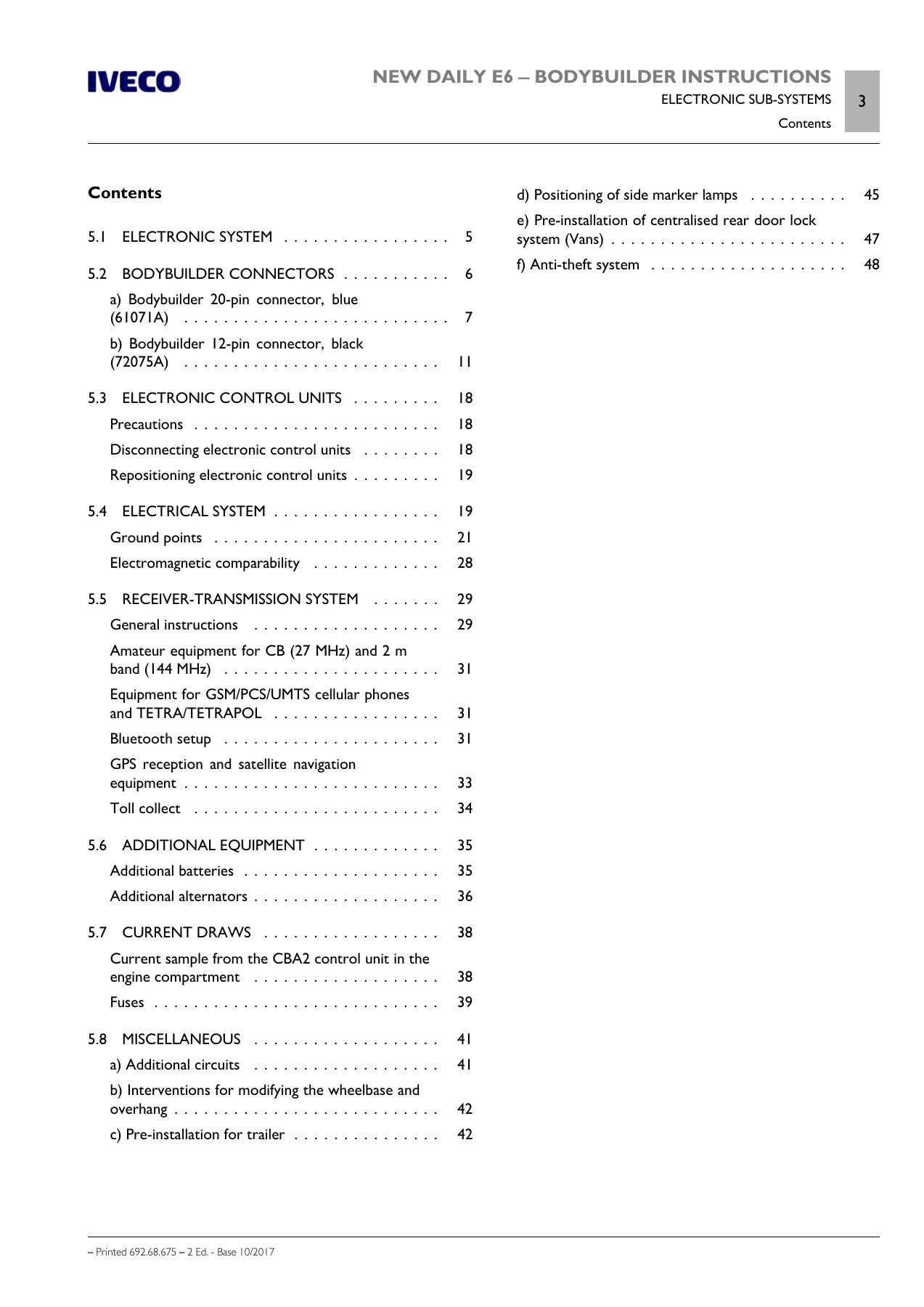
Contentsp. 133
5.1 ELECTRONIC SYSTEMp. 135
+5.2 BODYBUILDER CONNECTORSp. 136
a) Bodybuilder 20-pin connector, blue (61071A)p. 137
b) Bodybuilder 12-pin connector, black (72075A)p. 141
+5.3 ELECTRONIC CONTROL UNITSp. 148
Precautionsp. 148
Disconnecting electronic control unitsp. 148
Repositioning electronic control unitsp. 149
+5.4 ELECTRICAL SYSTEMp. 149
Ground pointsp. 151
Electromagnetic comparabilityp. 158
+5.5 RECEIVER-TRANSMISSION SYSTEMp. 159
General instructionsp. 159
Amateur equipment for CB (27 MHz) and 2 m band (144 MHz)p. 161
Equipment for GSM/PCS/UMTS cellular phones and TETRA/TETRAPOLp. 161
Bluetooth setupp. 161
GPS reception and satellite navigation equipmentp. 163
Toll collectp. 164
+5.6 ADDITIONAL EQUIPMENTp. 165
Additional batteriesp. 165
Additional alternatorsp. 166
+5.7 CURRENT DRAWSp. 168
Current sample from the CBA2 control unit in the engine compartmentp. 168
Fusesp. 169
+5.8 MISCELLANEOUSp. 171
+a) Additional circuitsp. 171
b) Interventions for modifying the wheelbase and overhangp. 172
c) Pre-installation for trailerp. 172
d) Positioning of side marker lampsp. 175
e) Pre-installation of centralised rear door lock system (Vans)p. 177
f) Anti-theft systemp. 178
+Section 6 – ADBLUE AND SCRT SYSTEMp. 181
Contentsp. 183
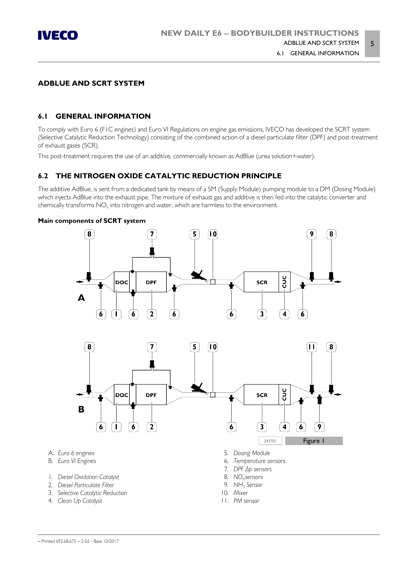
6.1 GENERAL INFORMATIONp. 185
6.2 THE NITROGEN OXIDE CATALYTIC REDUCTION PRINCIPLEp. 185
+6.3 INSTRUCTIONSp. 186
Materialsp. 186
+AdBlue tankp. 186
AdBlue refuelling fillerp. 188
+6.4 MOVING ADBLUE SYSTEM COMPONENTSp. 188
Representative vehiclesp. 189
AdBlue pipep. 190
AdBlue tankp. 191
AdBlue refuelling inletp. 192
+6.5 TYPE-APPROVED LAYOUTSp. 193
Position of the AdBlue tankp. 204
+Section 7 – EXPANSION MODULEp. 205
Contentsp. 207
General informationp. 209
+7.1 PTO MANAGEMENTp. 210
Standard configuration of the PTOp. 210
+Customized PTO configurationsp. 210
a) Engagement restrictionsp. 211
b) Disengagement conditionsp. 211
c) Checks on the enginep. 213
Standard parameters for PTO1 supplied by IVECOp. 214
+Parameters can only be set for PTO2p. 215
a) Engagement Timeoutp. 215
b) Disengagement Timeoutp. 216
+7.2 WIRING DIAGRAMp. 216
Optional connectors for Expansion Modulep. 216
20-pin connector, black (61071B)p. 216
12-pin EM connector, black (72075B)p. 218
9-pin EM connector, yellow (72071)p. 220
12-pin EM connector, black (ST13)p. 221
Electrical connections for PTO2 connectionsp. 222
+7.3 ADDITIONAL FUNCTIONSp. 223
Compatibility between PTO and additional functionsp. 223
+1. Run-Lockp. 224
Connectionsp. 224
”Run-Lock” engagement procedurep. 224
”Run-Lock” disengagement procedurep. 225
+2. Safety/Alarm functionp. 225
Connectionsp. 225
Flashing of low/high beam headlightsp. 226
Speed limitp. 227
+3. Additional Lightsp. 227
Connectionsp. 227
a) Additional lights 1p. 229
b) Additional lights 2p. 230
c) Scene lightsp. 230
d) Rear lightsp. 230
+Appendix A – TRANSPORT OF PEOPLEp. 231
Contentsp. 233
+A.1 CHASSISp. 235
Transportp. 235
Lifting for transport by ship, train. etc.p. 235
Deliveryp. 235
Storagep. 235
Weights and weighingp. 235
A.2 GENERAL STANDARDS FOR SECURING THE BODY TO THE CHASSISp. 236
+A.3 BODYWORK CONSTRUCTIONp. 236
Main dimensionsp. 236
Internal configuration and vehicle capacityp. 236
Driver's seat characteristicsp. 236
Requirements of materials relating to fire protection (R118.01)p. 237
Structure and securing the seat mountsp. 237
Rear baggage compartmentp. 240
Side accessp. 240
Replicated structure and securing handrailsp. 240
Wheelchair lift for disabled passengersp. 241
+A.4 SOUNDPROOFINGp. 241
External noisep. 241
Internal noisep. 241
Soundproof insulationp. 241
+A.5 HEATED INSULATION AND CLIMATE CONTROLp. 242
Insulation for cold climatesp. 242
High temperaturesp. 242
+A.6 CURRENT DRAWSp. 243
People carrier, CBA versionp. 243
A.7 BODYBUILDER CONNECTORSp. 244
A.8 ROAD TESTSp. 246
+A.9 UNDERBODY STIFFENER FOR DAILY MINIBUSp. 246
Requirementsp. 247
Additional elementsp. 248
ATTACHMENT 1 – Structure stiffening kit (opt. 77416)p. 249
+Appendix B – CNG – NATURAL POWERp. 253
Contentsp. 255
B.1 GENERAL INFORMATIONp. 257
+B.2 MAIN SAFETY STANDARDSp. 257
During refuelling operationsp. 257
In the event of gas leaksp. 258
In the event of a firep. 258
+B.3 GENERAL SPECIFICATIONSp. 258
Shut-off and safety valvesp. 259
gas pipesp. 259
Repainting outfitted chassisp. 259
+B.4 EMPTYING THE GAS CIRCUITp. 260
a) Partial emptyingp. 260
b) Emptying fullyp. 261
B.5 POWER TAKE-OFFSp. 263
B.6 CONNECTORS FOR BODYBUILDERSp. 263
B.7 ADDITIONAL ALTERNATORp. 265
+Appendix C – Hi-MATIC AUTOMATIC GEARBOXp. 267
Contentsp. 269
C.1 GENERAL INFORMATIONp. 271
C.2 LAYOUTp. 271
+C.3 REQUIREMENTSp. 272
Gearbox release leverp. 272
Bowden cablep. 272
Propeller shaftp. 273
Rear cross memberp. 273
Coolingp. 274
Retarderp. 274
+C.4 WARNING INDICATORSp. 275
Gear oil temperaturep. 275
Reverse gear engagement signalp. 275
What This Manual Enables
With this Iveco New Daily E6 Bodybuilder Instructions manual, a bodybuilder or converter can plan and execute a wide range of modifications correctly. You can determine the permissible wheelbase and rear overhang changes, calculate load distribution and centre of gravity, select the right subframe profiles and connection types, and install tow hooks, tail lifts, cranes, tipper bodies and tanks in line with IVECO’s requirements. The manual also supports electrical work — from using the bodybuilder connectors and taking current draws safely, to installing additional batteries and alternators, or integrating a trailer socket and side marker lamps. The Expansion Module chapter explains how to configure PTO management, additional lights, Run-Lock and alarm functions. For vehicles with the SCRT system, the AdBlue chapters show the approved component layouts and the procedures for moving the tank or pipework when the body requires it.
Who This Manual Is For
This document is intended for bodybuilders, converters and specialised workshops that transform the IVECO New Daily E6. It assumes a professional level of technical knowledge and directs the reader to the correct procedures, limits and authorisation requirements. It is also valuable for fleet engineers and technical managers who need to understand what modifications are permissible on the New Daily E6 platform and what documentation or approval each type of intervention requires.
Get Instant Access
The Iveco New Daily E6 Bodybuilder Instructions manual gives you the full bodybuilder guidance for the New Daily E6 in one PDF. Every chassis modification, superstructure connection, electrical interface and AdBlue relocation procedure is documented with the technical values, diagrams and tables you need to work correctly. Having the correct specifications on hand reduces the risk of costly errors, failed inspections or voided warranties. Delivered as an instant PDF download, this manual can be viewed on any device, printed for workshop use, and kept as a permanent reference for every New Daily E6 conversion you undertake.


Reviews
There are no reviews yet.