★ TRUSTED BY 321,897+ PROFESSIONALS WORLDWIDE
🏢
Trusted Business
Verified & Licensed
🛡️
Virus Free Files
100% Safe Downloads
🔒
Secure Payment
SSL Protected
⚡
Instant Delivery
Available Immediately
Sale!

Iveco Eurocargo M.Y. 2008 Bodybuilder Instructions Manual – Chassis Modifications, PTO & SCR Guide

Original price was: $39.95.Current price is: $22.95.

Complete IVECO Eurocargo M.Y. 2008 bodybuilder instructions covering chassis modifications, subframe mounting, PTO installation, electronic systems, and SCR/AdBlue exhaust system procedures. Print 603.95.003, 1st Edition, January 2009.

⚡
Instant PDF Download
Available immediately
💾
Save to Your Device
Download & keep forever
🛡️
Antivirus Scanned
100% virus-free
🌍
Trusted Worldwide
175,000+ customers

Description

IVECO Eurocargo M.Y. 2008 Bodybuilder Instructions

This 237-page manual is IVECO’s official bodybuilder instruction set for the Eurocargo M.Y. 2008 range, published as Print 603.95.003, First Edition, Base January 2009. It is the reference document for bodybuilders, converters, and upfitters who mount bodies, cranes, tippers, tail lifts, tanks, and specialist equipment on Eurocargo chassis, and for those who carry out chassis modifications such as wheelbase changes, rear overhang adjustments, and additional axle installations.

The manual is structured into six sections, each addressing a different area of the conversion process. It provides the dimensional limits, stress values, material specifications, and procedural steps that IVECO requires to preserve vehicle safety, reliability, and warranty coverage after modification.

File Details

  • Manual type: Bodybuilder Instructions / Upfitter Manual
  • Brand: IVECO
  • Model: Eurocargo M.Y. 2008 (ML range)
  • Document number: 603.95.003
  • Edition: 1st Edition — Base January 2009
  • Language: English
  • Page count: 237
  • File format: PDF

Chapters Covered

  • Section 1 — General Specifications: Aim and scope of bodybuilder instructions; IVECO no objection procedures for changes and fittings; liabilities and guarantees; technical documents; trademarks and logos; legal provisions; accident prevention; ecology and recycling; chassis acceptance; vehicle identification; dimensions and weights; centre of gravity determination; permitted weights; maintenance accessibility; quality system management; conventions.
  • Section 2 — Chassis Modifications: General instructions and specific precautions; rust protection and painting; drilling the chassis; screw and nut classes; material characteristics; chassis stresses; welding procedures; closing existing holes; wheelbase modification (authorisation, steering effects, recommended procedure, stress levels, cross members, frame sections); rear overhang modification; towing device installation (conventional, mid-axled trailers, centre-axle trailers, cross member reinforcement); supplementary axle installation (rear, middle, steering axles, suspension, stabilisers, braking); drive line modification (permitted lengths, driveshaft positions); engine air intake and exhaust modifications; engine cooling system; supplementary heating; air-conditioning; cab modifications (roof panel, spoiler, crew cabs); tyre size changes; braking system modifications (pipes, electronic control, air take-off); electrical system; repositioning parts; ADR hazardous goods; retarder brake; rear protection bar; mudguards and wheel boxes; mudflaps; side guards; chocks; front protection; rear view mirrors.
  • Section 3 — Building & Mounting the Structures: Subframes and bodies (steel and aluminium materials, longitudinal section dimensions); elements of the subframe (longitudinal runner profiles, cross members, stiffening); connections between frame and subframe (bracket, elastic, U-bolt, cleat plate, mixed); fitting box-bodies (fixed, tipper, heavy-duty, light-duty, containers); tractors for semitrailers; tanks and bulk material containers; crane installation (behind cab, rear overhang, removable); tail lift installation; interchangeable outfits; van bodies; tippable decks; concrete mixers; municipal and fire-fighting vehicles; snow-removal equipment; winch installation.
  • Section 4 — Power Take-Offs: General specifications (power calculation, transmission design, electrical and pneumatic systems); PTO from gearbox (tested types, torque values, direct pump application); PTO from transfer box; PTO from transmission; PTO from engine (front pulley, rear flywheel Multipower); PTO management (modes 0–3, torque curve limits, intermediate speed governor, standard configurations, clutch-dependent PTO, second speed limiter); isochronous engine control.
  • Section 5 — Special Instructions for Electronic Subsystems: Electronic system layout; bodybuilder connectors (21-pin, 9-pin, FMS, Expansion Module, PTO connectors, ISO trailer couplings); anti-theft device installation; tail lift wiring; FMS; EM (Expansion Module) connections and PTO conditions; electrical system modifications (electromagnetic compatibility, additional equipment, batteries and alternators, power draw-off points, main battery switch, additional circuits, wheelbase/overhang wiring changes, 12V/24V supply, side marker lamps).
  • Section 6 — Special Instructions for SCR Exhaust System: General specifications; nitrogen oxide catalytic reduction principle and AdBlue; on-board instruments; AdBlue distribution; specifications for installation and removal (AdBlue tank positioning, pipes and heating water, supply module position, dosing module, exhaust pipes); wiring for SCR system components; OBD 1 — Stage 2 requirements.

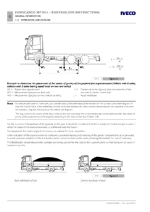
Each section combines text explanations with diagrams, tables, and calculation formulas. The chassis modification section, for example, includes a worked example for determining the longitudinal centre of gravity position with a 12-tonne Eurocargo, and the crane section provides tables that map crane torque against minimum subframe section modulus for each model and wheelbase.

Who This Manual Is For

This Iveco Eurocargo M.Y. 2008 bodybuilder instructions manual is written for skilled and qualified personnel who design, fabricate, and install body structures and ancillary equipment on Eurocargo chassis. It is equally relevant to fleet engineers specifying conversions, workshop managers overseeing chassis modifications, and technicians carrying out the work.

The manual assumes a professional level of technical knowledge and directs the reader to contact IVECO for any modification not explicitly covered. It is not a general repair manual for the vehicle — it is the upfitter’s rulebook for doing conversions the right way.

Why the Bodybuilder Instructions Matter

Eurocargo chassis are engineered with specific load limits, stress tolerances, and material properties. Modifications that exceed these limits — or that are carried out without regard to the procedures in this manual — can compromise vehicle safety, invalidate the warranty, and create liability for the bodybuilder.

The manual gives you the numbers you need: permitted static stress values (120 N/mm² on-road, 80 N/mm² off-road for Eurocargo), minimum section moduli for subframe runners across every wheelbase and model, torque values for PTO installations, maximum driveshaft lengths at given rotational speeds, and braking system pressure limits. It also gives you the procedures: how to cut and weld side members with the correct V-chamfer and reinforcement, how to position a crane so the subframe carries the load correctly, how to extend or shorten AdBlue lines without contaminating the dosing module.

Key Technical Content

Some of the specific data you will find includes:

  • Chassis frame section dimensions and available reinforcement sections from IVECO Spare Parts (Part numbers 1908966 through 1908963, covering 180.5×65×4 mm to 277.9×80×7.7 mm).
  • Maximum wheelbase extension limits per model: 5,670 mm for 60E–120E; 6,570 mm for 120E–160E; 6,700 mm for 180E–190EL; 4,500 mm for 110EW and 150EW.
  • PTO torque values and ratios for ZF and Allison gearboxes, including the ZF S5-42, ZF 6S700, ZF 6S800, ZF 6S1000, ZF 9S-75, ZF 9S-1110, Allison S1000, S2500, and S3000.
  • Engine PTO limits: maximum 400 Nm torque and 0.015 kgm² moment of inertia for Tector E14–E30 engines; maximum bending moment values with angular position multipliers.
  • Braking system pipe specifications: DIN 74324 / Iveco Standard I8-0400, maximum operating pressure 11 bar, minimum bend radius 6× outer diameter.
  • AdBlue pipe maximum lengths: 5 m from tank to supply module, 3 m from supply module to dosing module.
  • Dosing module orientation angles and minimum distance from SCR catalytic converter (1,200 mm for Cursor engines).
  • Electrical system voltage (24V), battery capacities (70 Ah to 170 Ah), alternator outputs (70 A to 90 A), and power draw-off limits.

What You Can Do With This Manual

With the Iveco Eurocargo M.Y. 2008 Bodybuilder Instructions at hand, you can:

  • Plan and execute a wheelbase modification with the correct cutting, welding, and reinforcement procedure.
  • Determine the maximum permissible rear overhang and the required subframe section for a tipper, crane, or tail lift.
  • Install a towing device correctly, including calculating the D-value and V-value for the hook class.
  • Set up a power take-off from the gearbox, engine front pulley, or flywheel, with the correct torque limits and control mode.
  • Wire bodybuilder connectors, PTO switches, and auxiliary circuits without damaging the vehicle’s electronic systems.
  • Reposition or extend SCR system components while maintaining AdBlue system integrity and OBD compliance.
  • Verify that a conversion respects IVECO’s stress limits, weight distribution requirements, and legal regulations.

Complete PDF Bookmark Tree

Complete Bookmarks

The complete bookmarks in the “Iveco Eurocargo M.Y. 2008 Bodybuilder Instructions Manual – Chassis Modifications, PTO & SCR Guide” are as follows:

EUROCARGO M.Y. 2008p. 1
BODYBUILDERS INSTRUCTIONSp. 1
UPDATE DATAp. 3
Forewordp. 5
Symbols – Warningsp. 5
Page header and footer interpretationp. 6
INDEX OF SECTIONp. 7
SECTION 1 – General specificationsp. 9
General specificationsp. 9
1.1 Aim of Bodybuilders instructionsp. 11
1.2 IVECO “no objection” for changes and fittingsp. 11
1.3 Liabilitiesp. 12
1.4 Guaranteesp. 12
1.5 Request for a “no objection”p. 12
1.6 IVECO technical documents available by means of computerp. 13
1.7 Trademarks and logosp. 13
1.8 Legal provisionsp. 13
1.9 Prevention of accidentsp. 14
1.10 Choice of material to use: Ecology – Recyclingp. 14
1.11 Vehicle deliveryp. 15
1.11.1 Advice for acceptance of the chassis by the Fitterp. 15
1.11.2 Vehicle maintenance in the storep. 15
1.11.3 Delivery of the vehicle to the end customerp. 15
1.12 Vehicles identificationp. 16
1.13 Dimensions and weightsp. 17
1.13.1 General specificationsp. 17
1.13.2 Determining the centre of gravity of the body and payloadp. 17
1.13.3 Observing the permitted weightsp. 21
1.14 Instructions for the correct functioning of the parts of the vehicle and accessibility for maintenancep. 22
1.15 Quality system managementp. 23
1.16 Vehicle maintenancep. 23
1.17 Conventionsp. 24
SECTION 2 – Chassis modificationsp. 25
Chassis modificationsp. 25
2.1 General instructions for chassis modificationsp. 29
2.1.1 Specific Precautionsp. 29
2.2 Protection against rust and paintingp. 31
2.2.1 Original componentsp. 31
2.2.2 Added or modified painted partsp. 34
2.2.3 Precautionsp. 35
2.3 Drilling the chassisp. 36
2.3.1 Screws and nutsp. 36
2.3.2 Characteristics of the material to be used when modifying the chassisp. 37
2.3.3 Stresses on the chassisp. 38
2.3.4 Welding the Chassisp. 39
2.3.5 Closing of existing holesp. 41
2.4 Modifying the wheelbasep. 42
2.4.1 General specificationsp. 42
2.4.2 Authorisationp. 42
2.4.3 Effects on the steeringp. 42
2.4.4 Recommended procedurep. 43
2.4.5 Chassis stress levelp. 44
2.4.6 Cross membersp. 44
2.4.7 Sections of chassis frame structural members: Availability with IVECO Spare Partsp. 45
2.4.8 Changes to the transmissionsp. 45
2.5 Modifying the rear overhangp. 46
2.5.1 General specificationsp. 46
2.5.2 Reducing the overhangp. 46
2.5.3 Increasing the overhangp. 46
2.6 Installing a towing devicep. 48
2.6.1 General specificationsp. 48
2.6.2 Conventional tow hooksp. 49
2.6.3 Towhook for mid-axled trailersp. 50
2.6.4 Reinforcements on the chassis frame structural membersp. 52
2.6.5 Reinforcement of standard rear cross memberp. 56
2.6.6 Lowered rear cross memberp. 58
2.6.7 Rear crossmember in low, forward position (short attachment)p. 60
2.6.8 Remarks about the payloadp. 60
2.6.9 Increasing the towable weightp. 60
2.7 Installing a supplementary axlep. 61
2.7.1 General specificationsp. 61
2.7.2 Chassis frame reinforcementp. 61
2.7.3 Application of a rear or central axle on models ML150 and ML180p. 63
2.7.4 Application of a rear axlep. 63
2.7.5 Application of a middle axlep. 64
2.7.6 Steering axlesp. 64
2.7.7 Components and suspensionp. 64
2.7.8 Stabilisersp. 65
2.7.9 Connection to the chassis framep. 65
2.7.10 Braking system for additional axlep. 65
2.7.11 Lifting devicep. 66
2.7.12 Modifying the suspensionp. 66
2.7.13 Conversion from mechanical to pneumatic suspensionp. 66
2.8 Modifying the drive linep. 67
2.8.1 Permitted lengthsp. 67
2.8.2 Determining driveshaft positionsp. 69
2.9 Modifications of the engine air intake and exhaust systemp. 72
2.9.1 Intakep. 72
2.9.2 Engine exhaustp. 72
2.9.3 Alignment of the parts of the exhaust systemp. 73
2.10 Modification of the engine cooling systemp. 81
2.11 Installation of a supplementary heating systemp. 82
2.12 Installing an air-conditioning systemp. 83
2.13 Cab modificationsp. 84
2.13.1 General specificationsp. 84
2.13.2 Roof panel modificationsp. 84
2.13.3 Fitting a spoiler or a top-sleeperp. 85
2.13.4 Construction of crew cabsp. 85
2.14 Changing the size of the tyresp. 87
2.15 Modifications to the braking systemp. 88
2.15.1 General specificationsp. 88
2.15.2 Brake pipesp. 88
2.15.3 Electronic braking system control devicesp. 93
2.15.4 Taking air from the systemp. 93
2.16 Electrical system: modifications and drawing-off powerp. 94
2.17 Repositioning parts and mounting auxiliary assemblies and equipmentp. 94
2.18 Transporting hazardous goods ADRp. 96
2.19 Application of a retarder brakep. 96
2.20 Alterations to the rear protection barp. 97
2.21 Rear mudguards and wheel boxesp. 98
2.22 Mudflapsp. 98
2.23 Side guardsp. 99
2.24 Chocksp. 101
2.25 Front protection (FUP)p. 101
2.26 Rear view mirrorsp. 102
SECTION 3 – Building & mounting the structuresp. 103
Building & mounting the structuresp. 103
3.1 Subframes and bodiesp. 105
3.1.1 Material (steel subframe)p. 105
3.1.2 Material (aluminum subframe)p. 106
3.1.3 Longitudinal section dimensionsp. 107
3.2 Elements making up the subframep. 108
3.2.1 Longitudinal runner profilesp. 108
3.2.2 Cross membersp. 110
3.3 Connections between frame and subframep. 112
3.3.1 Choosing the type of body mountingp. 112
3.3.2 Body mounting characteristicsp. 112
3.3.3 Connection with bracketsp. 114
3.3.4 Connection with greater elasticityp. 116
3.3.5 Connection with U-bolts (clamps)p. 117
3.3.6 Connection with cleate (shear resisting) plates to contain longitudinal and transverse forcesp. 118
3.3.7 Mixed connectionp. 119
3.4 Fitting box-bodiesp. 120
3.4.1 Fixed bodiesp. 120
3.4.2 Tipper bodiesp. 123
3.4.3 Heavy-duty servicep. 125
3.4.4 Light-duty servicep. 126
3.4.5 Containersp. 127
3.5 Tractors for semitrailersp. 128
3.6 Installation of tanks and containers for bulk materialsp. 129
3.7 Installing a cranep. 132
3.7.1 Crane behind the driver’s cabp. 133
3.7.2 Crane on rear overhangp. 138
3.7.3 Removable cranesp. 139
3.8 Installation of tail liftsp. 140
3.9 Interchangeable outfitsp. 145
3.10 Making van bodiesp. 146
3.11 Tippable decksp. 146
3.12 Installation of concrete mixersp. 147
3.13 Vehicles for municipal, fire-fighting and special servicesp. 149
3.14 Installation of snow-removal equipment on front of vehiclep. 149
3.15 Winch installationp. 150
SECTION 4 – Power take-offsp. 151
Power take-offsp. 151
4.1 General Specificationsp. 153
4.2 Power take-off from gearboxp. 155
4.3 Power take-off from the transfer boxp. 158
4.4 Power take-off from transmissionp. 158
4.5 Power take-off from enginep. 159
4.5.1 Taking torque from engine front sidep. 159
4.5.2 Power take off from the rear of the enginep. 161
4.5.2.1 Multipower power take-off on flywheel sidep. 161
4.6 PTO managementp. 163
4.6.1 General specificationsp. 163
4.6.2 PTO Mode 0 (run mode)p. 164
4.6.3 PTO modes 1, 2, 3 configurablep. 164
4.6.3.1 Changes to the torque curve, final rotation speed and steepness of the final limiterp. 166
4.6.4 Intermediate speed rate governorp. 168
4.6.5 Standard configurationsp. 169
4.6.6 Specific indications: correlation between PTO configuration and power take-offs installedp. 170
4.6.7 Power take-off depending on the clutchp. 170
4.6.8 Second speed limiterp. 173
4.7 Electrical systemp. 174
4.8 Pneumatic systemp. 174
4.9 Isochronous control of engine ratep. 174
SECTION 5 – Special instructions for electronic subsystemsp. 177
Special instructions for electronic subsystemsp. 177
5.1 Electronic systemp. 179
5.2 Bodybuilder connectorsp. 180
5.2.1 Positioning inside the cabp. 180
5.2.2 Positioning on the chassisp. 185
5.3 Installation of anti-theft devicesp. 188
5.4 Fitting for tail lift -opt 4113p. 189
5.5 Fitting for tail lift + 2nd ECAS remote control – opt 4115p. 190
5.6 FMSp. 190
5.7 EM (Expansion Module)p. 191
5.7.1 Connectionsp. 192
5.7.2 PTO on/off conditionsp. 193
5.7.3 No PTO or PTO setups installedp. 193
5.7.4 PTO Multipowerp. 193
5.7.5 Manual transmission PTO with electrical engagementp. 194
5.7.6 Allison transmission PTOp. 194
5.8 Electrical system: modifications and drawing-off powerp. 195
5.8.1 General Informationp. 195
5.8.2 Electromagnetic Compatibilityp. 196
5.8.3 Additional equipmentp. 202
5.8.4 Electrical power draw-offp. 205
5.8.5 Main switch of the batteries (optional)p. 208
5.8.6 Additional circuitsp. 209
5.8.7 Operations for changing the wheelbase and the overhangp. 210
5.8.8 Drawing power at a different voltage to that of the systemp. 210
5.8.9 Arrangement of Side Marker Lampsp. 211
SECTION 6 – Special instructions for -SCR- exhaust systemp. 212
Special instructions for -SCR- exhaust systemp. 212
6.1 General specificationsp. 214
6.2 The nitrogen oxide catalytic reduction principle. AdBluep. 215
6.3 On-board instrumentsp. 218
6.4 Distribution of the ecological additive AdBluep. 219
6.5 Specifications for installation and removalp. 220
6.5.1 Operations for positioning the AdBlue tankp. 220
6.5.2 Operations on AdBlue pipes and heating waterp. 222
6.5.2.1 Instructions for lengthening and shortening the AdBlue ducts on the vehiclep. 226
6.5.3 Altering the supply module positionp. 228
6.5.4 Operations on the dosing modulep. 232
6.5.5 Operations on exhaust pipesp. 235
6.6 Wiring for positioning of SCR system componentsp. 236
6.7 OBD 1 – Stage 2p. 237


IMAGES PREVIEW

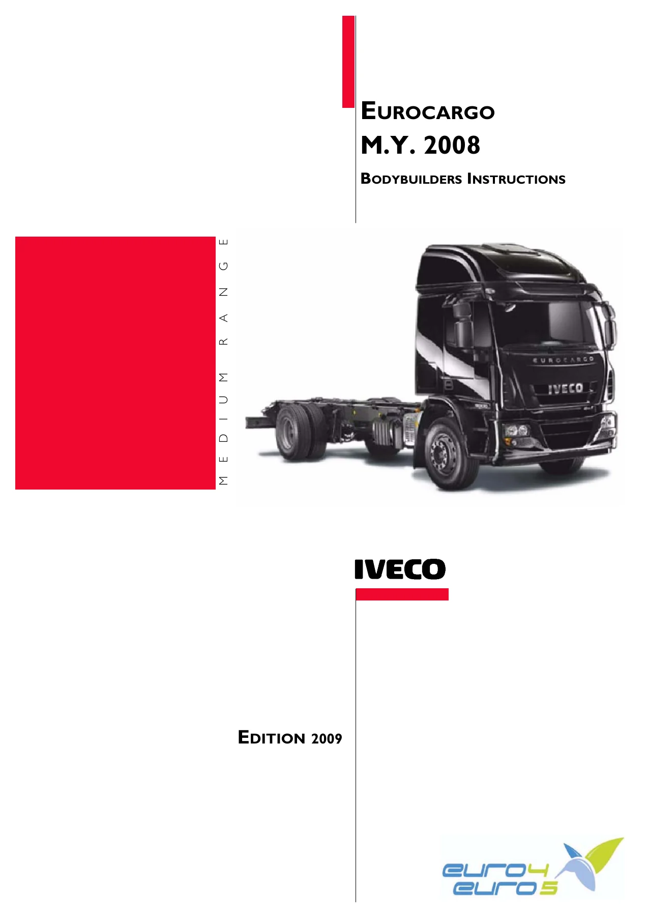
Iveco Eurocargo M.Y. 2008 Bodybuilder Instructions Manual - Chassis Modifications, PTO & SCR Guide — PDF page 1 preview
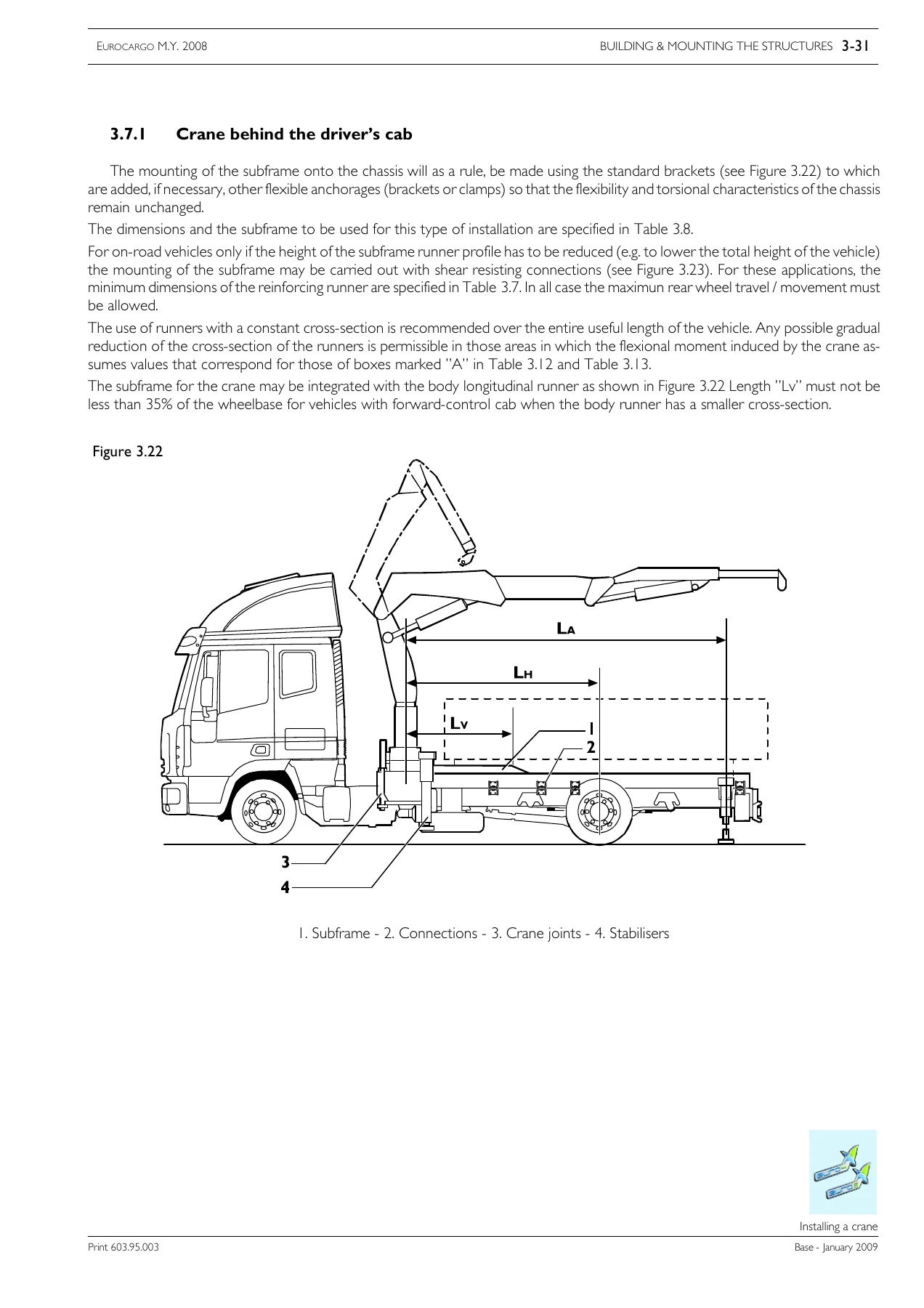
Iveco Eurocargo M.Y. 2008 Bodybuilder Instructions Manual - Chassis Modifications, PTO & SCR Guide — PDF page 133 preview
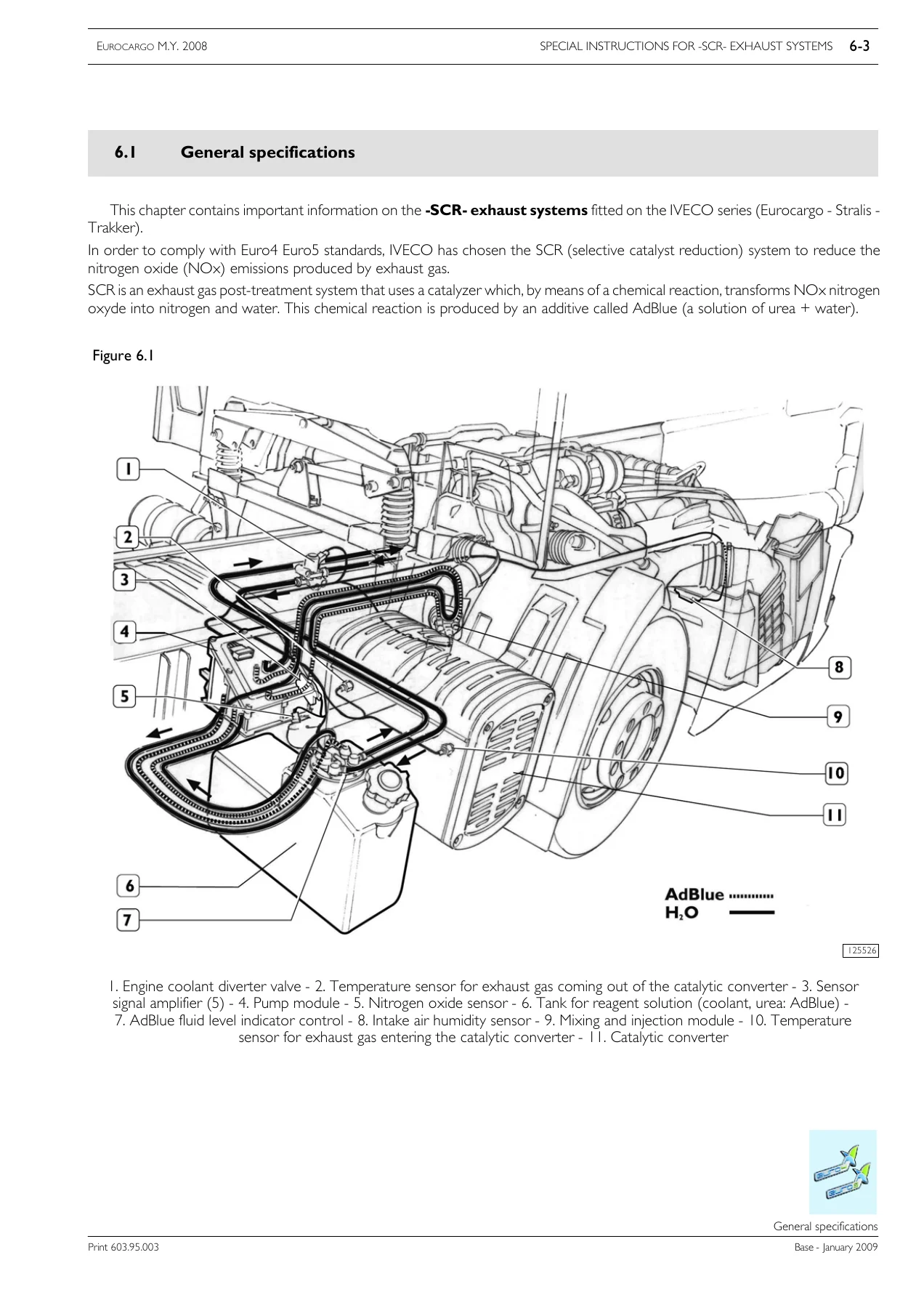
Iveco Eurocargo M.Y. 2008 Bodybuilder Instructions Manual - Chassis Modifications, PTO & SCR Guide — PDF page 214 preview

Instant PDF Delivery

This IVECO Eurocargo M.Y. 2008 Bodybuilder Instructions manual is delivered as an instant PDF download after purchase. No shipping, no waiting. The file can be viewed on any device — desktop, laptop, tablet, or smartphone — and printed for use in the workshop. Keep it on file for reference during every Eurocargo conversion project.

Reviews

There are no reviews yet.

Be the first to review “Iveco Eurocargo M.Y. 2008 Bodybuilder Instructions Manual – Chassis Modifications, PTO & SCR Guide”

What Our Customers Say

★★★★★ Live reviews from customers
Loading customer reviews...
0
    0
    Your Cart
    Your cart is emptyReturn to Shop
    🛒
    Recently Purchased
    🕒 verified order