★ TRUSTED BY 321,897+ PROFESSIONALS WORLDWIDE
🏢
Trusted Business
Verified & Licensed
🛡️
Virus Free Files
100% Safe Downloads
🔒
Secure Payment
SSL Protected
⚡
Instant Delivery
Available Immediately
Sale!

Iveco Eurocargo MY2016 Euro III-V Bodybuilder Instructions Manual 692.68.887

Original price was: $39.95.Current price is: $24.95.

Complete Iveco Eurocargo MY2016 bodybuilder instructions covering Euro III to Euro V chassis, superstructure fitting, PTO installation, electrical interfaces, and AdBlue/SCR system work. Print 692.68.887, first edition, April 2017.

⚡
Instant PDF Download
Available immediately
💾
Save to Your Device
Download & keep forever
🛡️
Antivirus Scanned
100% virus-free
🌍
Trusted Worldwide
175,000+ customers

Description

Iveco Eurocargo MY2016 Euro III-V Bodybuilder Instructions Manual

This is the complete Iveco Eurocargo MY2016 Bodybuilder Instructions publication, document number 692.68.887, first edition, base 04/2017. It is the reference document issued by Iveco for qualified bodybuilders, converters, and specialist workshops who carry out transformation, fitting, and superstructure work on Eurocargo chassis across Euro III, Euro IV and Euro V engine generations. Everything in this Iveco Eurocargo MY2016 Euro III-V Bodybuilder Instructions Manual 692.68.887 is written around the actual chassis architecture of the MY2016 Eurocargo range, from the small 110EL and 120EL models through to the heavier 180E, 190EL and the /P air suspension variants.

File Details

  • Manual type: Bodybuilder Instructions / Conversion and Fitting Guidelines
  • Brand: Iveco
  • Model range: Eurocargo MY2016 (Euro III, Euro IV, Euro V)
  • Document number: 692.68.887
  • Edition: 1st Edition, Base 04/2017
  • Language: English
  • File format: PDF
  • Page count: 231 pages
  • Sections: 6 (General Information, Chassis Interventions, Applications of Superstructures, Power Take-offs, Electronic Sub-Systems, AdBlue and SCR System)

Chapters Covered

  • Section 1 – General Information: Scope of the Guidelines, Technical Documentation Available Electronically, Iveco Authorisation, Authorisation Request, Responsibilities, Legislative Requirements, Multi-Stage Type Approval Collaboration, Guarantees, Quality System Management, Accident Prevention, Choice of Materials (Ecology and Recycling), Vehicle Management on the Part of the Bodybuilder, Vehicle Names, Trademarks and Symbols, Dimensions and Ground, Instructions for Proper Functioning of the Vehicle Parts and Accessibility, General Regulation for the Prevention of Fire Risk.
  • Section 2 – Chassis Interventions: General Chassis Modification Standards, Drills on the Chassis, Rust and Paint Protection, Wheelbase Modification, Rear Overhang Modification, Installing the Tow Hook, Assembling an Additional Axle, Gearbox Modification, Modifying the Engine Air Intake and Exhaust Systems, Work on the Engine Cooling System, Installing an Additional Heating System, Installing an Air Conditioning System, Work on the Cab, Changing Tyre Size, Work on the Braking System, Electrical System Current Interventions and Draws, Part Relocation and Anchorage of Additional Units and Equipment, Transport of Hazardous Materials (ADR), Installing a Retarder, Rear Under-run Protection, Rear Mud Guards and Wheel Arches, Rain Flap, Side Protections, Front Under-run Protection, Rear-view Mirrors.
  • Section 3 – Applications of Superstructures: Construction of the Subframe, Elements Making Up the Subframe, Connection Between Chassis and Subframe, Container Application, Tractor for Semi-Trailer, Transport of Inseparable Materials, Installation of Tanks and Loose Material Containers, Installing a Crane, Installation of Tail Lifts, Interchangeable Outfits, Construction of Box Truck Bodies, Tilt Beds, Vehicles for Council and Fire Service, Front Installation of Snow Plough Attachments, Application of a Winch, Concrete Mixer Installation.
  • Section 4 – Power Take-offs: General Specifications, PTO from Gearbox, Power Take-off from Transfer Box, Power Take-off from Drive Line, Power Take-off from Engine (front and rear), PTO Management, Standard Configurations, EM Expansion Module.
  • Section 5 – Electronic Sub-Systems: Electronic Systems, Bodybuilder Connectors, FMS Fleet Management System, Configurations for Tail Lifts, Operator’s Footboard, Electrical Circuit Modifications, Electrical System Operations, Additional Equipment.
  • Section 6 – AdBlue and SCR System (Euro V versions only): General Information, Nitrogen Oxide Catalytic Reduction Principle, Instructions, Pipes, Positioning the Dosing Module, Wiring for Positioning SCR System Components.

Across its six sections, this Iveco Eurocargo MY2016 Euro III-V Bodybuilder Instructions Manual sets out the approved engineering rules for adding a body, structure or driven equipment to the Eurocargo chassis without compromising the vehicle’s structural, braking or electrical integrity. The document deals with the practical realities of a working conversion shop: where you may and may not drill the side members, what weld preparations are permitted, how to reposition the rear crossbar after a chassis shortening, which vehicles can accept an additional third axle and what reinforcement that requires, and how the bodybuilder-supplied electrical loads must be wired so the multiplex network does not throw faults.

Chassis, Subframe and Superstructure Engineering

The chassis intervention rules in this manual are unusually detailed. Section 2 covers allowable hole positions and diameters on the side member web, minimum edge distances, screw classes and torques, weld preparations with bevel geometry, and the corrosion protection cycles that must be reapplied to any modified area. Wheelbase modification is broken down into extension and shortening cases with specific limits and reinforcement requirements, and there are dedicated chapters for adding a third or steering axle, repositioning or reinforcing the rear crossbar, and installing tow hooks for both conventional and centre-axle trailers. There is also a full treatment of RUP and FUP adjustment, side protections, mudguards and other legislative accessories.

Section 3 then takes the same engineering approach to the superstructure itself. It explains how the subframe is sized for each model, how the chassis-to-subframe connection is chosen between elastic brackets and shear-resistant plates, and how different bodies – fixed box bodies, tipping bodies, tanks, roll-off containers, cranes behind the cab or on the rear overhang, tail lifts, tilt beds, concrete mixers, snowplough attachments and winches – each impose their own reinforcement and connection requirements. Tables give recommended minimum section moduli for each model and wheelbase so the bodybuilder can size the counter-chassis correctly rather than guessing.

Power Take-offs and Vehicle Electronics

Section 4 handles power take-off selection and installation, covering gearbox, transfer box, drive line and front or rear engine PTOs. The manual provides tested torque values for each gearbox/PTO combination, transmission ratio data, driveshaft angle limits, and the maximum permitted lengths of sliding and intermediate shafts. It also explains PTO management through the Expansion Module and VCM, including the different PTO modes and their configurable parameters – torque limiting, overspeed regulation, intermediate engine speed memory, and activation conditions for manual, automated and Allison gearboxes.

Section 5 is the electronics reference. It lists the locations and functions of the Eurocargo control units, documents the Bodybuilder connectors in the cab and on the chassis pin by pin, and covers the base and VEHH tail lift configurations, the operator’s footboard pre-configuration for refuse collection, electrical circuit modification rules, grounding points, electromagnetic compatibility limits, additional batteries and alternators, current draw points, and the safe current limits for added circuits. This is the section a converter will keep coming back to when wiring an added body.

AdBlue and SCR System Work

Section 6 is dedicated to Euro V vehicles and the AdBlue/SCR after-treatment system. It explains the SCR reduction principle, then sets out the restrictions on relocating the supply module, dosing module and AdBlue tank, the maximum intake and pipe lengths, the orientation angles for the dosing module in the exhaust pipe, and the rules for lengthening cables and AdBlue or coolant pipes when the chassis layout changes. This is essential reading before extending a wheelbase on a Euro V Eurocargo, because it defines how far the SCR components may be moved and how the pipes must be routed.

Who This Manual Is For

This Iveco Eurocargo MY2016 Euro III-V Bodybuilder Instructions Manual is aimed squarely at bodybuilders, converters and specialised workshops rather than at the general owner-driver. It assumes the reader is designing or carrying out a conversion project and is responsible for the compliance of the finished vehicle. The content is technical and procedural, with tables, formulas and diagrams rather than step-by-step beginner guidance. Anyone fitting a tipper, crane, tail lift, tank, box body, refuse body, concrete mixer or winch to a Eurocargo, or repositioning an axle, lengthening the wheelbase or rewiring the chassis, will find the specific guidance and the limits they need to stay within.

Complete PDF Bookmark Tree

Complete Bookmarks

The complete bookmarks in the “Iveco Eurocargo MY2016 Euro III-V Bodybuilder Instructions Manual 692.68.887” are as follows:

EUROCARGO MY2016 EURO III – Vp. 1
UPDATE DATAp. 3
INTRODUCTIONp. 4
SYMBOLS – WARNINGSp. 4
INDEX OF SECTIONSp. 5
Section 1 – GENERAL INFORMATIONp. 7
Contentsp. 9
1.1 SCOPE OF THE GUIDELINESp. 11
1.2 TECHNICAL DOCUMENTATION AVAILABLE ELECTRONICALLYp. 11
1.3 IVECO AUTHORISATIONp. 11
1.4 AUTHORISATION REQUESTp. 12
1.5 RESPONSIBILITIESp. 12
1.6 LEGISLATIVE REQUIREMENTSp. 12
1.7 MULTI STAGE TYPE APPROVAL – COLLABORATION (only for vehicles registered in the EU, Switzerland and Turkey)p. 12
1.8 GUARANTEESp. 13
1.9 QUALITY SYSTEM MANAGEMENTp. 14
1.10 ACCIDENT PREVENTIONp. 14
1.11 CHOICE OF MATERIALS TO USE: ECOLOGY – RECYCLINGp. 14
1.12 VEHICLE MANAGEMENT ON THE PART OF BODYBUILDERp. 15
Acceptance of chassisp. 15
Maintenancep. 15
Delivery of the vehicle to the final customerp. 15
1.13 VEHICLE NAMESp. 16
Type approval namep. 16
1.14 TRADEMARKS AND SYMBOLSp. 17
1.15 DIMENSIONS AND GROUNDp. 17
General informationp. 17
Weighing of the chassisp. 17
Vehicle adaptabilityp. 17
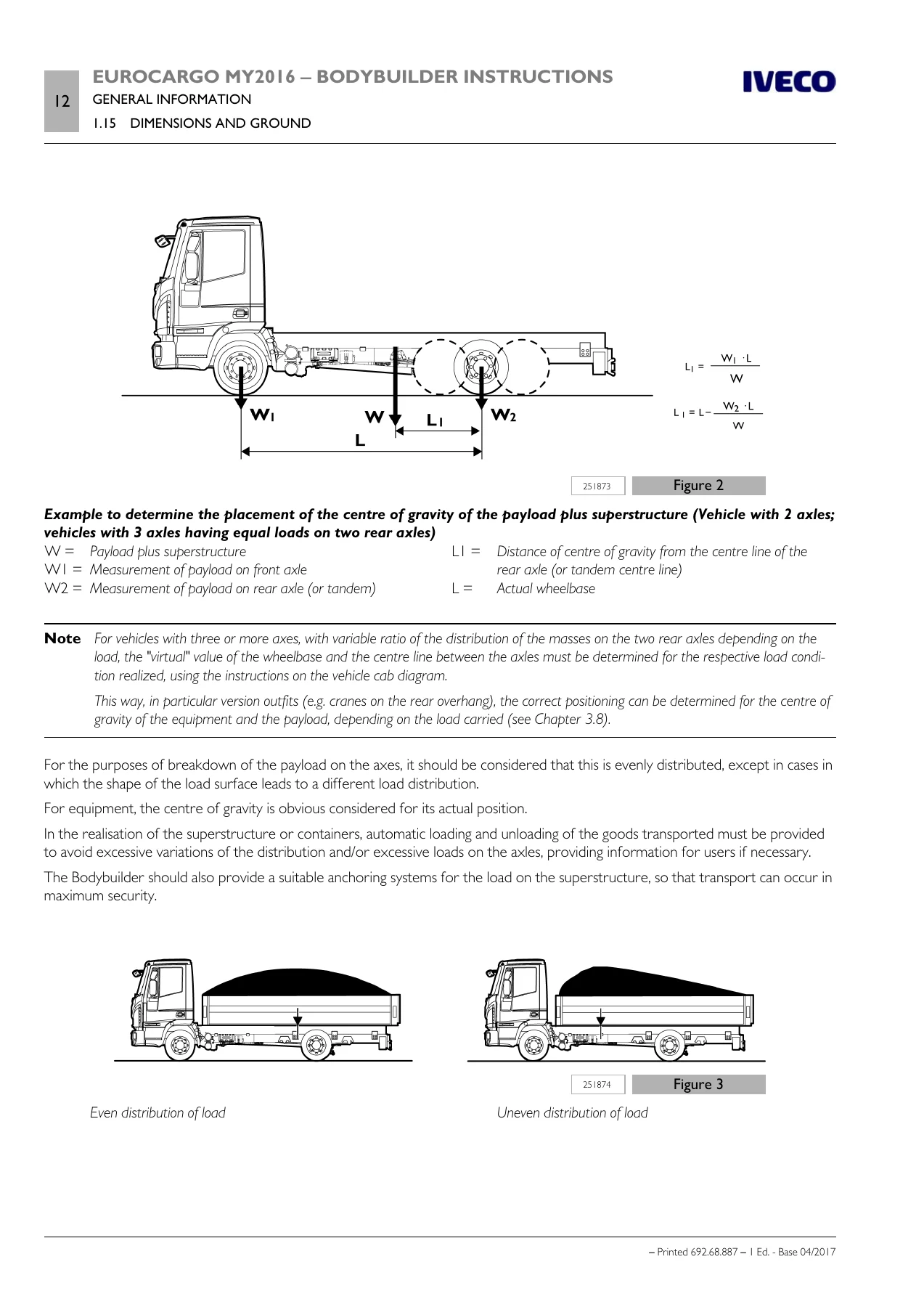
Determination of the centre of gravity of the superstructure and the payloadp. 17
Height of centre of gravityp. 19
a) Fixed loadsp. 19
b) Mobile loadsp. 20
c) Loads that result in increased aerodynamic actionsp. 20
implementation of stabiliser barsp. 20
Respect of the permitted massesp. 20
Variations on permitted massesp. 21
1.16 INSTRUCTIONS FOR PROPER FUNCTIONING OF THE VEHICLE PARTS AND ACCESSIBILITYp. 21
Distance from the exhaust systemp. 23
1.17 GENERAL REGULATION FOR THE PREVENTION OF FIRE RISKp. 23
1.18 CONVENTIONSp. 23
Section 2 – CHASSIS INTERVENTIONSp. 25
Contentsp. 27
2.1 GENERAL CHASSIS MODIFICATION STANDARDSp. 29
Preventive measuresp. 29
Precautions for alternators and electric/electronic componentsp. 30
Braking and electrical systemsp. 30
Characteristics of the material used in chassis modificationsp. 30
Stresses on the chassisp. 31
2.2 DRILLS ON THE CHASSISp. 31
Hole position and sizep. 31
Screws and nutsp. 32
Weldsp. 32
Weld operationsp. 33
Sealing holes by weldingp. 34
2.3 RUST AND PAINT PROTECTIONp. 34
Original vehicle partsp. 34
Added or modified partsp. 36
Precautionsp. 37
a) On the vehiclep. 37
b) On engines and their electric and electronic componentsp. 37
2.4 WHEELBASE MODIFICATIONp. 38
General informationp. 38
Authorisationp. 38
Effects on steeringp. 38
Effects on brakingp. 39
Intervention procedurep. 39
Additional informationp. 40
Checking chassis stressp. 40
Cross membersp. 40
Gearbox modificationsp. 40
2.5 REAR OVERHANG MODIFICATIONp. 41
General informationp. 41
Authorisationp. 41
Chassis Shorteningp. 41
Elongationp. 41
2.6 INSTALLING THE TOW HOOKp. 43
General informationp. 43
Precautions for Installationp. 43
Towing hooks for conventional trailersp. 45
Drawbar coupling for centre axle trailersp. 45
Rear crossbar in lowered positionp. 51
Tow beam in a lowered and forward position (close coupling) for centre axle trailersp. 53
Standard crossbar reinforcementsp. 53
Observations on payloadp. 54
Increase of tow weightp. 54
Platesp. 54
2.7 ASSEMBLING AN ADDITIONAL AXLEp. 55
General informationp. 55
Reinforcements on the chassisp. 55
Added axlep. 56
a) rearp. 56
b) centralp. 57
Steering axlesp. 58
Suspensionp. 58
Parabolic suspensionp. 58
Stabiliser barsp. 58
Attachments to the chassisp. 58
Brake systemp. 59
Lifting devicep. 59
2.8 GEARBOX MODIFICATIONp. 60
Lengths allowedp. 60
Pipe thicknessp. 62
Positioning the sectionsp. 63
2.9 MODIFYING THE ENGINE AIR INTAKE AND EXHAUST SYSTEMSp. 65
Intakep. 65
Engine exhaustp. 66
2.10 WORK ON THE ENGINE COOLING SYSTEMp. 66
2.11 INSTALLING AN ADDITIONAL HEATING SYSTEMp. 67
2.12 INSTALLING AN AIR CONDITIONING SYSTEMp. 68
2.13 WORK ON THE CABp. 69
General informationp. 69
Work on the roofp. 69
Spoiler or top-sleeper installationp. 69
Realization of sleeper cabsp. 70
Protection of occupantsp. 70
Airbagp. 71
Anchorage of safety beltsp. 71
seatsp. 71
2.14 CHANGING TYRE SIZEp. 71
2.15 WORK ON THE BRAKING SYSTEMp. 72
General informationp. 72
Brake pipesp. 73
Plastic pipesp. 73
Preparation and assembly (IVECO STD 17-2403)p. 73
Vehicle pipe installationp. 74
Electronic braking control devicep. 75
Withdrawing air from the cooling systemp. 75
2.16 ELECTRICAL SYSTEM: CURRENT INTERVENTIONS AND DRAWSp. 76
2.17 PART RELOCATION AND ANCHORAGE OF ADDITIONAL UNITS AND EQUIPMENTp. 76
Converting the suspension from mechanical to pneumatic (for example, for shop van fitting)p. 77
Hornp. 77
Spare wheel holderp. 77
Additional fuel tank (only diesel vehicles)p. 77
2.18 TRANSPORT OF HAZARDOUS MATERIALS – ADR (only diesel vehicles)p. 78
2.19 INSTALLING A RETARDERp. 79
2.20 REAR UNDER-RUN PROTECTION (RUP)p. 80
2.21 REAR MUD GUARDS AND WHEEL ARCHESp. 80
2.22 RAIN FLAPp. 81
2.23 SIDE PROTECTIONSp. 81
2.24 FRONT UNDER-RUN PROTECTION (FUP)p. 83
2.25 REAR-VIEW MIRRORSp. 83
Section 3 – APPLICATIONS OF SUPERSTRUCTURESp. 85
Contentsp. 87
3.1 CONSTRUCTION OF THE SUBFRAMEp. 89
Materialp. 89
Sizing of profilesp. 89
Aluminium subframep. 90
3.2 ELEMENTS MAKING UP THE SUBFRAMEp. 91
Longitudinal profilesp. 91
Cross membersp. 93
Stiffening of the subframep. 93
Self-supporting superstructures with subframe functionsp. 95
3.3 CONNECTION BETWEEN CHASSIS AND SUBFRAMEp. 95
Choosing the type of connectionp. 95
Connection characteristicsp. 96
Subframe dimensionp. 96
Connection with bracketsp. 97
Connections with greater elasticityp. 99
Connections with clevis fasteners or clampsp. 99
Connection with longitudinal and transverse sealing plates (rigid junction)p. 100
Mixed connectionp. 101
3.4 CONTAINER APPLICATIONp. 102
Fixed bodiesp. 102
Tipping bodiesp. 104
Heavy-duty servicesp. 105
Light-duty servicesp. 106
Roll off containersp. 107
3.5 TRACTOR FOR SEMI-TRAILERp. 108
3.6 TRANSPORT OF INSEPARABLE MATERIALS (TRAILER TRUCKS)p. 108
3.7 INSTALLATION OF TANKS AND LOOSE MATERIAL CONTAINERSp. 108
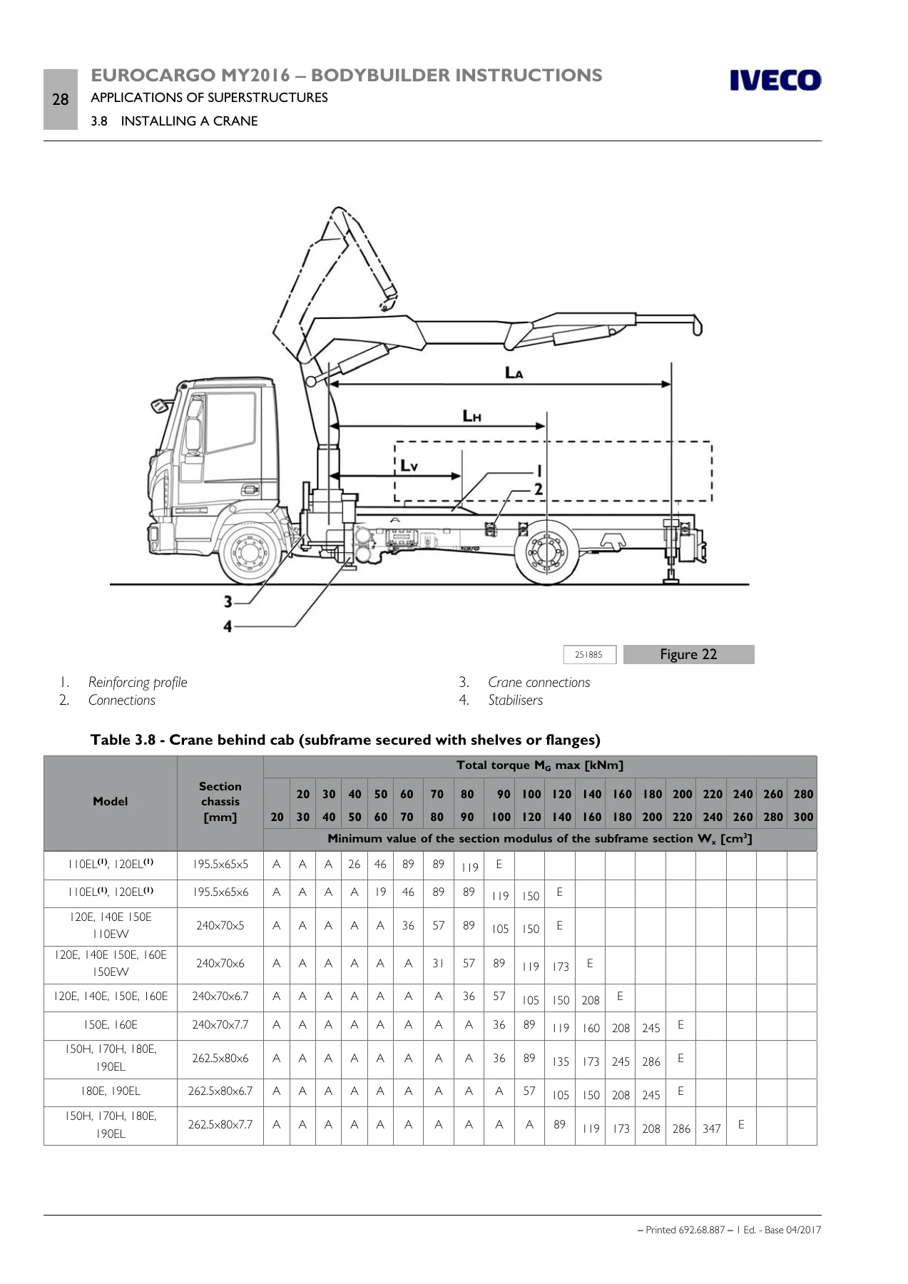
3.8 INSTALLING A CRANEp. 110
Crane behind cabp. 111
Cranes on rear overhangp. 115
Removable cranesp. 117
3.9 INSTALLATION OF TAIL LIFTSp. 117
Base configuration for tail liftsp. 121
VEHH configuration for tail liftsp. 122
3.10 INTERCHANGEABLE OUTFITSp. 123
3.11 CONSTRUCTION OF BOX TRUCK BODIESp. 124
3.12 TILT BEDS (BREAKDOWN RECOVERY)p. 124
3.13 VEHICLES FOR COUNCIL, FIRE SERVICE AND SPECIAL USESp. 125
3.14 FRONT INSTALLATION OF SNOW PLOUGH ATTACHMENTSp. 125
3.15 APPLICATION OF A WINCHp. 125
3.16 CONCRETE MIXER INSTALLATIONp. 126
Section 4 – POWER TAKE-OFFSp. 129
Contentsp. 131
4.1 GENERAL SPECIFICATIONSp. 133
Type of usep. 133
PTO transmissionp. 134
4.2 PTO FROM GEARBOXp. 135
4.3 POWER TAKE-OFF FROM TRANSFER BOXp. 136
4.4 POWER TAKE-OFF FROM DRIVE LINEp. 136
4.5 POWER TAKE-OFF FROM ENGINEp. 137
Torque PTO from the front of the enginep. 137
Torque PTO from the rear of the enginep. 140
Multipower PTO on engine fly-wheelp. 140
4.6 PTO MANAGEMENTp. 141
Principlesp. 142
Definitionsp. 142
Multiplexp. 142
PTO switch (PTOsw x, x = 1, 2, 3)p. 142
Connector 61071p. 142
PTO Mode x (x = 1, 2, 3)p. 142
Physical PTO Activationp. 143
PTO mode 0 (driving mode)p. 143
PTO modes 1, 2, 3 (configurable)p. 143
Changes to the torque curve, maximum rotation speed and steepness of the maximum rotation speed limiterp. 145
4.7 STANDARD CONFIGURATIONSp. 148
Conditions for activating/deactivating PTOp. 148
Intermediate engine speed regulatorp. 150
TIP functionp. 150
Increase/decrease rpm value with SET+/SET-p. 150
Accelerator pedal enabled/disabledp. 150
Allison gearboxp. 150
PTO use with vehicle in motionp. 151
Modifying stored intermediate engine speed value NRESp. 151
Adjusting minimum rpm valuep. 152
4.8 EM (EXPANSION MODULE)p. 152
Section 5 – ELECTRONIC SUB-SYSTEMSp. 155
Contentsp. 157
5.1 ELECTRONIC SYSTEMSp. 159
Position of electronic control unitsp. 160
5.2 BODYBUILDER CONNECTORSp. 164
CONNECTORS IN CABp. 165
CONNECTORS ON CHASSISp. 178
TRAILER CONNECTORSp. 180
5.3 FMS (FLEET MANAGEMENT SYSTEM)p. 182
5.4 CONFIGURATIONS FOR TAIL LIFTSp. 183
Base configurationp. 183
Base configuration with additional ECAS remote control (opt. 4115)p. 185
VEHH configuration (opt. 75182)p. 186
5.5 OPERATOR’S FOOTBOARDp. 188
5.6 ELECTRICAL CIRCUIT MODIFICATIONSp. 190
General informationp. 190
Wiring harness lengthp. 190
Disconnecting electronic control unitsp. 190
Repositioning electronic control unitsp. 191
5.7 ELECTRICAL SYSTEM: OPERATIONSp. 191
General informationp. 191
Precautions for work on the systemp. 191
Precautions for work on the chassisp. 192
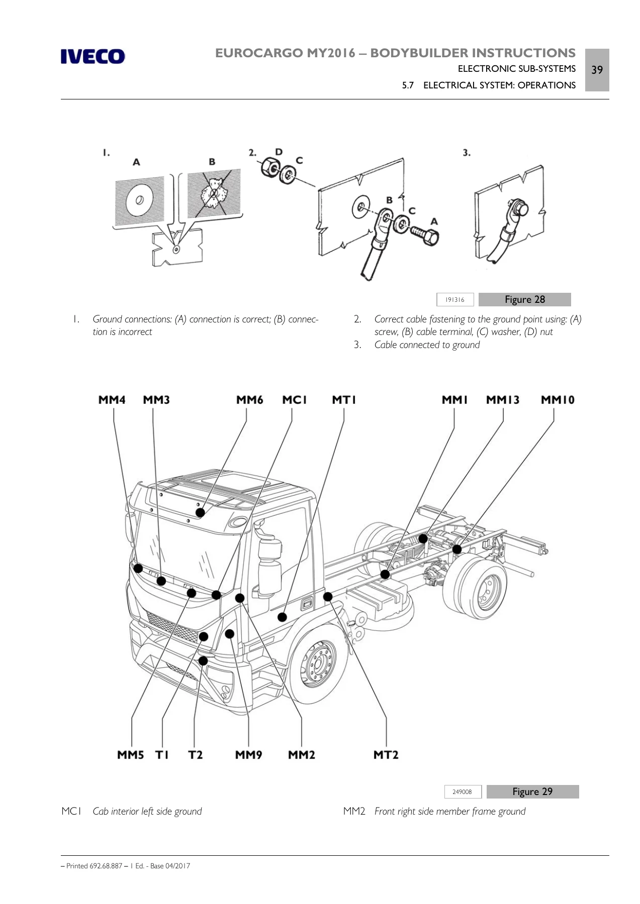
Ground pointsp. 192
Electromagnetic comparabilityp. 195
Reception/transmission systemsp. 197
General instructionsp. 197
Amateur equipment for CB (27 MHz) and 2 m band (144 MHz)p. 198
Equipment for GSM/PCS/UMTS cellular phones and TETRA/TETRAPOLp. 199
GPS reception and satellite navigation equipmentp. 199
5.8 ADDITIONAL EQUIPMENTp. 199
Additional batteriesp. 200
Additional alternatorsp. 201
Additional electrical unitsp. 202
Drawing currentp. 203
Current withdrawal pointsp. 205
a) Connector blockp. 205
b) 21-pin connector 61071 (brown)p. 206
c) Main current switching device (DGC)p. 206
Main current contactor (TGC option)p. 207
Voltage reducerp. 207
Maxifuse and Megafuse fusesp. 207
Voltage reducerp. 208
Additional circuitsp. 208
Precautionsp. 209
Modifying wheelbase and overhangp. 209
Side Marker Lamp installationp. 209
Section 6 – ADBLUE AND SCR SYSTEM (Euro V versions only)p. 213
Contentsp. 215
6.1 GENERAL INFORMATIONp. 217
6.2 THE NITROGEN OXIDE CATALYTIC REDUCTION PRINCIPLEp. 218
Catalytic converterp. 220
AdBlue tankp. 220
6.3 INSTRUCTIONSp. 220
AdBlue tankp. 221
6.4 PIPESp. 221
6.5 POSITIONING THE DOSING MODULEp. 221
AdBlue tank positioned below the supply module (SM)p. 223
AdBlue tank positioned above the supply module (SM)p. 224
Dosing module (DM) positioned below the supply module (SM)p. 224
Dosing module (DM) positioned above the supply module (SM)p. 225
Positioning the dosing modulep. 225
Orienting the dosing module (DM) in the exhaust pipep. 226
Orienting the dosing module (DM) with reference to the rotation angle in the exhaust pipep. 227
Angle of fitting of the exhaust gas pipep. 227
Installing the dosing module in relation to the SCR catalytic converter:p. 227
Exhaust gas pipep. 228
Interventions on the wiring and AdBlue and water pipesp. 229
6.6 WIRING FOR POSITIONING SCR SYSTEM COMPONENTSp. 230
Replacing cables to reposition SCR system componentsp. 230

Why the Bodybuilder Instructions Matter

Conversion work that is not done to the manufacturer’s instructions can affect the structural integrity of the chassis, the braking balance, the stability of the vehicle, and the behaviour of the multiplexed electrical system. It can also invalidate the vehicle’s guarantee and, in the case of safety-related systems such as braking, steering or stability control, require re-approval. Having the correct limits in front of you means the difference between a conversion that passes inspection and one that has to be stripped back and redone. The manual also defines where Iveco authorisation is required before work begins, so the bodybuilder knows in advance which modifications are permitted as standard and which need written approval.

IMAGES PREVIEW

Iveco Eurocargo MY2016 Euro III-V Bodybuilder Instructions Manual 692.68.887 — PDF page 18 preview
Iveco Eurocargo MY2016 Euro III-V Bodybuilder Instructions Manual 692.68.887 — PDF page 112 preview
Iveco Eurocargo MY2016 Euro III-V Bodybuilder Instructions Manual 692.68.887 — PDF page 193 preview

Instant PDF Delivery

The Iveco Eurocargo MY2016 Euro III-V Bodybuilder Instructions is delivered as an instant-download PDF once payment is complete. There is no shipping and no waiting for a physical book. The file can be opened on a workshop PC, laptop, tablet or smartphone, printed for the bench if you prefer paper, and referred to repeatedly through the life of a conversion project. Because it is a digital file, you can search the section you need, print only the pages relevant to a particular job, and keep a copy on every device your team uses.

Whether you are quoting a new body, planning a wheelbase change, sizing a subframe, wiring a tail lift or repositioning an SCR module on a Euro V chassis, this manual provides the approved procedures, the permitted limits and the technical data you need to carry out the work correctly.

Reviews

There are no reviews yet.

Be the first to review “Iveco Eurocargo MY2016 Euro III-V Bodybuilder Instructions Manual 692.68.887”

What Our Customers Say

★★★★★ Live reviews from customers
Loading customer reviews...
0
    0
    Your Cart
    Your cart is emptyReturn to Shop
    🛒
    Recently Purchased
    🕒 verified order