
Demag CC 4800 Electric & Hydraulic Schematics Manual – Serial 41023 PDF
Original price was: $39.95.$24.95Current price is: $24.95.
Complete electric and hydraulic schematics set for the Demag CC 4800 crawler crane, serial 41023. Includes winch drum layout, boom electrics, luffing fly jib electrics, SLI DS 350 troubleshooting manual, wiring diagrams, pressure and force transducer data, and error-code diagnostics.
Description
Demag CC 4800 Electric & Hydraulic Schematics – Serial 41023
This PDF brings together the electric and hydraulic schematics package issued for the Demag CC 4800 crawler crane under serial number 41023. It covers the superstructure and carrier electrical system, the boom and luffing fly jib electrical circuits, the hydraulic pump and control layout, and the PAT DS 350 load moment indicating system with its full troubleshooting documentation. The schematics are presented as full-page drawings with component legends, terminal references, and cross-references to the machine’s control console.
File Details
- Manual type: Electric and hydraulic schematics / wiring diagrams with SLI troubleshooting manual
- Brand: Demag (Mannesmann Demag Baumaschinen)
- Model: CC 4800
- Serial number: 41023
- Document identifier: Ident-Nr. 3.18.200.40, 3.7.125.3.40
- Language: English (with German legend entries on some schematic title blocks)
- File format: PDF
- Pages: 209
Chapters and Sections Covered
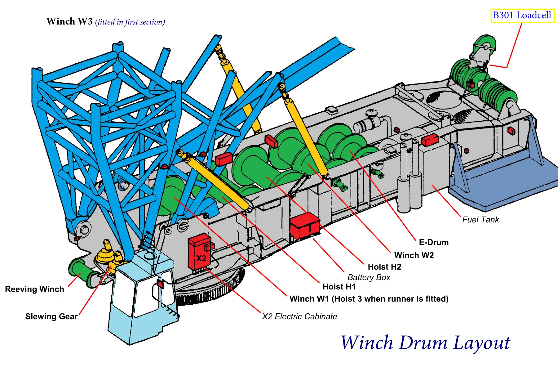
- Winch Drum Layout – W1 (Hoist 3 when runner fitted), W2, W3, Hoist H1, Hoist H2, E-Drum, B301 Loadcell, reeving winch, slewing gear, fuel tank, battery box, X2 electric cabinet
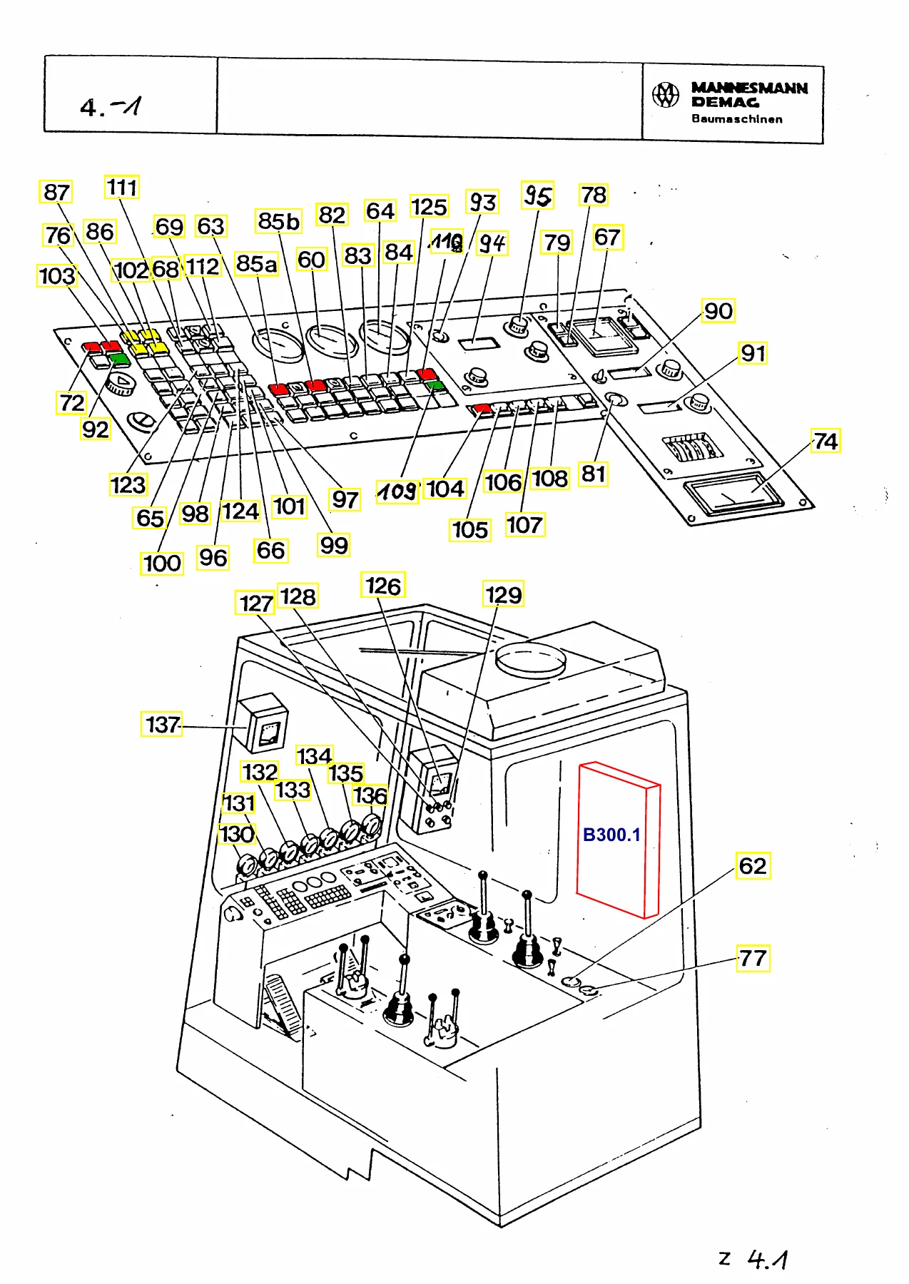
- Operator Console Layout – control levers, push-buttons, key-operated switches, selector switches, gauges and indicator lamps with numbered references
- Control Functions Table – item-by-item description of every lever, switch, push-button, pedal, gauge and indicator lamp on the console
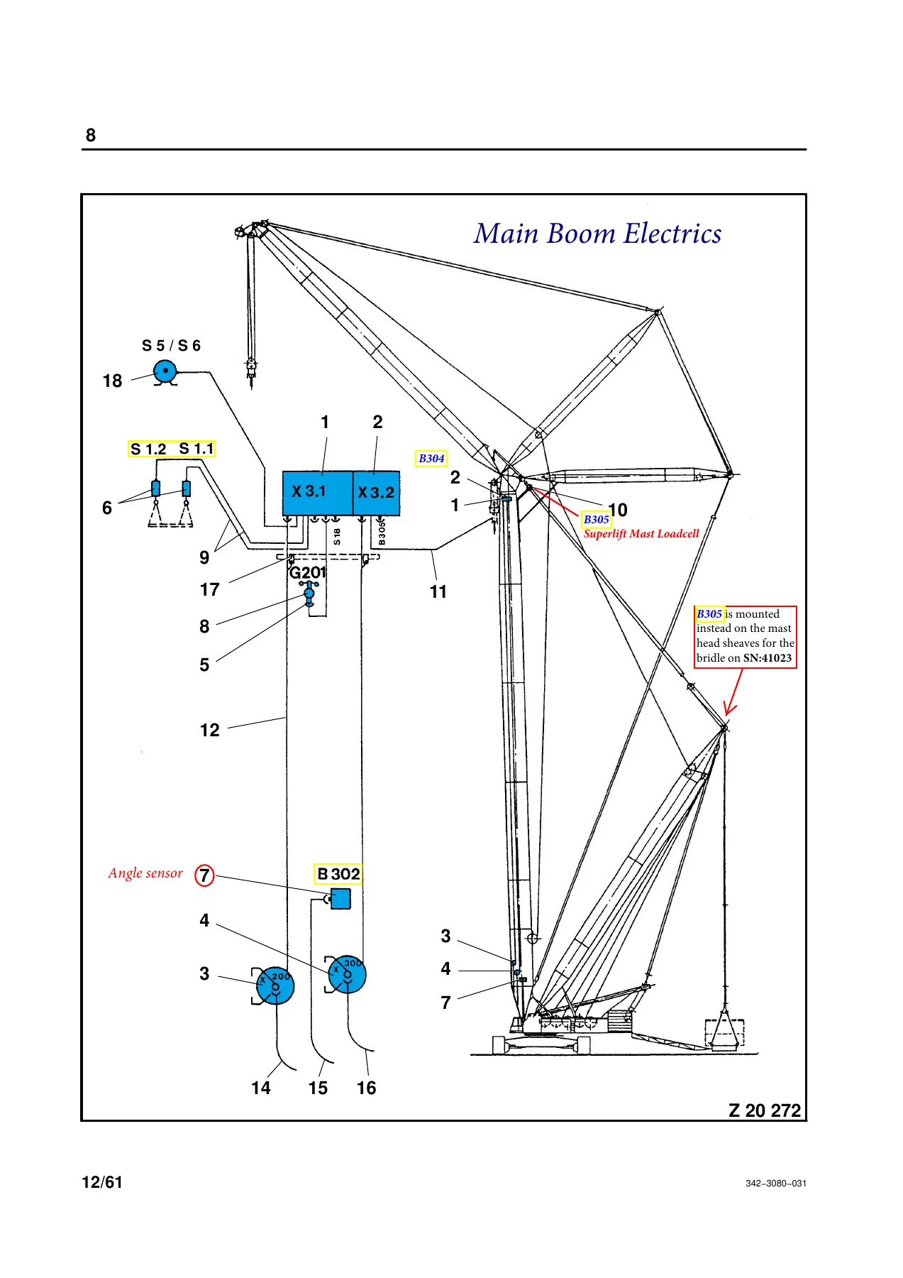
- Main Boom Electrics – boom distributor box, boom distributor box load limit device, cable drums, anemometer line, hoist limit switch, angle transmitter, load cell, balance indicator
- Luffing Fly Jib Electrics – universal boom point junction box, cable drums, load cell, angle transducer, limit switch on back stroke cylinder, hoist limit switch
- Superstructure Electrics – main fuse, terminal rails, batteries, alternator, relay assignments, ignition switch, engine start and stop circuits
- Temperature, Oil Pressure and Coolant Monitoring – sensor and switch wiring for coolant temperature, engine oil pressure, fuel gauge, hydraulic oil temperature, air filter control, coolant level control
- Lighting and Cab Circuits – horn, cab light, Rotafare light, superstructure outside light, cab outside lights, instrument dash lighting
- Wiper and Auxiliary Circuits – windscreen wiper motors, temperature switch, solenoid valves, socket outlets
- Hoist Limit and Lower Limit Switch Circuits – override circuits, lowering cut-off at three wraps remaining, winch shutdown logic chart
- Switch-Over and High Range Circuits – E / W3, W2 control lever selection, H1 / H2 selection, high range and hydraulic motor trimot control
- Brake, Travel and Counterweight Wagon Circuits – slew brake, travel brake, wagon lockout, flow control, slewing with counterweight wagon against increased resistance
- Support, Outrigger and Counterweight Wagon Pressure Circuits – ground clearance indication, pressure rating mast support, backstop cylinders
- Low Voltage and High Voltage Warning – wind speed indicator, high voltage warning system, auxiliary console EI 31
- Heating and Air Conditioning – circulating pump, control unit, fuel preheater for hot water heater, air conditioning unit, condenser and evaporator fans
- Diesel Heater System – burner, glow plug, dosing pump, control unit, safety thermostat wiring
- Electric Drive System – electric motor start and stop, thermal protection, direction of rotation, standstill heating, slip ring body heating, control cabinet heating
- SLI Type DS 350 Troubleshooting Manual – operating mode switch setting, hierarchy of error messages, and full error code table
- Error Code Reference – E01 to E97 codes with cause and elimination for radius, angle, length, pressure, force, EPROM, RAM, relay and data transmission faults
- Input Channel Documentation – channel #1 length main boom, #2 pressure piston side, #3 pressure rod side, #4 force transducer, #5 angle sensor main boom, #6 angle sensor jib boom, #7 length sensor 2
- CPU Type DS 350 KD – mother board, power supply PCB, extension boards 014, 023, 052 and 060, terminal blocks and measuring points
- Transducers and Hoist Limit Switches – pressure transducer DAVS, rope tensiometer load cell KMD, angle transducer WG 103 / WG 203 / WG 407, length/angle transducer LWG 204 / 208 / 221
- Load Cell Types and Identification – KM1, KM2, KM3, ZM1 load cell assignments for LH, SH, LW, SW, LSL, SSL and SWSL configurations
- Location of Components on Lattice Boom Cranes – central unit, operating/display console, force transducer, angle transducer positions
- Hydraulic Pump Layout – P1, P2, P3, P4.1, P4.2, P4.3, P5.1, P5.2, P5.3 pump construction, maximum pressure and capacity
Working through this material gives the technician a complete map of the CC 4800’s electrical architecture: from the main battery isolator and terminal rails in the superstructure, through the boom and fly jib distributor boxes, all the way to the transducers feeding the load moment indicating computer. The schematics are drawn with numbered current paths, and the accompanying tables translate every device designation (F, H, K, M, S, X, Y, R, G, B, P) into its location and function. That combination is what makes a fault-finding job on this crane practical rather than guesswork.
What This Schematics Package Enables
With the wiring and hydraulic diagrams in hand, a technician can trace a fault from the console indicator lamp back through the relay, terminal rail and cable to the sensor at the boom head. The SLI DS 350 section takes this further by pairing each error code with its likely cause and the corrective action, whether that means replacing a relay, checking a connector for water ingress, resetting a pressure channel or replacing the main board. Because the machine’s own crane definition switch and operating mode switch feed directly into the SLI, the document also explains why an incorrectly selected operating mode produces an E04 code and how to acknowledge it.
The hydraulic side identifies which pump serves which working circuit, together with the pressure rating of each pump group. For a crane of this size, where several winches and the derricking gear share a common pump assembly, knowing which pump feeds circuit 1, 2, 3 or the pilot pressure line is essential before opening a hydraulic connection.
Why This Matters for CC 4800 Owners and Service Teams
The CC 4800 is a heavy lattice boom crawler crane with Superlift and luffing fly jib configurations, and its electrical system reflects that complexity. Relay numbering, terminal designations and switch-over logic are specific to the machine, and generic electrical knowledge will not replace the actual circuit drawings. Having the correct schematic for serial 41023 removes the risk of working from a diagram that belongs to a different build or a different serial number.
For anyone maintaining, repairing or diagnosing a CC 4800, these schematics turn an opaque fault into a sequence of measurable test points. The SLI documentation in particular supports the load moment system that protects the crane from overload, so understanding its error codes is directly tied to safe operation.
IMAGES PREVIEW
Instant PDF Delivery
The file is delivered as a PDF immediately after purchase, with no shipping and no waiting. It can be opened on a laptop, tablet or phone at the machine, and pages can be printed for use in the cab or workshop. Whether you are tracing a single lamp circuit or rebuilding the entire SLI input chain, the document stays usable in the environment where the work actually happens.



Reviews
There are no reviews yet.