
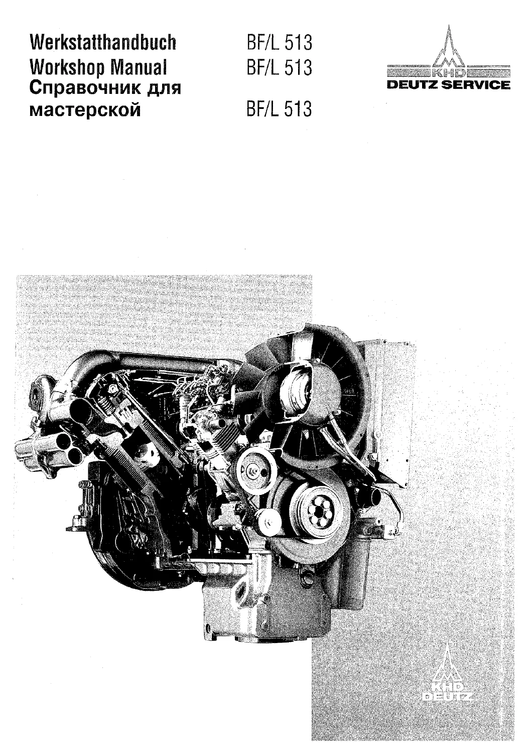
Deutz BF/L 513 Workshop Manual 0297 5962 PDF – F8L F10L F12L BF8L BF10L BF12L
Original price was: $38.95.$22.95Current price is: $22.95.
Trilingual Deutz Service workshop manual 0297 5962 for air-cooled B/FL 513 diesels: specification tables, checking and adjusting, component repair, complete engine strip-down and rebuild, KKK K1/K2 turbocharger work, and special tools for F8L, F10L, F12L, BF8L, BF10L and BF12L 513 engines.
Description
File Details
- Manual type: Workshop Manual / Werkstatthandbuch / Справочник для мастерской
- Brand / series: Deutz Service (KHD Deutz) B/FL 513 air-cooled diesel engines
- Document number: 0297 5962
- Languages: German, English and Russian
- Page count: 488
- File format: PDF
The Deutz BF/L 513 Workshop Manual 0297 5962 PDF – F8L F10L F12L BF8L BF10L BF12L is the Deutz Service shop book written for qualified personnel who repair and set up the B/FL 513 engine family. The cover and section titles use BF/L 513 and B/FL 513; the specification tables name six production variants. Operation and routine servicing stay in the separate Operation Manual, and parts orders follow the matching spare-parts list. This workshop book is not on a running change service, so later Technical Circulars still apply when a job is done.
Engines Covered in the Specification Tables
Section 1 prints side-by-side data for naturally aspirated F engines and turbocharged BF engines, including long-stroke L and intercooled LC/C options:
- F8L 513 / F8L 513 L — 8-cylinder four-stroke diesel, swept volume 13382 cm³ (L = 14412 cm³)
- F10L 513 — 10-cylinder, 16728 cm³
- F12L 513 — 12-cylinder, 20074 cm³
- BF8L 513 / BF8L 513 LC — turbocharged 8-cylinder, 12763 cm³ (LC = 13744 cm³)
- BF10L 513 — turbocharged 10-cylinder, 15953 cm³
- BF12L 513 / BF12L 513 C — turbocharged 12-cylinder, 19144 cm³
All six are direct-injection four-stroke diesels. Bore is 128 mm on the F range and 125 mm on the BF range. Stroke is 130 mm, rising to 140 mm on the L/LC long-stroke builds. Rated speed is 2300 rpm (2150 rpm on F L engines, 2100 rpm on BF L/LC engines). Minimum idle is 600 rpm. Rotation is counter-clockwise when facing the flywheel. Approximate dry weights without starter and generator run from about 835 kg on the F8L 513 to about 1250 kg on the BF12L 513, with higher DIN 70020-A figures when starter, alternator and a front- or parallel-mounted intercooler are fitted. Compression ratio is 16.7 (18.5 on L) for the naturally aspirated engines and 15.8 (17.0 on LC) for the turbocharged group. Compression-pressure windows are 22–30 bar, or 25–35 bar on L/LC. Firing orders are given for 8-, 10- and 12-cylinder layouts. Overall length, width and height with a standard flywheel are tabulated per model, including the extra length and height of a front-mounted intercooler on BF8L 513 LC.
IMAGES PREVIEW
Chapters Covered
- 1. Specification data — general engine data and weights; fuel injection system (Bosch pump, governor, nozzle, commencement of fuel delivery, advance/retard unit); cylinder unit (cylinder head, valve guide, valve seat insert, valve, valve spring, valve clearance, distances to be checked, cylinder head studs); cylinder; piston and piston rings; motion parts (crankshaft, crankpins, main bearing journals, thrust bearing journal, main bearings and bores); connecting rod; camshaft and valve timing; lubrication system (lube oil pump and oil pressure); tightening specifications
- 2. Checking and adjusting — valve clearance; compression pressure; top dead centre; commencement of fuel delivery; injector; exhaust thermostat; electro-hydraulic cooling fan control EHG and EHGK; crankcase breather valve; fuel injection pump
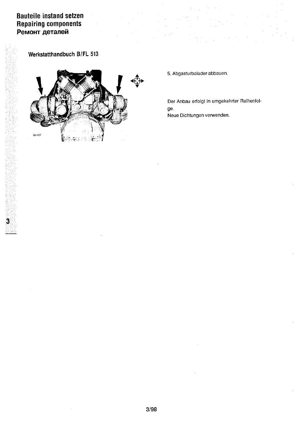
- 3. Repairing components — cylinder head; cylinder; piston; connecting rod; rocker arm bracket; pushrods, cover tubes and tappets; lube oil pump and pressure relief valve; crankcase; camshaft bearing bushes; refacing the cylinder seating on the crankcase; replacing the main oil pipe; crankshaft; camshaft; flywheel; advance/retard unit (standard and P-type injection pump); bush and shaft seal in the advance/retard bearing race; injector; hydraulic cooling fan (standard and with fan brake); fan drive gearing; torque limiter; crankshaft seals at flywheel end and auxiliaries carrier without stripping the engine; removing and refitting the exhaust turbocharger; removing and refitting the air compressor
- 4. Disassembly and reassembly of the complete engine — full strip (pages 4/1–4/24) then staged rebuild: tappet bridge and piston cooling nozzles with jet-pattern check; oil pipe; tappets; camshaft; crankshaft bearings; pistons, connecting rods and cylinders; cylinder unit and motion parts; adapter housing, rear cover and shaft seal; flywheel; piston-crown clearance measurement; cylinder heads; lube oil pump and scavenge pump; auxiliaries carrier, oil-filter bracket, oil pan and starter; pinion shaft; injection-pump bracket and advance/retard unit; cooling-fan drive, air baffles and rails; pressure-regulating valve; pushrod tubes, pushrods and rocker brackets; injectors; dipstick tube, vibration damper and vee-belt pulley; cooling fan; valve piston or thermostat; engine oil cooler, fan oil line and crankcase breather; cylinder-head monitoring gauge points; injection pump; solenoid valve, shutdown linkage, fuel lines and overflow valve; injection lines, wiring looms and temperature regulator; cover plates, transverse oil cooler and oil filter; intake and exhaust manifolds; generator, vee-belts and tachometer drive
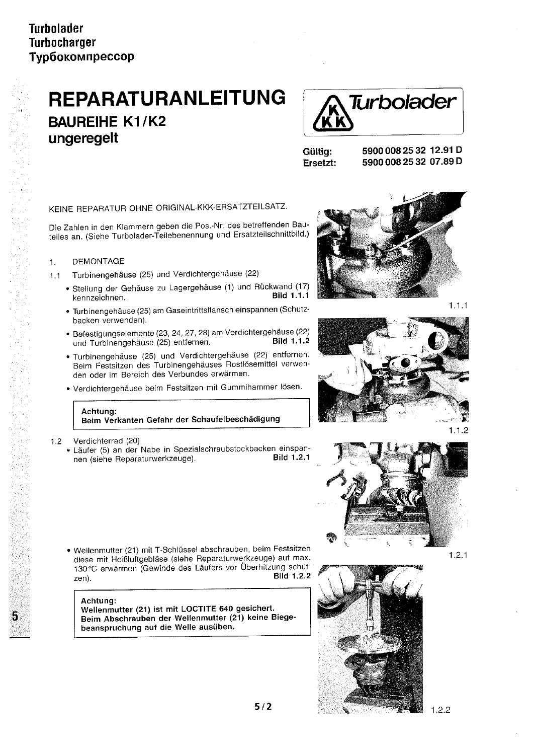
- 5. Turbocharger — KKK unregulated K1/K2 series maintenance, repair and spare-parts documentation (document 5900 008 25 32, valid 12.91, superseding 07.89), covering turbine and compressor housing removal, compressor wheel, rotor work, Loctite 640 shaft-nut practice, torque and axial/radial clearance tables for sizes K14/K16 through K29
- 6. Tools — numbered special tools, including assembly stand 6066 for clamping air-cooled engines on both sides, extra angle plates 6066/151, and compression-tester adapter 100 060
Taken together, the six sections give a technician the wear limits, tightening angles, setting values and illustrated sequences needed to diagnose, overhaul and rebuild a B/FL 513 engine on the stand rather than guessing from a parts book. Pictograms next to the short German, English and Russian texts mark disassembly, reassembly, oiling, marking, special tools and safety points so the same job can be followed in any of the three languages.
Injection Equipment and Service Settings
The Deutz BF/L 513 Workshop Manual 0297 5962 PDF – F8L F10L F12L BF8L BF10L BF12L lists Bosch MW or P injection pumps according to engine, with MW used on the base F8L 513 and BF8L 513 and P pumps on the remaining variants and on the L/LC options. Governors are Bosch RQV, RQ/RQV or type 1042. Minimum transfer pressure after about five crankshaft revolutions is 300 bar. Relief-valve tightness is checked at 150 bar, with a drop to 140 bar in one minute permitted. Injector nozzles are Bosch DLLA 145 S 1023 on the F family (DLLA 145 S 1218 on L) and Bosch DLLA 148 S 885 on the BF family (DLLA 145 S 1218 on LC). Re-use opening pressures are 235 +8 bar (F and L) or 270 +8 bar (BF), with new-setting values 240 +8 and 275 +8 bar. Static and dynamic commencement of fuel delivery, with and without the advance/retard unit, are referred to the engine rating plate. Advance range is 7° crank angle (8° on L/LC), starting at 1200 rpm (1400 rpm on L/LC) and ending at 2500 rpm (2100 rpm on L/LC).
Cold valve clearances in the data tables are 0.2 mm inlet and 0.3 mm exhaust. After cylinder-unit repairs the book specifies 0.3 mm inlet and 0.4 mm exhaust, then a return to the standard figures after 50 running hours. The checking chapter insists on a cold engine that has stood at ambient temperature for at least seven hours. If that wait is impossible, a warm-engine method is given: cool 2.5 hours after shutdown, set 0.3 / 0.4 mm, and finish the job within three hours of shutdown. Valve recess targets are EV 3.25 ± 0.4 mm and AV 3.0 ± 0.4 mm. Valve timing with 0.2 mm clearance is inlet opens 22° before TDC, inlet closes 52° after BDC, exhaust opens 67° before BDC, exhaust closes 27° after TDC. Inlet cam lift is 8.75 mm on F engines and 8.5 mm on BF engines; exhaust cam lift is 9.0 mm.
Lubrication, Fasteners and Wear Limits
The lube-oil pump runs at 3020/2300 relative to engine speed. Delivery at 5 bar and 90 °C with SAE 30 oil is 8600 l/h on F8L 513, 9700 l/h on F10L 513, BF8L 513 and BF10L 513, and 11900 l/h on the 12-cylinder engines. Delivery-gear width is 46 mm on F8L 513 and 52 mm on the others. Axial gear clearance is 0.040–0.085 mm (wear limit 0.12 mm); backlash to the crankshaft gear is 0.15–0.25 mm. Pressure-regulating valve setting is 4.5–6.0 bar. Minimum oil pressure at low idle is 0.5 bar. Safety valve on the oil pump is 8.0–11.0 bar. Cooler by-pass is 1.5 bar where no oil-cooler thermostat is fitted.
Tightening tables use an initial torque plus angle steps. Examples printed in the book include vertical main-bearing bolts at 50 + 10 Nm then 30° + 60° + 60° (150° total), big-end bolts at 50–60 Nm plus 60° + 60°, flywheel bolts at 40 Nm plus 30° + 60° + 60°, and cylinder-head studs at 60 Nm plus 180° total on FL 513 or 210° total on BFL 513 heads of RR 350 material. Injector clamp is 40 Nm; injector cap nut 60–80 Nm; cooling-fan grooved nut 300 ± 30 Nm after a 50 Nm pre-torque. Order of tightening is called out where it matters.
Shop Jobs the Procedures Actually Walk Through
Chapter 2 is the day-to-day setting chapter: overlap-based valve adjustment with cranking gear 100 300 or mandrel 190 200, compression testing with tester 2461 and adapter 100 060 after a short mid-speed run to wet the rings, TDC finding, static fuel-delivery timing with high-pressure hand pump 101 500, injector opening-pressure checks on ISO 4113 test oil (with a warning to keep hands out of the spray), exhaust-thermostat strip and set, EHG / EHGK electro-hydraulic cooling-fan emergency switching, and crankcase-breather testing on a hot engine at high no-load fan speed against a +10 to −50 mm water-column window.
Chapter 3 is the component rebuild chapter. Cylinder-head work includes valve-guide and seat-insert dimensions, lathe recutting of seats and measuring valve recess to the head face. Pistons carry the diameter on the crown; rings come off with pliers 130 300 and trapezoid-groove wear is checked with gauge 130 380. Connecting rods, rocker brackets, pushrods and tappets, the oil pump and relief valve, crankcase repairs, camshaft bushes, and machining of the cylinder seating on the crankcase are all sequenced. Flywheel ring gears are marked at a recessed tooth and heated to 220 °C before fitting so the marks line up. Advance/retard units for both standard and P-pumps are dismantled, and the bush plus shaft seal in the bearing race can be renewed on their own. Hydraulic cooling fans — standard and braked — plus the two-wheel fan drive and torque limiter have long illustrated overhauls. Viton crankshaft seals can be pulled at the flywheel end or auxiliaries carrier with tool 142 750 without taking the engine apart. Turbocharger and air-compressor R&R close the chapter, always with new seals on refit.
Chapter 4 is the full-engine path: drain and strip accessories, oil cooler and baffles, fuel and shutdown linkage, then the short block; rebuild starts at the tappet bridge and piston-cooling nozzles (including a spray-pattern check), works through crankshaft bedding, piston-to-head clearance, head alignment to manifold flanges, pumps, carrier, injection pump and fan, and finishes with belts that must be retensioned after a short first run. Chapter 5 adds the KKK K1/K2 turbo overhaul, which forbids repair without an original KKK parts kit and gives housing orientation marks, maximum 130 °C heat on a Loctite-locked shaft nut, and clearance limits such as 0.10 mm axial on K14/K16 and 0.16 mm on the larger frames. Chapter 6 catalogues the stands, pullers, gauges and adapters called out in the earlier jobs.
How the Trilingual Layout Works in the Shop
Most procedure spreads put German on the illustrated page and English plus Russian on the facing text page, or run all three in stacked blocks on specification sheets. A symbol key at the front explains disassembly, reassembly, obstructing-part removal, torque/dimension checks, special tools, installation direction, visual inspection, parts that must be renewed, locking and sealing, personal-injury and part-damage warnings, oiling and greasing, marking before strip-down, filling and draining, and references back to numbered specification lines (for example line 121). The foreword states that repairs must match the equipment manufacturer’s intended use and that only Deutz Service International GmbH parts released for that use should go into conversions. Springs, snap rings and similar parts are flagged as injury hazards if mishandled. Accident-prevention rules and the need for complete, serviceable special tools are spelled out before any wrench turns.
Use This Manual on the Stand
With the Deutz BF/L 513 Workshop Manual 0297 5962 PDF – F8L F10L F12L BF8L BF10L BF12L on the bench, a technician can set valves and injection timing, measure compression, overhaul heads, pistons, rods, crankshaft and camshaft, renew seals in situ, rebuild the hydraulic cooling fan and advance unit, strip and rebuild the complete air-cooled engine, and service the KKK K1/K2 turbocharger to the printed clearances and torques. Those figures and sequences are what keep a 513-series diesel from leaving the shop with the wrong injector opening pressure, the wrong head-bolt angle or a cooling fan nut that was never taken to 300 Nm. Download the PDF after payment, open it on any device, and print the pages you need for the job in front of you — no shipping wait and no guesswork from a general catalogue.
Reviews
There are no reviews yet.