
DEUTZ TCD 2013 2V Workshop Manual 0312 2916 – 2010 PDF
Original price was: $49.95.$29.95Current price is: $29.95.
Comprehensive 471-page DEUTZ TCD 2013 2V workshop manual covering TCD 2013 L4 2V and L6 2V engine repair, inspection, adjustment and component replacement procedures. Includes testing and setting data, tightening specifications, illustrated job cards, Common Rail fuel-system work, cylinder head and valve service, crankshaft and piston procedures, cooling and lubrication systems, turbocharger work, electrical components, standard tools and special tools.
Description
DEUTZ TCD 2013 2V Workshop Manual 0312 2916 – 2010 PDF
The DEUTZ TCD 2013 2V Workshop Manual 0312 2916 – 2010 PDF is a detailed workshop reference for maintenance and repair work on the TCD 2013 2V engine family. The technical data identifies both TCD 2013 L4 2V and TCD 2013 L6 2V configurations, while the repair section provides illustrated job cards for engine disassembly, inspection, adjustment, component renewal and reassembly. This is a competence level 3 workshop manual intended for work that requires appropriate technical knowledge, workshop equipment and, for a number of operations, specified special tools.
The manual combines service data with step-by-step procedures rather than presenting repair instructions in isolation. Testing and setting values, tightening specifications, safety requirements, tool references and linked job-card numbers are integrated into the repair workflow. The document also explains that DEUTZ engines may be equipped differently according to their installation, so not every component described will necessarily be fitted to every individual engine.
File Details
- Manual type: Workshop Manual, competence level 3
- Brand: DEUTZ
- Model: TCD 2013 2V
- Engine configurations identified: TCD 2013 L4 2V and TCD 2013 L6 2V
- Language: English
- Page count: 471 pages
- File format: PDF
- Order number: 0312 2916 en
- Edition: 1st Edition
- Date: 02/2010
Repair Procedures and Workshop Job Cards
A major part of this DEUTZ TCD 2013 2V workshop manual is arranged as illustrated job cards. Each procedure identifies the engine type, job-card number, tools and related procedures, followed by the work sequence with photographs or diagrams. Where applicable, the instructions include tightening values, installation positions, replacement requirements, measuring points and cautions that matter during reassembly.
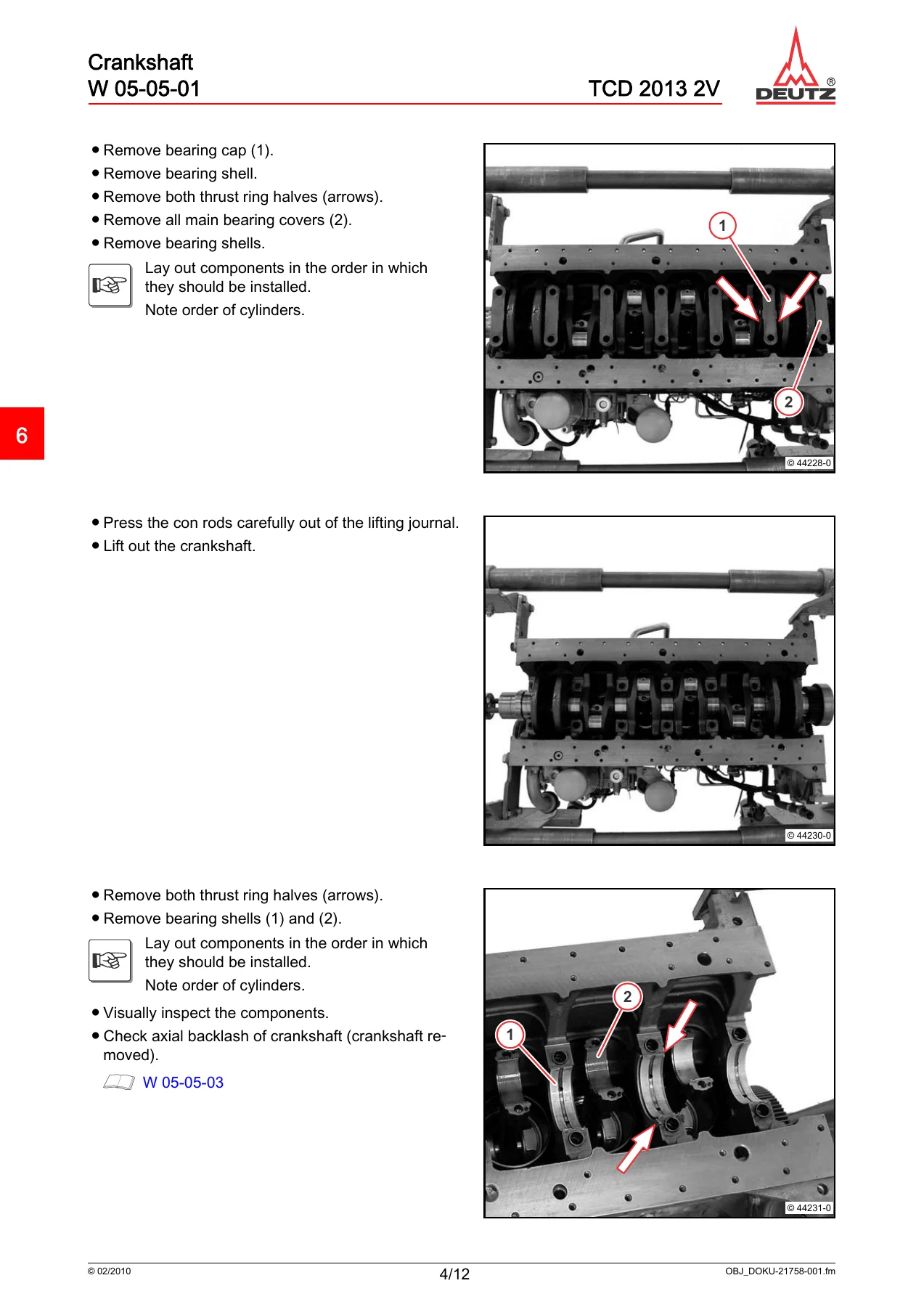
The engine mechanical coverage is extensive. Procedures include removal and installation of the crankshaft, checks of main bearing pins and lifting journals, crankshaft run-out and axial clearance, flywheel work, torsional vibration damper service and crankshaft sealing-ring replacement on both sides. Piston and connecting-rod work includes removal and installation, piston inspection, piston-ring and groove checks, small-end and big-end measurements, connecting-rod alignment checks and bearing-clearance assessment.
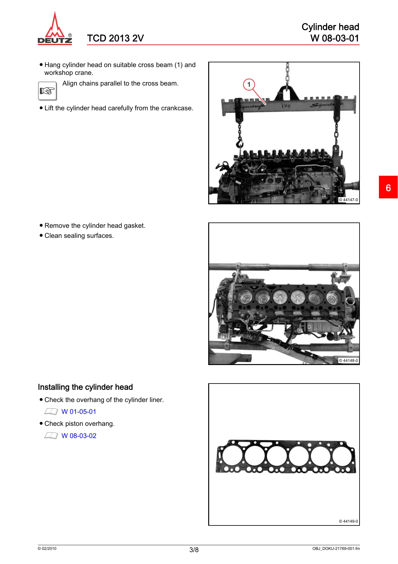
Cylinder and cylinder-head work is similarly detailed. The manual covers removal, installation and testing of cylinder liners; liner collar contact and overhang measurements; piston overhang measurement; cylinder-head removal and installation; cylinder-head gasket selection according to measured piston projection; valve removal and installation; valve dimensions; valve-guide clearance; valve lag; rocker arms; and valve-clearance adjustment. Compression-pressure testing is also documented, including the method for comparing cylinders.
Fuel System, Common Rail and Air Handling
The DEUTZ TCD 2013 2V Workshop Manual 0312 2916 – 2010 PDF contains dedicated Common Rail safety and cleanliness instructions before the repair job cards begin. It stresses protection of the high-pressure fuel system from contamination, immediate closing of open connections, clean work areas and appropriate precautions before working on pressurized fuel components.
Fuel-system job cards cover the control block, high-pressure pump, injector, fuel filter console, fuel supply pump, rail, pressure-limiting valve and rail-pressure sensor. Related procedures also address fuel lines and sensors. High-pressure pump work includes separate job cards for installation positions A and B. The manual repeatedly identifies required waiting time after engine shutdown before fuel-system work and gives assembly instructions, tightening procedures and tool references for these components.
Air and exhaust-side work includes the charge-air line, pressure/temperature sensor, exhaust line, turbocharger, exhaust return module and its solenoid valve. Procedures are illustrated so component positions, fasteners, connectors and installation details can be followed alongside the written sequence.
Lubrication, Cooling, Belt Drive and Electrical Components
Lubrication-system procedures include the lubricating oil pan, oil suction pipe, lubricating oil cooler, cooler housing, crankcase bleeding and associated components. The job cards show sealing-surface preparation, gasket or sealing-ring replacement where specified, use of packing compounds, tightening sequences and component installation positions.
Cooling and drive-system coverage includes the coolant pump, thermostat, thermostat housing, V-belt and V-belt pulley, V-rib belt tensioner, fan drive and fan console. The manual includes belt-tension checking procedures and states that the tension of a new V-belt is to be checked after it has run for 15 minutes under load. Technical data also provides setting information for the coolant thermostat and belt tension.
Electrical and starting-system job cards cover the starter, generator, cable harness, crankshaft and camshaft impulse transmitters, coolant temperature transmitter, oil-pressure switch, fuel-pressure sensor, charge-air pressure/temperature sensor, heating flange and glow plugs. These procedures are linked to the mechanical repair sequence where removal of electrical components is necessary for access.
Testing, Measurement and Tightening Data
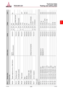
The technical-data section is especially useful during inspection and assembly because it consolidates testing and setting values for the TCD 2013 2V. It includes dimensional data for valves, valve guides, valve seats, valve springs, rocker arms, crankshaft journals and bearings, connecting rods, piston pins, pistons, piston rings, cylinder liners and the camshaft. The manual also identifies the different ignition sequences for the four-cylinder and six-cylinder configurations.
Examples of workshop measurements documented in the manual include cylinder bore and liner dimensions, piston diameters at defined measuring heights, piston-ring joint clearances, crankshaft journal diameters, crankshaft axial clearance, connecting-rod bearing clearance, valve-stem clearance and valve dimensions. Procedures show where and how measurements are to be made rather than providing values without context.
The tightening-specification section covers engine mounting, cylinder head, rocker-arm supports, crankcase and bearing components, gearcase, turbocharger, Common Rail components, oil cooler, cooling-system parts, flywheel, belt drive, starter, generator, sensors and numerous pipe connections. Multi-stage tightening sequences and rotation-angle tightening are shown where required. The individual repair job cards repeat relevant values at the point of use so the mechanic can follow the procedure and the associated specification together.
Chapters Covered
- 1 Foreword
- 2 General
- 3 User notes
- 3.1 General
- 3.2 Specifications
- 3.3 Operating manual and workshop manual
- 3.4 Job cards
- 3.5 Explanation of symbols
- 4 Technical data
- 4.1 Testing and setting data
- 4.2 Tightening specifications
- 5 Job card overview
- 5.1 Sorted alphabetically
- 5.2 Sorted numerically
- 6 Job cards
- Crankcase and front cover
- Lubricating oil sump
- Cylinder liner
- V-belt pulley add-on and torsional vibration damper
- Flywheel and crankshaft
- Connecting rod and piston
- Cylinder head, valves and compression-pressure testing
- Gearcase
- Camshaft
- Control parts, valve clearance and rocker arms
- Lubricating oil cooler and oil suction pipe
- High-pressure pump and control block
- Injector, fuel filter, fuel pump, rail and fuel pipes
- Charge-air line
- Coolant pump and thermostat housing
- Fan drive, belt tensioner and fan console
- Exhaust line and turbocharger
- Generator and starter
- Engine mounting and connection housing
- Cable harness, transmitters, switches and sensors
- Turning gear
- Heating flange and glow plugs
- 7 Commercial tools
- 8 Special tools
Taken together, these sections give a technician a connected repair path from preparation and safety through dismantling, inspection and measurement to assembly and final adjustment. Cross-references between job cards are particularly useful for larger repairs in which several components have to be removed before the target part can be accessed.
Standard and Special Tool References
The manual contains dedicated tool sections rather than leaving tool requirements implicit. Commercial tools include items such as the V-belt tension measuring device, rotation-angle disc, Torx tool set, valve-clearance screwdriver inserts, open-end wrench adapter, pricker, assembly lever and spring-band pliers. Special-tool pages identify dedicated equipment for compression-pressure testing, engine turning, precision measurement, high-pressure line work, injector removal, glow-plug work, cylinder-head support, piston-ring service, crankshaft seal installation, cylinder-liner removal and installation, sealing the fuel system, engine mounting and Common Rail testing.
This tool information is useful when planning a repair because each job card can be checked against the equipment needed before dismantling begins. Tool numbers and illustrations help distinguish dedicated fixtures and measuring equipment from ordinary workshop tools.
For Engine Repair, Measurement and Reassembly
The DEUTZ TCD 2013 2V Workshop Manual 0312 2916 – 2010 PDF supports substantial workshop work on the TCD 2013 L4 2V and L6 2V configurations, from cylinder-head, piston, liner, crankshaft and camshaft procedures to Common Rail fuel-system, turbocharger, lubrication, cooling, belt-drive, sensor and starting-system repairs. Its value during these jobs comes from having the work sequence, inspection points, tool references, setting data and tightening specifications available together, helping technicians carry out assembly and adjustment according to the documented procedure instead of relying on memory or approximate settings.
After purchase, the manual is supplied as an instant PDF download, so there is no physical book and no shipping delay. The PDF can be opened on compatible phones, tablets and computers and pages can be printed when a paper workshop reference is more convenient.
Reviews
There are no reviews yet.