
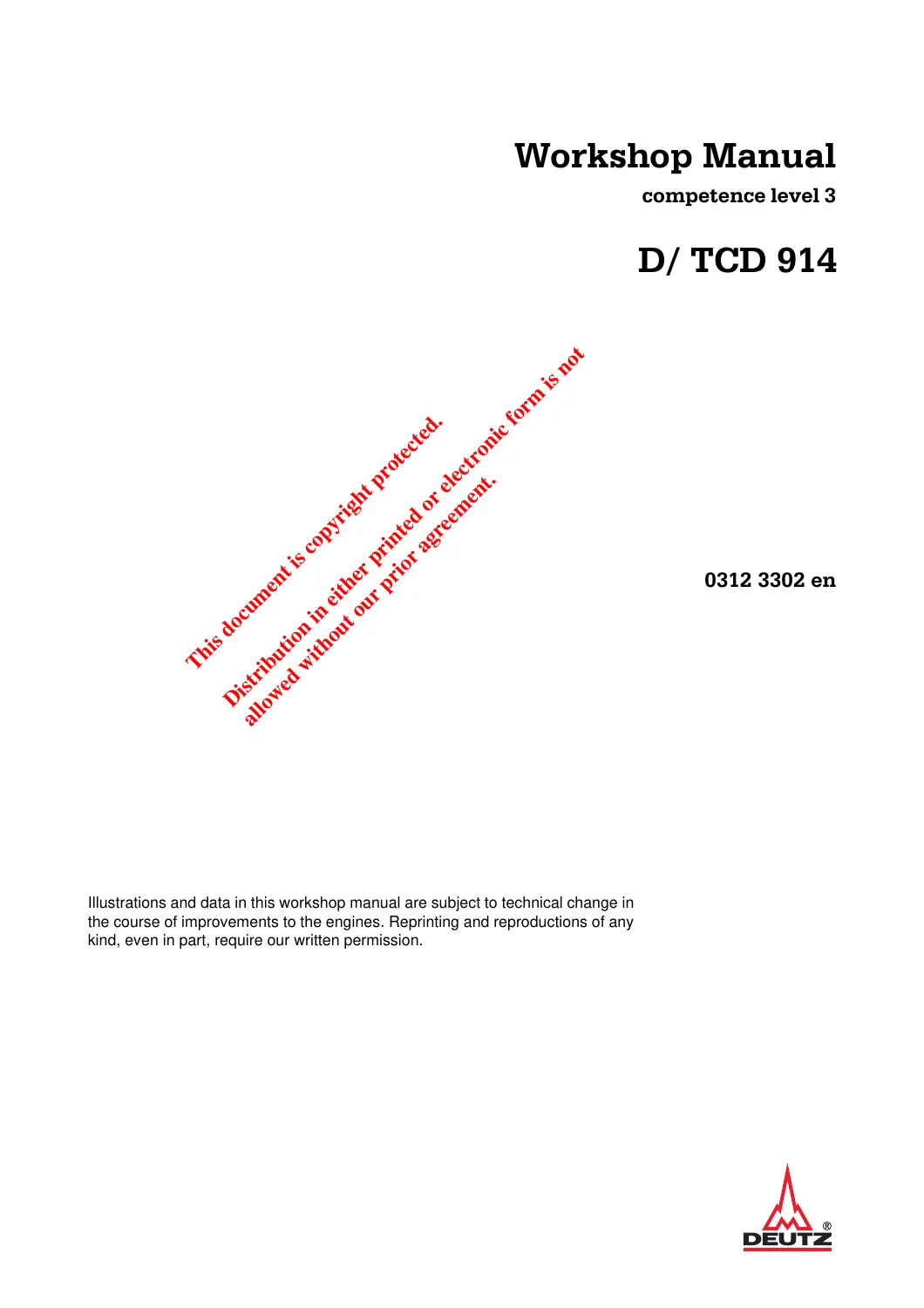
Deutz D 914 and TCD 914 Engine Competence Level 3 Workshop Service Manual
Original price was: $39.95.$24.95Current price is: $24.95.
Comprehensive Competence Level 3 workshop service manual for Deutz D 914 and TCD 914 modular diesel engines. Covers complete teardown, overhaul, machining procedures, timing gear setup, and precision tightening specifications across 3, 4, 5, and 6-cylinder variants in 340 illustrated pages.
Description
Complete Workshop Service Manual for Deutz D 914 and TCD 914 Engines
The Deutz D 914 and TCD 914 Engine Competence Level 3 Workshop Service Manual provides professional mechanics, field technicians, and rebuilding facilities with complete factory technical instructions for servicing, overhauling, and machining Deutz 914 series modular diesel engines. Engineered for air-cooled, naturally aspirated D 914 powerplants and turbocharged TCD 914 engines spanning 3, 4, 5, and 6-cylinder configurations, this comprehensive 340-page technical reference covers standard shop maintenance as well as complex reconditioning operations. Whether you are conducting in-frame maintenance, troubleshooting fuel injection pump timing, setting valve clearances, or completely re-machining cylinder seating faces on the crankcase, this official workshop documentation delivers exacting factory tolerances, procedural step-by-step job cards, and specialized tool instructions.
File Details
- Document Type: Workshop Manual (Competence Level 3)
- Engine Series Covered: Deutz D 914 & TCD 914 (L03, L04, L05, L06)
- Publication Order Number: 0312 3302 en
- Edition & Date: 1st Edition, 12/2006
- Publisher: DEUTZ AG Service Information Systems (Cologne, Germany)
- Language: English
- Page Count: 340 pages
- File Format: PDF format
Structure of Competence Level 3 Documentation
This technical publication organizes engine service tasks through standardized job cards categorized into distinct competence levels. Standard mechanical replacement, inspection, and assembly procedures are designated under W job cards, detailing straightforward workshop repairs with standard and commercial workshop tooling. Complex reconditioning procedures requiring specialized machinery—such as valve seat cutting, valve guide reaming, cylinder head base refacing on a lathe, and crankcase top deck flycutting—are cataloged under I job cards. Technicians can rapidly cross-reference required preparatory tasks, special tools, test tolerances, and torque angles directly on each individual card.
Chapters Covered
- 1 Foreword – Scope of delivery, intended engine use, safety prerequisites, warranty conditions, and genuine DEUTZ replacement parts guidelines.
- 2 General – Engine development background, operating conditions, maintenance compliance, and specialist servicing recommendations.
- 3 User notes
- 3.1 General – Manual documentation layout and baseline engine technical revisions.
- 3.2 Specifications – Safety regulations, accident prevention rules, working around high-pressure fuel systems, and fuel spray personal safety.
- 3.2.1 Accident prevention and safety regulations – Safety practices for personnel, machine room ventilation, fire safety, and running test procedures.
- 3.2.2 Cleanliness instructions and measures for handling the DEUTZ Common Rail System – Component sealing, lint-free cleaning protocols, and workshop environment standards.
- 3.2.3 Disposal regulations – Environmental management, recycling, and operating fluid handling.
- 3.3 Operating manual and workshop manual – System boundaries and documentation structure.
- 3.4 Job cards – Explanations of documentation types (W and I), maintenance groups (00 through 13), component grouping, and serial numbering patterns.
- 3.5 Explanation of symbols – Hazard warnings, critical damage notices, tool callouts, and technical value indicators.
- 4 Technical data
- 4.1 Testing and setting data – General engine dimensions, cylinder bore, piston stroke, compression ratios, valve geometry, crankshaft dimensions, bearing clearances, and cylinder firing order charts.
- 4.2 Tightening specifications – Pre-clamping torques, degree-of-rotation angles, thread lubrication requirements, and torque sequences for all engine fasteners.
- 5 Job card overview
- 5.1 Sorted alphabetically – Cross-reference index sorted by repair activity description.
- 5.2 Sorted numerically – Numeric directory sorted by job card identifier from group 00 to 13.
- 5.3 Job card references – Dependency mapping showing prerequisite job cards required before starting specific tasks.
- 6 Job cards
- 00 General – Checking compression pressure (W 00-02-06), mounting/demounting engine on assembly block 6066 (W 00-05-01).
- 01 Cylinder head – Valve clearance adjustment (W 01-01-01), rocker arm and bracket disassembly/inspection (W 01-02-02), finding top dead centre (W 01-02-05), cylinder head removal and installation (W 01-04-04), repairing cylinder head sealing surface on a lathe (I 01-04-08), measuring piston distance with lead wire (W 01-04-09), removing and installing valves (W 01-05-01), checking valve stem wear (W 01-05-04), valve guide renewal and reaming (I 01-06-02), checking valve guide tilt clearance (W 01-06-03), valve seat ring replacement and cutting (I 01-07-03), checking valve lag dimensions (W 01-07-08).
- 02 Drive system – Crankshaft axial backlash measurement (W 02-01-04), crankshaft inspection and hardness testing (W 02-01-07), front and rear crankshaft radial seal replacement (W 02-02-02, W 02-02-04), connecting rod inspection and alignment checking (W 02-03-01), crankshaft removal and installation (W 02-04-01), piston inspection and micrometer checks (W 02-09-07), piston ring groove and end gap clearance checks (W 02-10-03), piston cooling spray nozzle renewal (W 02-15-01).
- 03 Crankcase – Crankcase breather overhaul for TCD 914 (W 03-01-11), removing and installing pistons and cylinder barrels (W 03-02-04), cylinder bore measurement (W 03-03-01), front gear cover removal/installation (W 03-08-01), rear flywheel-side cover servicing (W 03-09-01), flywheel connection housing removal/installation (W 03-09-04), resurfacing crankcase cylinder seating surfaces with portable returning fixture 150020 (I 03-10-01), camshaft bushing replacement (W 03-11-01).
- 04 Engine control – Idler gear bearing servicing (W 04-04-07, W 04-04-08), camshaft removal, inspection, and journal dimension testing (W 04-05-05, W 04-05-06).
- 06 Exhaust system / Charging – Exhaust manifolds for D 914 and TCD 914 (W 06-01-05), intake manifolds (W 06-02-03), charge air piping and lines (W 06-02-05), turbocharger overhaul and oil pipe connections (W 06-06-04), exhaust gas recirculation valve and lines (W 06-09-06, W 06-09-07).
- 07 Fuel system – Injection line replacement (W 07-03-01), inline fuel injection pump removal, timing, and installation (W 07-04-01), static beginning of injection timing check using locking pin (W 07-06-01), start of injection setting using high-pressure tester 101500 (W 07-06-02), fuel injector removal and stuck injector extraction (W 07-07-01), fuel injector bench testing, chatter test, and opening pressure checks (W 07-07-05), fuel line connections (W 07-10-06).
- 08 Lube oil system – Engine oil pump replacement and gear backlash adjustment (W 08-04-05), oil suction pipe installation (W 08-04-06), oil pan removal and sealing (W 08-04-07), oil cooler servicing for D 914 and TCD 914 (W 08-08-02), oil filter head overhaul (W 08-11-07), oil pressure switch renewal (W 08-11-08).
- 09 Cooling system – Axial cooling blower removal/installation (W 09-11-01), cooling fan hub teardown, bearing replacement, and reassembly (W 09-11-02).
- 12 Other components – Torsional vibration damper replacement (W 12-01-04), V-belt tensioning and inspection with tester 8115 (W 12-02-02), automatic V-belt tensioner complete overhaul (W 12-02-05, W 12-02-06), flywheel removal and installation (W 12-06-01), flywheel starter ring gear renewal (W 12-06-03).
- 13 Electrical system – Alternator service and wiring terminal identification (W 13-02-03), starter motor replacement (W 13-03-02).
- 7 Standard tools – Commercial tool specifications including compression tester 8005, nozzle tester 8008, socket insert 8012, flare nut claw wrench 8018, belt tension gauge 8115, filter strap 8119, cleaning brush 8167, angle disc 8190, and spring band pliers 9090.
- 8 Special tools – Detailed catalog of DEUTZ special service tools including assembly block 6066, compression adapter 100170, dial indicator 100400, TDC setting tool 100640, pointer 100740, degree scale 100910, high-pressure spill pump 101500, injector puller 110030, pin wrench 120040, valve spring lever 121120, cylinder head lathe clamp 125500, ring compressor 130600, seal installation sleeves 142060/142080, crankcase resurfacing fixture 150020, and slide hammer 150800.
Together, these structured sections equip the technician with an uncompromised repair resource. Rather than presenting generic overhaul advice, the document provides explicit disassembly sequences, photographic guidance, component clearance criteria, and precise reassembly tolerances tailored specifically to the physical engineering of the Deutz 914 engine family.
Comprehensive Technical Data & Clearance Specifications
Accurate engine rebuilding requires adherence to rigid factory tolerances. The technical data chapter within the Deutz D 914 and TCD 914 Engine Competence Level 3 Workshop Service Manual supplies an exhaustive array of testing and setting values:
Engine Bore & Stroke
Standard cylinder bore is 102.00 mm (tolerance +0.01/+0.05 mm, wear limit 120.10 mm, 1st oversize 102.50 mm); stroke is 132.00 mm.
Displacement & Weights
D 914 L03 (3,236 cm³, ~270 kg), D 914 L04 (4,314 cm³, ~300 kg), D 914 L05 (5,393 cm³, ~380 kg), D 914 L06 and TCD 914 L06 (6,472 cm³, ~410 kg).
Compression Data
Compression ratio is 20.9:1 for naturally aspirated D 914 models and 19.0:1 for turbocharged TCD 914 engines. Compression test pressure ranges from 2,000 to 3,000 kPa (20 to 30 bar).
Firing Sequences
3-cylinder: 1-2-3; 4-cylinder: 1-3-4-2; 5-cylinder: 1-2-4-5-3; 6-cylinder: 1-5-3-6-2-4. Counter-clockwise rotation looking onto the flywheel.
Valve System Geometry
Inlet valve guide bore in head: 15.00 mm (+0.011 mm, H6); standard valve seat ring bore inlet: 45.50 mm (+0.025 mm, H7); standard exhaust seat ring bore: 40.00 mm (+0.025 mm, H7). Inlet valve stem diameter is 7.96 mm (-0.015 mm, fit h7); exhaust valve stem diameter is 7.94 mm (-0.020 mm). Valve guide stem clearance: inlet 0.045–0.075 mm (wear limit 0.15 mm); exhaust 0.065–0.100 mm (wear limit 0.20 mm). Valve face seat angles are 45°. Valve spring free untensioned length is 66.0 mm.
Valve Clearance & Piston Distance
Valve clearance on a cold engine (<80°C oil temp, cooling time min. 30 min) is set to 0.15 mm (+0.15 mm) for both intake and exhaust. Piston protrusion/distance from cylinder head is 0.80–0.90 mm (+0.05 mm) on D 914 engines and 0.90–1.00 mm on TCD 914 engines, adjusted via color-coded cylinder shims ranging from 3.00 mm to 3.90 mm in 0.05 mm increments.
Crankshaft & Journal Tolerances
Main bearing journal diameter: 75.00 mm (-0.010/-0.029 mm, fit g6, two 0.25 mm undersize stages down to limit 73.50 mm). Con rod journal diameter: 66.00 mm (-0.029 mm, fit g6, undersize limit 64.50 mm). Crankshaft axial end play is 0.15–0.40 mm; radial run-out deviation limit is 0.06–0.08 mm. Journal surface hardness minimum is 55 HRC.
Piston Rings
Joint end gap for 1st ring (marked TOP, yellow): 0.30–0.50 mm; 2nd ring (marked TOP, green): 0.40–0.65 mm on D 914 (0.80–1.00 mm on TCD 914); 3rd oil control ring: 0.25–0.40 mm. Piston ring gaps staggered 120° apart; oil ring spiral expander gap staggered 180° from ring joint.
Fuel Injection & Oil Pressures
Fuel injector opening pressure is 22.0–22.8 MPa (220–228 bar). Lubricating oil pump idler tooth backlash is calibrated to 0.10 mm. V-belt installation tension on generator/blower is 650 N new, checking at 400 N (+/-50 N) after 15 minutes of full-load running.
Torque Tightening Specifications & Angle Procedures
The manual provides explicit pre-clamping values and angle-of-rotation tightening procedures for high-stress engine fasteners to ensure reliable clamping force without thread yield:
- Cylinder Head Screws (A01 001): Pre-tighten diagonally to 30 Nm, followed by three progressive 45° angle steps and a final 30° step (+45° +45° +45° +30°). Threads lightly oiled. Maximum screw length limit without head is 218.5 mm (nominal 217 mm).
- Main Bearing Caps (A02 010): Renew screws, lightly oil threads. Pre-torque to 30 Nm, then turn +60° and +45°. Tighten from center bearing cap outwards.
- Connecting Rod Cap Bolts (A02 020): Renew screws, lightly oil threads. Pre-torque to 30 Nm, then apply two angle steps of +60° and +30°.
- Flywheel to Crankshaft (A12 001): Renew bolts. Pre-torque to 30 Nm, followed by a 60° rotation step. Long bolts (M10x1x135) tightened to 30 Nm +60°.
- Torsional Vibration Damper (A12 030): Renew screw, apply DEUTZ S2 lubricant to threads and contact face. Note left-hand thread! Pre-torque to 50 Nm, then turn through +210° using angle disc 101910 and counter-support 143400.
- Rocker Arm Bracket Nut (A01 002): 28 Nm (lightly oiled).
- Valve Adjuster Lock Nut (A01 003): 22 Nm.
- Cylinder Head Cover Nut (A01 004): 12 Nm.
- Crankcase Locking Plugs (A03 007): M12x1.5 micro-encapsulated screws torqued to 20 Nm (always renew). M20x1.5 torqued to 56 Nm.
- Oil Drain Plug (A03 031): M22x1.5 inserted dry to 80 Nm; M30x1.5 inserted dry to 150 Nm.
- Idler Gear Bearing Screw (A04 011): Pre-clamp to 30 Nm, then tighten +30°.
- Exhaust Manifold Nuts (A06 001): D 914 standard nut: 42 Nm; TCD 914 copper-plated nut: 35 Nm (tighten from center outwards).
- Turbocharger Mounting (A06 020): 50 Nm on exhaust flange.
- Fuel Injector Clamping Shoe (A07 001): 25 Nm (lightly oiled thread).
- Fuel Injection Pump Flange (A07 012): 44 Nm. Clamping nut for injection pump drive gear (A07 083, M20x1.5): 180 Nm.
Professional Workshop & Field Overhaul Capabilities
This Competence Level 3 workshop manual provides complete technical coverage for heavy rebuilding operations:
Precision Valvetrain Overhaul
Step-by-step procedures for driving out worn valve guides from oven-heated cylinder heads (220°C), checking guide bores with limit plug gauges, installing replacement guides, reaming to finished H6 size without chatter marks, and cutting valve seat rings with carbide milling tools or on a lathe.
Piston Protrusion & Compression Setting
Detailed methodology for laying 2 mm lead wire across the piston crown, torquing cylinder heads to test specification (40 Nm + 45°), rotating the engine through 360°, measuring crushed lead thicknesses with an external micrometer, and calculating exact shim ring thicknesses (3.00 mm to 3.90 mm) to maintain factory compression ratios.
Crankcase Cylinder Deck Machining
Dedicated operational instructions for mounting the portable returning fixture 150020 onto the crankcase deck, aligning centering fingers within the cylinder bores, setting depth cuts in 0.20 mm increments, and hand-facing damaged cylinder seat surfaces to restore perfect deck heights.
Timing Train & Injection Timing
Clear photographic guides for indexing gear tooth alignment marks between the crankshaft pinion, central idler gear, camshaft gear, mass balancer shafts (on 4-cylinder engines), and fuel injection pump gear. Precise static fuel injection timing verification using degree disc 100910 and pointer 100740, or high-pressure spill timing with hand pump 101500.
Subassembly Rebuilding
Full teardown, internal inspection, ball bearing replacement, and reassembly instructions for the engine axial cooling blower, oil pump, and automatic V-belt tensioning unit.
Why This Technical Manual Is Essential
Working on precision air-cooled Deutz diesel engines without exact factory data risks severe mechanical failures. Incorrect piston protrusion causes piston-to-valve contact or inadequate cylinder compression. Over-tightening cylinder head or main bearing bolts without angle-controlled torque parameters leads to fastener stretching, distorted cylinder barrels, and blown cylinder base gaskets. Missing the subtle timing marks on the idler gear or misidentifying valve overlap on internal exhaust gas recirculation (EGR) camshafts can result in incorrect valve timing and severe engine damage.
By following the proven repair procedures, clearance tables, and tightening angles established in this Deutz D 914 and TCD 914 Engine Competence Level 3 Workshop Service Manual, repair facilities, fleet mechanics, and equipment operators can perform overhauls that restore factory reliability, optimize fuel efficiency, and ensure long engine service life. Available as an instant, high-resolution PDF download with no shipping delays, this document is viewable across all computer, tablet, and smartphone devices, and can be printed in whole or by individual job card directly at the workbench.
Reviews
There are no reviews yet.