
Kubota V3307-CR-TE4 Common Rail System Diagnosis Manual 9Y110-02440 PDF
Original price was: $39.95.$23.95Current price is: $23.95.
Complete 317-page Kubota V3307-CR-TE4 Common Rail System Diagnosis Manual (document 9Y110-02440) covering CRS layout, wiring, data monitor signals, symptom-based troubleshooting and step-by-step procedures for every DTC the ECU can set.
Description
Kubota V3307-CR-TE4 Common Rail System Diagnosis Manual – 9Y110-02440
This is the complete Kubota V3307-CR-TE4 Common Rail System Diagnosis Manual, document number 9Y110-02440, published in June 2013 for the four-cylinder V3307-CR-TE4 common rail diesel engine fitted to Kubota tractors. Where a workshop manual tells you how to take the engine apart, this V3307-CR-TE4 diagnosis manual tells you how to figure out what is wrong with it. Every layer of the Bosch-style common rail system is opened up in sequence – how the rail, supply pump, SCV, injectors and ECU interact, what each sensor reading should be, how to read a fault through the Kubota Diagramster tool, and what to physically measure when a DTC lands. It is the troubleshooting counterpart to the engine service manual and assumes you already know your way around a diagnosis tool, a multimeter and an insulation tester.
File Details
- Manual type: Common Rail System Diagnosis Manual
- Brand / manufacturer: Kubota
- Engine model: V3307-CR-TE4
- Document number: 9Y110-02440
- Publication date: 2013.06
- Language: English
- Page count: 317 pages
- File format: PDF
- Publisher: Kubota Farm & Industrial Machinery Service, Ltd.
Chapters Covered
- Safety First – Before Servicing and Repairing, Safety Starting, Safety Working, Avoiding Fires, Ventilating the Work Area, Preventing Acid Burns, Fluid Disposal, Preparing for Emergencies
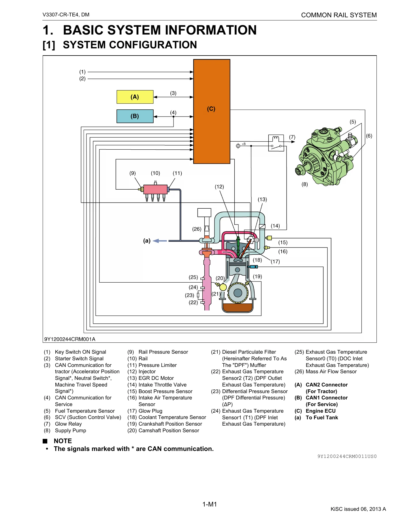
- Common Rail System – Basic System Information
- System Configuration
- Fuel System
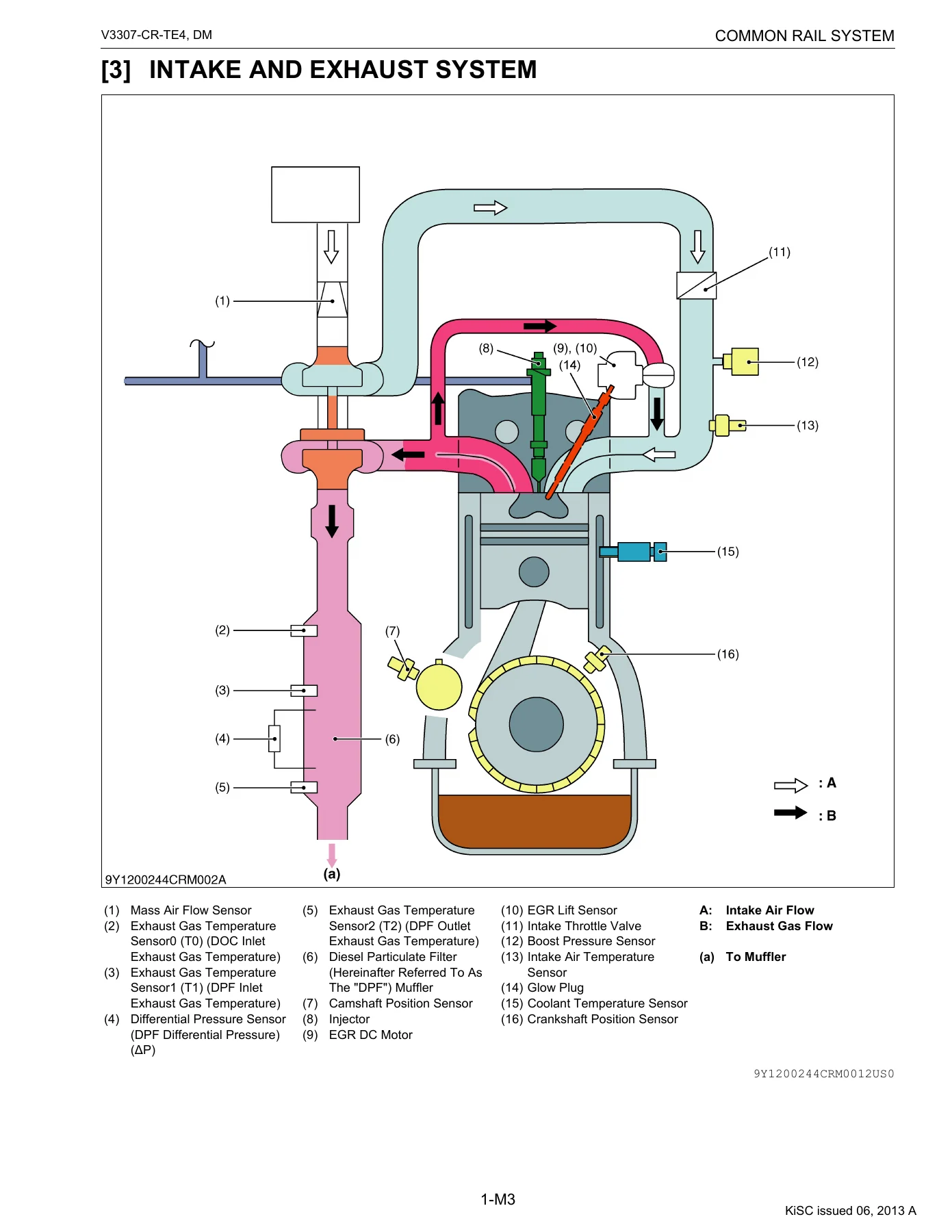
- Intake and Exhaust System
- Wiring Diagram – System Wiring Diagram
- Available Data Monitor Signals (Level 1) – Monitor Items and Normal Value
- ECU Terminal Layout 1 (A: 96 Pins)
- ECU Terminal Layout 2 (B: 58 Pins)
- General – Overall Diagnostic Procedure, Questioning, List of Malfunction Symptoms, Actions for Non-Recurring Malfunctions
- Diagnostic Tool Connection Procedure – Connector Positions, Connection Procedure, Checking the Communication Operation of the Interface (DST-i), Checking the Operation of the ECU
- Active Test and Supply Pump Difference Learning
- Diagnosis by Malfunction Symptom – List of Malfunction Causes by Symptom
- Diagnosis by Symptom – Engine Warning Light Comes On, Engine Does Not Start, Takes A Long Time Before Engine Starts, Idle Failure, Engine Noise, High Fuel Consumption, Poor Acceleration, Abnormal Black Smoke Emitted, Abnormal White Smoke Emitted, Engine Stalls On Deceleration
- Diagnostic Procedure by DTC – DTC List
- Diagnostic Procedure by DTC – Individual fault-code procedures (P0016 through to U0083)
- Inspection Procedure for Each System – Air Intake System, Fuel System, Electric System
The contents read like the internal workflow of a Kubota technician: start with the safety brief, understand the CRS architecture, learn which data monitor signals to trust, then work through the fault. The bulk of the V3307-CR-TE4 CRS diagnosis manual is the DTC section, where each code gets its own procedure with preconditions, set parameters, system actions, warning-light behaviour, recovery conditions and the physical checks that confirm the root cause. Around it sits practical material that is easy to overlook until you need it – the pinout of both ECU connectors, the normal idle and no-load maximum-speed rail pressure values, the resistance-versus-temperature tables for each thermistor, and the reference waveforms for the EGR valve and glow relay active tests.
What You Can Diagnose With This Kubota V3307-CR-TE4 Diagnosis Manual
Because the manual covers the whole control chain, one document lets you chase faults from three different directions. From the driver’s complaint you can drop into the symptom section and be told exactly which DTCs to expect, which sensor to monitor first and which joint or pipe to inspect. From the fault code you can drop into the DTC list and go straight to a numbered procedure with factory-spec values beside every measurement. From raw data you can hook up the tool, watch rail pressure, boost pressure, EGR position, exhaust gas temperatures and injector common-rail voltages, and compare them against the normal-value tables printed in the Level 1 data monitor chapter. The pressure-system DTCs – P0087 pressure limiter emergency open, P0088 high rail pressure, P0089 SCV stuck, P0093 fuel leak in the high-pressure system and P1274 / P1275 pump seizing – are grouped and share a common diagnostic path, which matters because in practice several of them can set at the same time. Injector drive-circuit codes (P2146 to P2151), EGR and intake throttle codes, exhaust gas temperature codes (P0543 through P3004) and the CAN bus codes (U0075, U0076, U0077, U0081 to U0083) each get their own dedicated sequence of checks.
Reference Values You Will Use Again and Again
Scattered through the procedures are the numbers that decide whether a component is good or bad. Idle rail pressure is quoted at 40 to 50 MPa (410 to 500 kgf/cm2, 5800 to 7200 psi); full no-load maximum speed is 95 to 115 MPa. The rail pressure sensor should output roughly 1.0 V at key-on, 1.65 to 1.80 V at idle and 2.50 to 2.85 V at no-load maximum speed. Injector coil resistance is specified as 1.5 ohm or lower at the ECU connector and 0.35 to 0.55 ohm across the injector terminals. SCV resistance is around 2.1 ohm with 100 M-ohm or higher insulation to the valve body. Intake air, coolant and fuel temperature sensors all share similar thermistor curves, and the exhaust gas temperature sensors have their own 18.3 k-ohm at 100 C down to 2.30 k-ohm at 250 C table. Those are the reference points that turn guesswork into diagnosis.
Wiring, Active Tests and Supply Pump Learning
The system wiring diagram chapter is the map for everything else. It shows both ECU connectors pin by pin, with the twisted-pair injector harness, the shield cables for the NE and G sensors, the CAN1 and CAN2 buses, the glow relay drive, the intake throttle valve motor, and the individual signal and ground returns for each sensor. The active test section covers the four operations the tool can drive directly – injector non-injection instruction (one cylinder at a time), EGR actuation, glow relay cycling and supply pump difference learning. The pump learning procedure is explained in full, including the conditions under which it can run (engine warmed up, machine stopped, neutral switch on, accelerator at 0 percent) and how to read the pump learning condition and pump difference learning correction value afterwards.
IMAGES PREVIEW
Instant PDF Delivery
The Kubota V3307-CR-TE4 Common Rail System Diagnosis Manual 9Y110-02440 is delivered as a PDF download the moment payment clears – no shipping, no waiting for a printed copy to arrive. It opens on any laptop, tablet or phone, and individual pages can be printed for the workshop bench when you are working through a multi-step procedure. Because the file is organised by DTC and by symptom, you can jump straight to the page that matters rather than leafing through a bound manual with greasy fingers. Whether you are chasing a single intermittent fault, preparing a service bay for common rail diagnostics, or keeping a copy in the workshop library for the next V3307-CR-TE4 that rolls in, this manual gives you the factory procedure and the factory numbers in a form you can actually use.
Reviews
There are no reviews yet.