
Deutz-Fahr Agrofarm 410 420 430 Workshop Manual – Repair, Diagnostics & Wiring PDF
Original price was: $49.95.$29.95Current price is: $29.95.
Comprehensive Deutz-Fahr Agrofarm workshop manual covering AGROFARM 410, 420 and 430 tractors, with technical data, repair and overhaul procedures, electronic diagnosis, calibration, hydraulic information and detailed wiring diagrams. Includes engine, transmission, PTO, axles, brakes, hydraulics, cab systems, electrical equipment, front and rear lifts and extensive component-level service procedures.
Description
Deutz-Fahr Agrofarm 410 420 430 Workshop Manual – Repair, Diagnostics & Wiring PDF
The Deutz-Fahr Agrofarm 410 420 430 Workshop Manual – Repair, Diagnostics & Wiring PDF is a detailed technical reference for repair work on AGROFARM 410, AGROFARM 420 and AGROFARM 430 tractors. Across 956 pages, it combines machine specifications, component descriptions, dismantling and refitting procedures, adjustment data, diagnostic routines, electronic calibration instructions, hydraulic schematics and a substantial electrical wiring section. The manual is written for repair technicians and is structured around practical fault diagnosis, safe repair methods, dimensional checks, inspection procedures, tightening information and adjustment data.
File Details
- Manual type: Workshop Manual
- Brand: DEUTZ-FAHR
- Models: AGROFARM 410, AGROFARM 420, AGROFARM 430
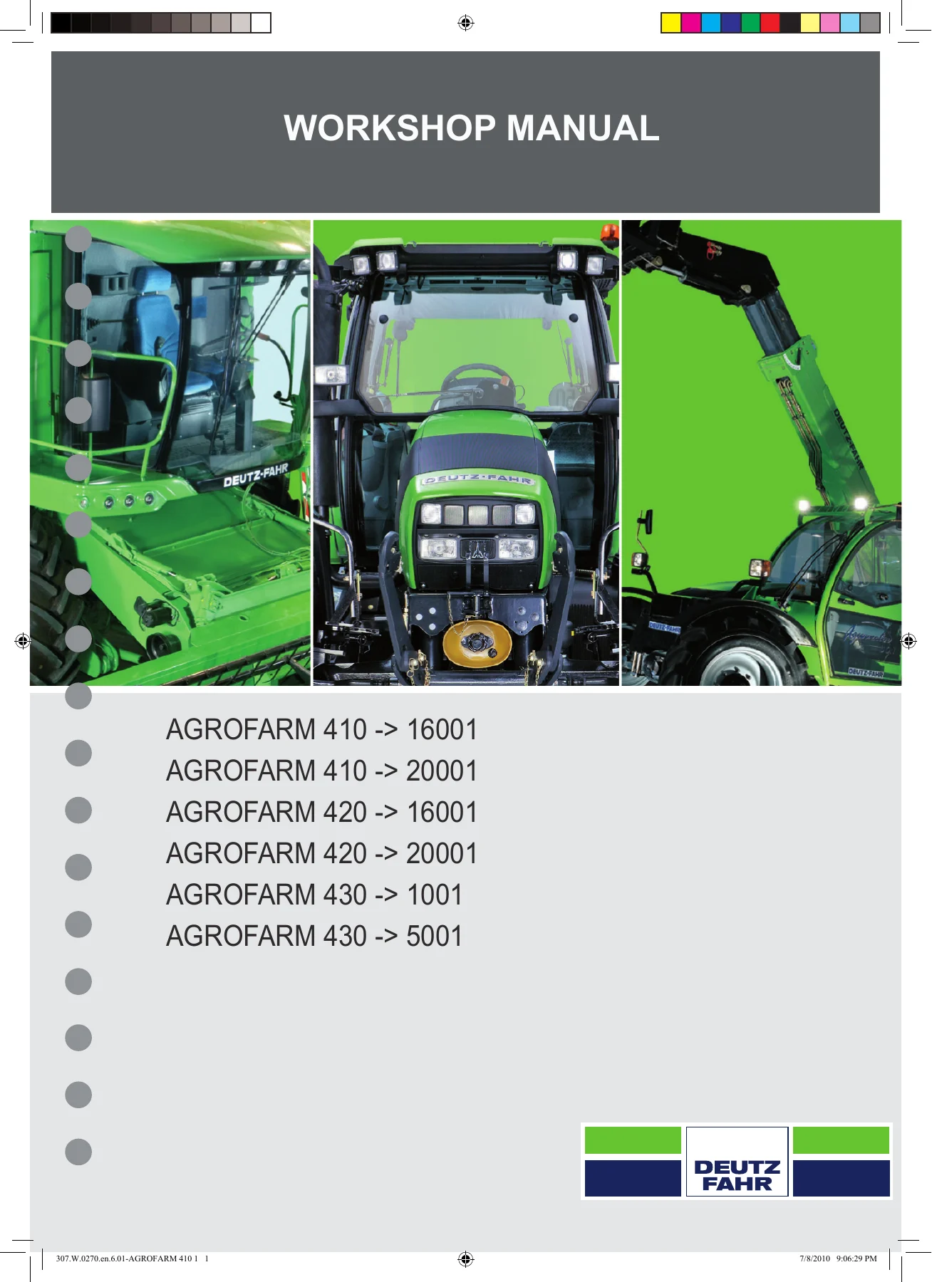
- Cover references: AGROFARM 410 -> 16001; AGROFARM 410 -> 20001; AGROFARM 420 -> 16001; AGROFARM 420 -> 20001; AGROFARM 430 -> 1001; AGROFARM 430 -> 5001
- Language: English
- Page count: 956 pages
- File format: PDF
- Document number: 307.W.0270.en.6.01
Workshop Information for Major Tractor Systems
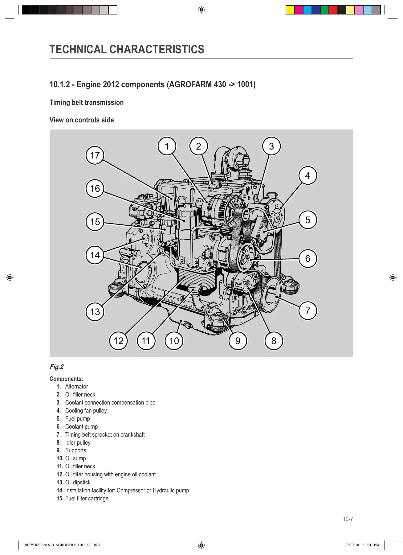
This Deutz-Fahr Agrofarm 410 420 430 workshop manual goes beyond routine maintenance information. Its technical-characteristics section explains the construction and operating principles of major assemblies before the repair section moves into removal, disassembly, adjustment, inspection and refitting work. Engine information includes TD 2012 and TCD 2012 data, component identification, compression checks, piston overhang, valve-clearance work, cylinder-head procedures, injector removal, cooling-system components, turbocharger work and associated tightening specifications.
The transmission material describes a configuration with five synchronised speeds and four ranges, giving 20 forward and 20 reverse ratios, together with the shuttle, Hi-Lo unit, gearbox, range gearbox, differential, four-wheel-drive components and rear PTO. PTO coverage includes 540 and 1000 versions as well as the 540, 540 ECO, 1000 and 1000 ECO arrangement and Syncro PTO information where fitted. Detailed sectional illustrations identify internal shafts, clutches, pistons, gears, bearings, synchronizers, differential components and engagement mechanisms before the intervention chapters provide dismantling and adjustment procedures.
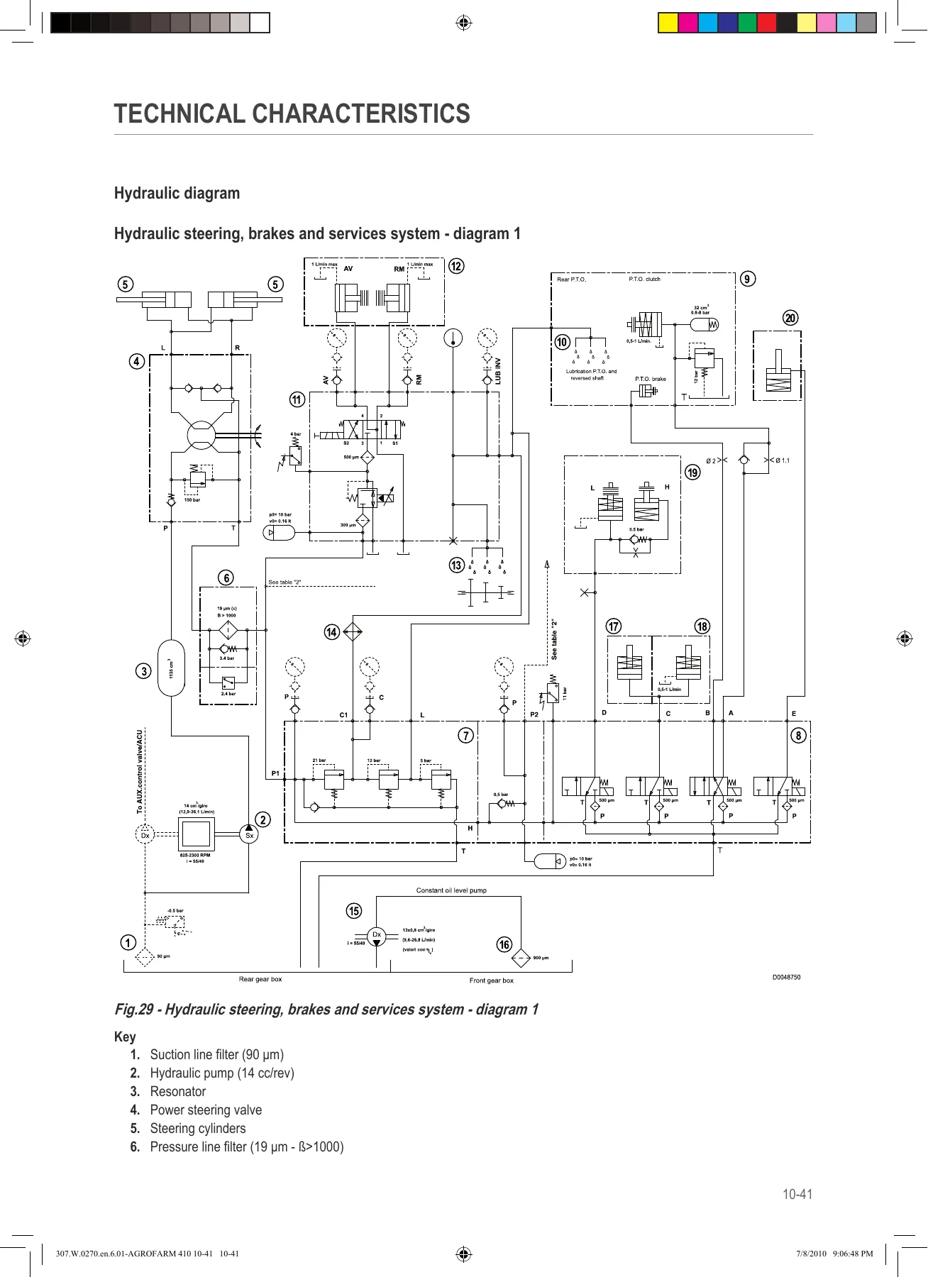
Hydraulic coverage is similarly extensive. The manual separates the system into steering, brakes and services and the lift and remote-control-valve circuit, then provides schematics and component information for the pumps, power steering, remote valves, lift control valve, brake circuits, trailer braking, Park Brake, pressure-holding valves and shuttle solenoid valve assembly. The technical section identifies a 14 cc/rev steering circuit gear pump with a maximum operating pressure of 155 bar and a 22.5 cc/rev lift circuit gear pump with a maximum operating pressure of 190 bar. Hydraulic diagrams cover standard arrangements as well as configurations incorporating hydraulic trailer braking, front lift and front loader equipment.
Electronic Diagnosis and Calibration
A major part of this Agrofarm 410 420 430 repair manual is devoted to electronic diagnosis. It explains use of the All Round Tester, including connection to the tractor, monitoring inputs and outputs, viewing transmission information and CAN communication, checking alarms and testing actuators. The tester information covers sensor monitoring, clutch and shuttle parameters, calibration menus, active and passive alarms and engine-related diagnostic data.
The manual also explains the tractor electronic system and CANBUS communication between the shuttle ECU, engine ECU and instrument panel. Procedures are provided for commissioning after electronic component replacement, configuring a replacement instrument panel, setting the tractor type and wheel constant, selecting speed units and programming a replacement shuttle ECU. Shuttle clutch calibration receives substantial attention, with automatic and manual procedures, forward/reverse balance, response and acceleration adjustment and comfort parameters. Engine ECU-related material includes DATASET handling and calibration procedures for the accelerator pedal and hand throttle. Extensive alarm information is included for the engine, hydraulic shuttle, instrument panel and transmission.
Chapters Covered
- 0 – Introduction
- Safety notes and general safety rules
- Safety precautions for removal and refitting operations
- Lifting instructions
- Tightening torques for fasteners and fittings
- Threadlockers, adhesives, sealants and lubricants
- Conversion factors
- 10 – Technical Characteristics
- Engine technical data and Engine 2012 components
- Transmission construction and operating information
- Rear PTO and 2-speed, 4-speed and Syncro PTO systems
- Front axle construction and steering information
- Hydraulic system circuits and schematics
- Steering and lift circuit pumps
- Power steering valve and 6-way remote control valve
- Hydraulic lift control valve
- Braking and hydraulic trailer braking systems
- Park Brake system and Park Brake valve
- Services solenoid and pressure-holding valve assemblies
- Shuttle solenoid valve assembly
IMAGES PREVIEW

- 20 – Calibrations and Electronic Diagnosis
- All Round Tester diagnostic instrument and tractor connection
- Monitor, Parameters, Calibrations, Alarms, Test and Engine menus
- Electronic system and CANBUS operation
- Engine ECU and Shuttle ECU
- Instrument-panel replacement and tractor configuration
- Wheel constant and speed-unit settings
- Shuttle ECU initialisation and line-end programming
- Automatic and manual shuttle-clutch calibration
- Clutch response, balance, acceleration and comfort parameters
- Clutch pedal, accelerator pedal and hand-throttle calibration
- Engine ECU DATASET procedures
- Engine, hydraulic shuttle, instrument-panel and transmission alarms
- 30 – Method of Intervention
- B0 – Engine: separation, belts, compression checks, flywheel, piston overhang, valve train, cylinder head, injectors, cooling components and turbocharger
- C0 – Engine accessories: radiator, air cleaner, intercooler, fuel tank and cooler, starter, exhaust components, fuel supply components, generator and sensors
- D0 – Transmission: oil change, range selector, shuttle, forward and reverse clutches, Hi-Lo, gearbox shafts, differential, 4WD output and PTO assemblies
- E0 – Rear axle: axle assemblies, planet carrier, rear differential and Park Brake
- F0 – Front axle: front support, 4WD axle, steering cylinders, knuckle and half-shaft, differential, bevel gears, planetary reduction and brakes
- G0 – Bodywork, cab and platform: cab, hood, consoles, instrument panel, roof equipment, heating and air-conditioning components
- H0 – Hydraulic system: pumps, steering valve, pressure-relief setting, remote valve, brake bleeding, braking valves and solenoid assemblies
- L0 – Electrical system: battery, alternator, clutch and throttle sensors, shuttle sensor, steering-column switch and Shuttle ECU
- M0 – Front PTO: PTO assembly, pump, clutch-brake assembly, oil cooler and solenoid valve
- N0 – Front lift: lift assembly and cylinder disassembly
- R0 – Rear lift: complete lift, cylinders, control valve, mechanical draft sensor and 3-point linkage
- S0 – Wheels: front and rear wheels
- V0 – Ballast and towing hitches: towing hitch slide
- 40 – Wiring Diagrams
- Wiring structure, wiring index and components index
- Earthing points, starting and preheating circuits
- Electronic engine control
- Diagnostic and accessory circuits for standard and high-visibility cabs
- Instrument panel and worklight circuits
- Heating and manual climate-control circuits
- Steering-column lighting and windscreen-wiper circuits
- Transmission, PTO, CAN Bus and brake circuits
- Battery, power-supply and preheating wiring harnesses
- Engine, central and drivetrain wiring
- Drivetrain shuttle and cab wiring
- Cab roof, heater and air-conditioning wiring
- Worklight, front-light, wiper and rotating-beacon wiring
- Hydraulic trailer braking and associated electrical connections
Taken together, these chapters provide a technician with a connected view of how the tractor is built, how individual systems operate and how they are serviced. The technical-characteristics material can be used to understand system layouts and reference settings before beginning a repair, while the Method of Intervention section provides component-focused procedures. Diagnostic and calibration chapters support electronic troubleshooting, and the wiring section follows circuits through system diagrams, harness information and connector positions rather than providing only a basic electrical overview.
Mechanical Repair and Overhaul Depth
For drivetrain work, the manual includes procedures for the shuttle assembly, forward and reverse drive clutch assemblies, Hi-Lo components, primary and secondary shafts, range gearbox and differential, rear pinion, four-wheel-drive output shaft, PTO clutch and PTO output arrangements. Rear and front axle sections continue into differential disassembly and adjustment, bevel-gear work, planetary reduction components and braking hardware. These procedures are supported by sectional drawings and component callouts that help identify the parts involved before dismantling.
Engine work ranges from checks such as compression pressure and valve clearance to removal of major components including the cylinder head and turbocharger. The manual also covers cooling, fuel and accessory components including the coolant pump, thermostat, radiator, intercooler, fuel supply pump, starter motor and generator. General workshop information at the front of the manual supplies tightening guidance, fitting torque information, approved categories of threadlocking and sealing products, lifting precautions and rules for removal and refitting operations.
Hydraulic, Brake, Lift and PTO Service
The hydraulic diagrams are useful for tracing oil flow through steering, braking, shuttle, PTO, lift and auxiliary circuits. Component-level information is included for the power-steering valve, remote control valve, hydraulic lift control valve, Park Brake valve, pressure-holding valves and shuttle solenoid valve assembly. The intervention section then covers disassembly or adjustment work on many of these units, including power steering, pressure relief, remote valves, brake bleeding, parking brake controls and service solenoids.
Front PTO and front lift equipment receive dedicated repair sections rather than being treated only as accessories. Rear lift information includes complete lift removal and disassembly, lift cylinders, auxiliary cylinders, lift control valve, mechanical draft sensor and the 3-point linkage. This makes the Deutz-Fahr Agrofarm workshop manual useful for repairs that cross mechanical and hydraulic systems instead of limiting the reference to engine or transmission work alone.
Electrical Schematics and Connector Reference
The final wiring section is extensive, covering complete systems as well as individual harnesses and connector locations. It includes starting and preheating, electronic engine control, instrument panel, transmission, PTO, CAN Bus, brakes, worklights, heating, climate control and wiper circuits. Harness coverage includes battery and power supply wiring, preheating, engine harness variants, central wiring, drivetrain and shuttle wiring, cab power and roof wiring, air-conditioning circuits, worklights, front lighting, wipers, rotating beacon and hydraulic trailer braking connections. Connector-position illustrations accompany many harness sections, helping the reader follow the schematic into the physical tractor.
Repair With the Procedures, Diagrams and Settings in Front of You
The Deutz-Fahr Agrofarm 410 420 430 Workshop Manual – Repair, Diagnostics & Wiring PDF supports a wide range of workshop jobs, from engine checks and component replacement to transmission disassembly, PTO work, axle repair, hydraulic troubleshooting, brake service, electronic commissioning, clutch calibration and electrical fault tracing. Having the specified procedures, tightening information, adjustment data, hydraulic schematics, diagnostic instructions and wiring diagrams together is especially valuable when a repair involves more than one tractor system or when accurate reassembly and calibration are essential.
Delivered as an instant PDF download after purchase, there is no physical book and no shipping delay. Open the manual on a computer, tablet or phone whenever you need it, and print the pages required for a workshop job. For technicians working on the covered AGROFARM 410, 420 and 430 configurations, this manual provides a substantial repair and diagnostic reference in one 956-page file.


Reviews
There are no reviews yet.