
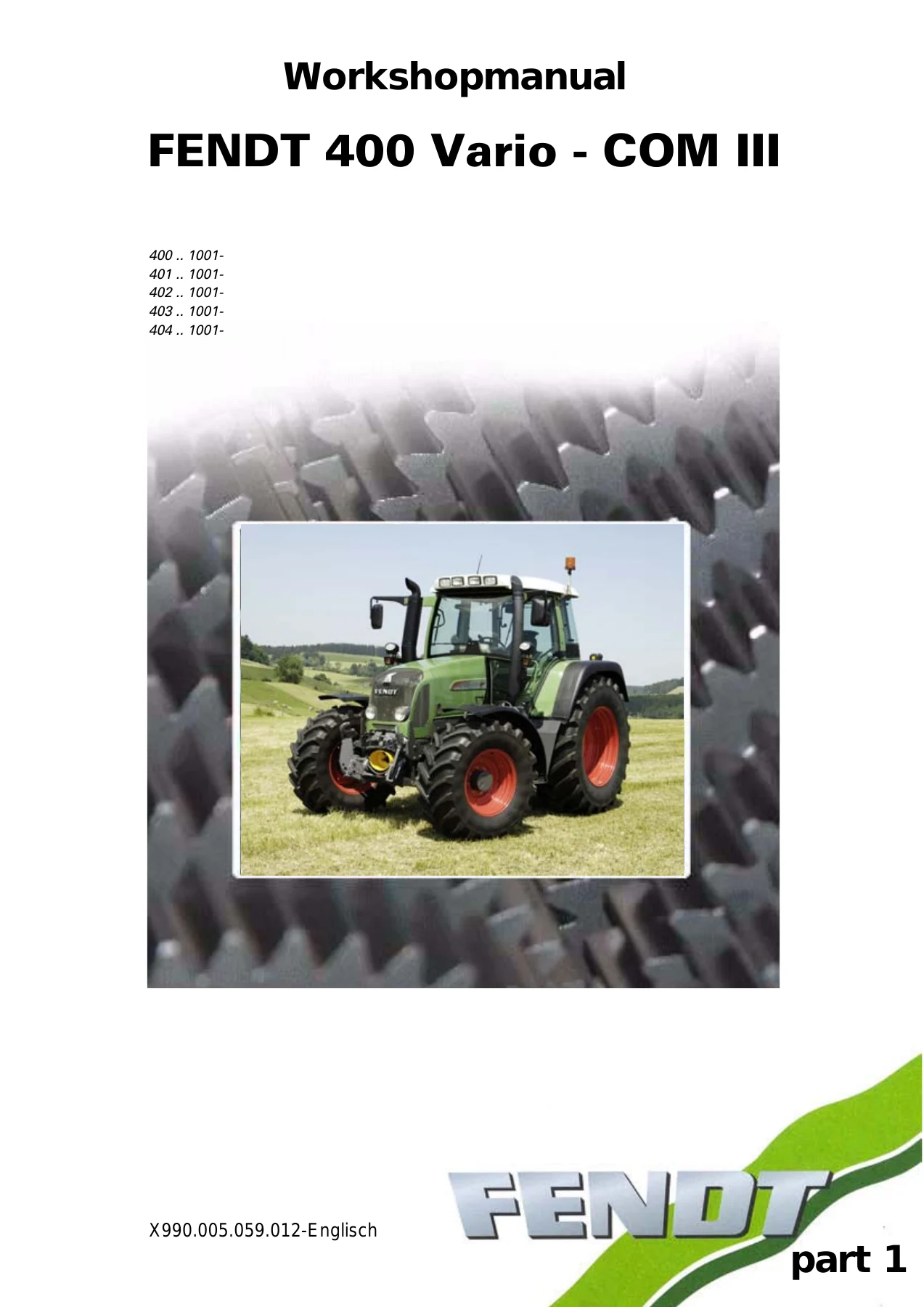
Fendt 400 Vario COM III Workshop Manual Part 1 – 400 401 402 403 404 Tractor Repair PDF
Original price was: $39.95.$24.95Current price is: $24.95.
Part 1 of the Fendt 400 Vario COM III workshop manual covering 400 / 401 / 402 / 403 / 404 tractors – ML 90 Vario transmission, Deutz TCD 2012 engine, hydraulics, brakes, PTO, electronics and full calibration procedures. 558-page PDF, doc X990.005.059.012.
Description
Fendt 400 Vario COM III Workshop Manual – Part 1
This is the first part of the workshop documentation set written for the Fendt 400 Vario COM III tractor series, covering models 400, 401, 402, 403 and 404 from serial ranges 400..1001-, 401..1001-, 402..1001-, 403..1001- and 404..1001- onward. It is the technician-facing companion to the operator’s manual – built for the diagnosis, adjustment, calibration and repair of the ML 90 Vario transmission, the Deutz TCD 2012 L4 engine, the hydraulic system, the brake system and the tractor electronics. Document reference X990.005.059.012, delivered as a 558-page PDF.
File Details
- Manual type: Workshop manual (Part 1)
- Brand: Fendt
- Series: 400 Vario COM III
- Models covered: FENDT 400 / 401 / 402 / 403 / 404 /21/
- Document number: X990.005.059.012
- Language: English
- File format: PDF
- Page count: 558 pages
How the Document Is Organised
The workshop manual is split into registers, each identified by a letter: A – General, B – Faults, C – Documents and Diagrams, D – Component Position, E – Measuring and Testing, F – Setting and Calibrating, G – Repair and H – Service Info. Every component group is then broken down into the same register letters, so a technician moves straight to the exact layer needed for a job – fault code table for the symptom, component location page for the sensor, measuring sheet for the pressure check, then the repair sequence itself.
Chapters Covered
- 0000 Overall system/tractor
- 1005 Transmission/transmission control system
- 1010 Transmission/differential
- 1015 Transmission/axle drive
- 1030 Transmission/hand brake
- 1070 Transmission/brake system
- 1080 Transmission/drive train
- 1100 Transmission/clutch actuation system
- 1200 Transmission/front PTO
- 1220 Transmission/live PTO
- 1320 Transmission/front wheel drive
- 1430 Transmission/hydrodamp
- 2000 Overall system/engine
- 2010 Engine/cylinder head
- 2060 Engine/fuel system
- 2250 Engine/engine pre-heater
- 2312 Engine/lubrication
- 2400 Engine/exhaust system
- 2712 Engine/injectors
- 3020 Front axle/axle body
- 3050 Front axle/suspension
- 3180 Front axle/cardan shaft
- 5200 Vehicle layout/cab mounting, suspension
- 5500 Overall system/air conditioning system
- 8100 Overall system/cab
- 8610 Power lift/EPC electro-hydraulic control
- 8618 Power lift/external control
- 8800 Overall system/compressed air system
- 8810 Compressed air system/air compressor
- 8820 Compressed air system/brake fittings
- 8830 Compressed air system/pipes
- 8890 Compressed air system/air reservoir
- 8900 Overall system/front loader
- 8970 Front loader/piping
- 9000 Overall system/electrical system
- 9420 Hydraulic pump installation/transmission pump
- 9600 Overall system/hydraulic equipment
- 9700 Overall system/electronics
- 9717 Electronics/LBS agricultural bus system
- 9740 Electronics/E-box
- 9770 Electronics/control panel
- 9920 Service/special tools
- 9975 Service/SERDIA – Deutz engine diagnostics program
What This Fendt 400 Vario COM III Workshop Manual Covers
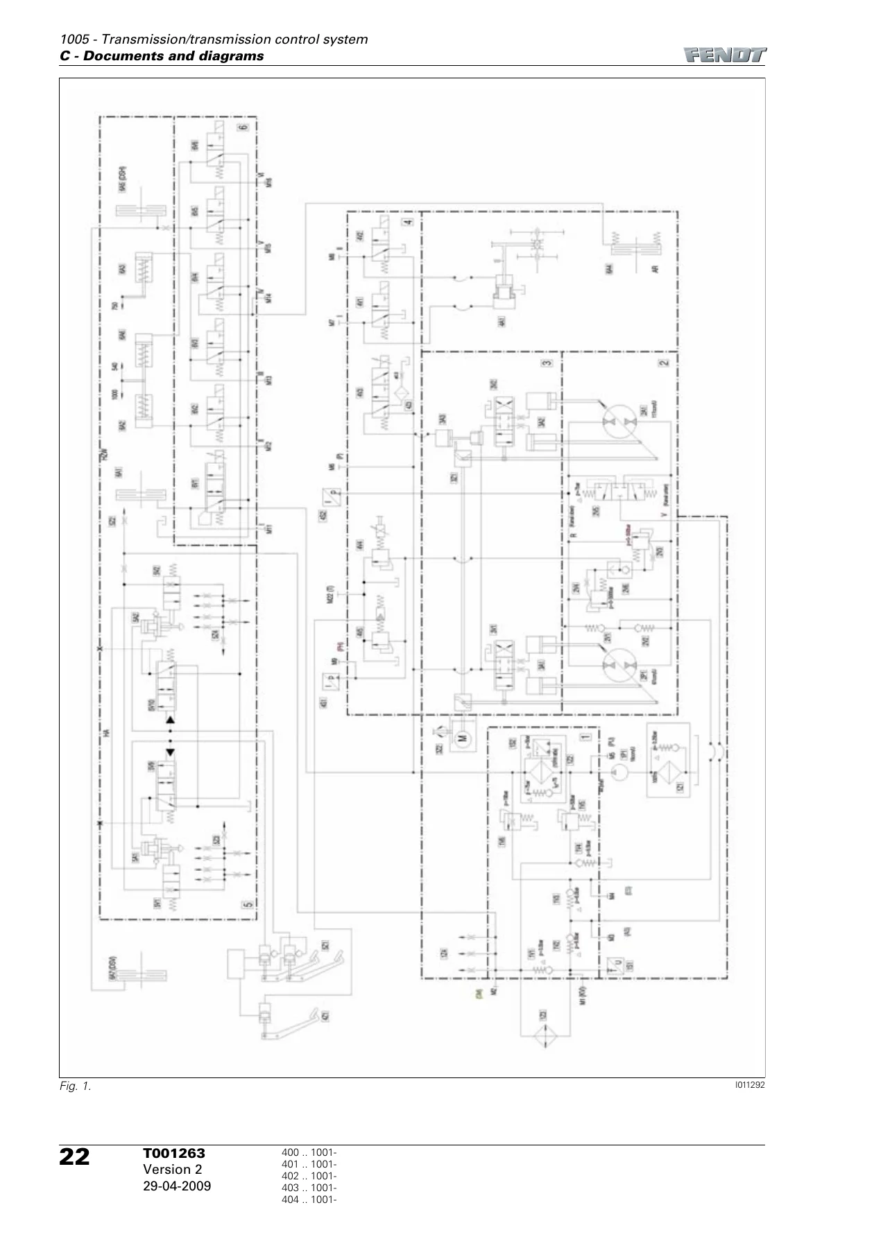
The opening section anchors the whole series: the component overview chart, the documentation layout, safety briefing notes for the front axle suspension, engine, PTO, front loader and brake system, and the metric tightening torque tables for standard and fine-pitch threads. From there the transmission content takes over. The ML 90 Vario transmission is explained hydraulically and functionally – planetary power split between the mechanical and hydrostatic branches, the high-pressure circuit with its variable displacement pump and motor, the two high-pressure limiting valves and the purge valve. Section 1005 walks through the transmission control system functional sequence and the transmission function diagram across its five power-flow states, then goes into the turbo clutch solenoid valve (4V4) and the clutch pressure-limiting valve (4V5) in detail.
Measurement work is covered with actual target values. The transmission pressure measurement chapter gives supply pressure, high-pressure circuit, inlet and outlet pressure and lubrication pressure targets against engine speed, and the same sheet is repeated as a fax template so a workshop can record the numbers as they are read. Enhanced control pressure measurement covers travel range selector 1 and 2, rear PTO clutch, PTO 540 / 750 / 1000, 4WD clutch and differential lock, again with target values per switch position.
Calibration Codes
Part 1 includes the full calibration sequence for the sensors and functions that need teaching after replacement or after mechanical work. Codes listed inside include the rear EPC depth control (8001) and rear power lift position (8002), the front power lift enhanced control (9001) and front power lift position (9002), the crossgate lever for the hydraulic auxiliary valves (1001), the front axle suspension sensor (7666), the rear PTO coupling time (6034) and front PTO coupling time (7034), the clutch pedal sensor (4001), hand throttle (4002), travel range selector sensor (4003), foot throttle sensor (4005), the transmission ratio characteristic (4007), the turbo clutch function (4009) and the throttle pedal resolution (4010). Each code is documented step by step with the display pictograms, the exact working conditions and the fault code tables that appear if the calibration does not complete.
Faults and Diagnostics
The fault section explains how to confirm, call up and delete fault codes on the multifunction display, then presents the fault code tables for the Fendt 400 / 700 / 800 Vario COM III tractors. Entries list the DIN brief description, the cause, the consequences of leaving the fault, the reference wiring diagram, the FENDIAS note and the relevant register. Coverage spans engine control unit A051 EDC 7, the control panel A004, the driving switch A034, the terminal A008 and the electronic data transfer A055. A dedicated terminal A008 diagnostics chapter walks through the four main menu levels, the screen brightness menu, diagnostics 1 with IDEAL / VE / REAL / MEMO bars for transmission ratio adjustment, the speed display, diagnostics 2 with high-pressure transmission sensor, CAN1 messages, target speed, software and hardware versions and load counter, and the ISO / LBS diagnostics page.
Component Position
A very large register D section catalogues electrical and electronic components alphabetically – A002 ECU enhanced control, A004 ECU control panel, A006 keypad, A007 instrument panel, A008 terminal, A009 actuator unit, A011 radar sensor, A014 EPC OBE, A051 EDC 7, A055 data transfer, then B-series sensors (front PTO speed, front axle suspension position, vacuum switch, high-pressure sensors 1 and 2, discharge temperature, engine speed, hydraulic oil temperature, collecting shaft, bevel pinion, travel range detection, clutch pedal, compressed air supply, rear PTO speed, kickout, rear power lift position, draft sensing pins, fuel level, charge air pressure, steering angle, rail pressure, fuel low pressure, crankshaft speed, engine temperature, oil pressure, water in fuel), then E-series lighting, G-series battery and alternator, H-series horn and warning signal, K-series relays, M-series motors, R-series heater flange, S-series switches and buttons, V-series diodes, X-series cable couplings and earth pins, and Y-series solenoid valves. Hydraulic components are indexed in a separate sub-section with line connections, accumulators, priority valve, measuring points and shuttle valves.
Why This Manual Matters
On a Vario tractor, guessing is expensive. The transmission is a hydrostatic-mechanical power split unit running at around 500 bar, and the actuators that pivot the pump and motor are controlled against a calibration map. If the sensor offsets drift or a replaced clutch pedal sensor is not taught, the tractor can drive – but the transmission will behave incorrectly, load limit control may intervene early, and the driver will report a power problem that isn’t actually an engine problem. The calibration codes in this workshop manual are the only way to write the correct reference values back into the A002 ECU.
The same goes for the pressure measurements. The supplied target tables tell a technician whether the fault lies in the drive train, the valve block or the supply side before a wheel is removed. The leak test procedure for the turbo clutch valve and the clutch valve gives a decisive answer using a pressure gauge and a mechanically locked solenoid – no strip-down needed. The settings chapters give the exact settings for the hand brake (locking pawl between the 5th and 7th tooth at approximately 400 N), the master brake cylinder piston rod play and the rear wheel brake setscrew torque sequence.
Who This Is For
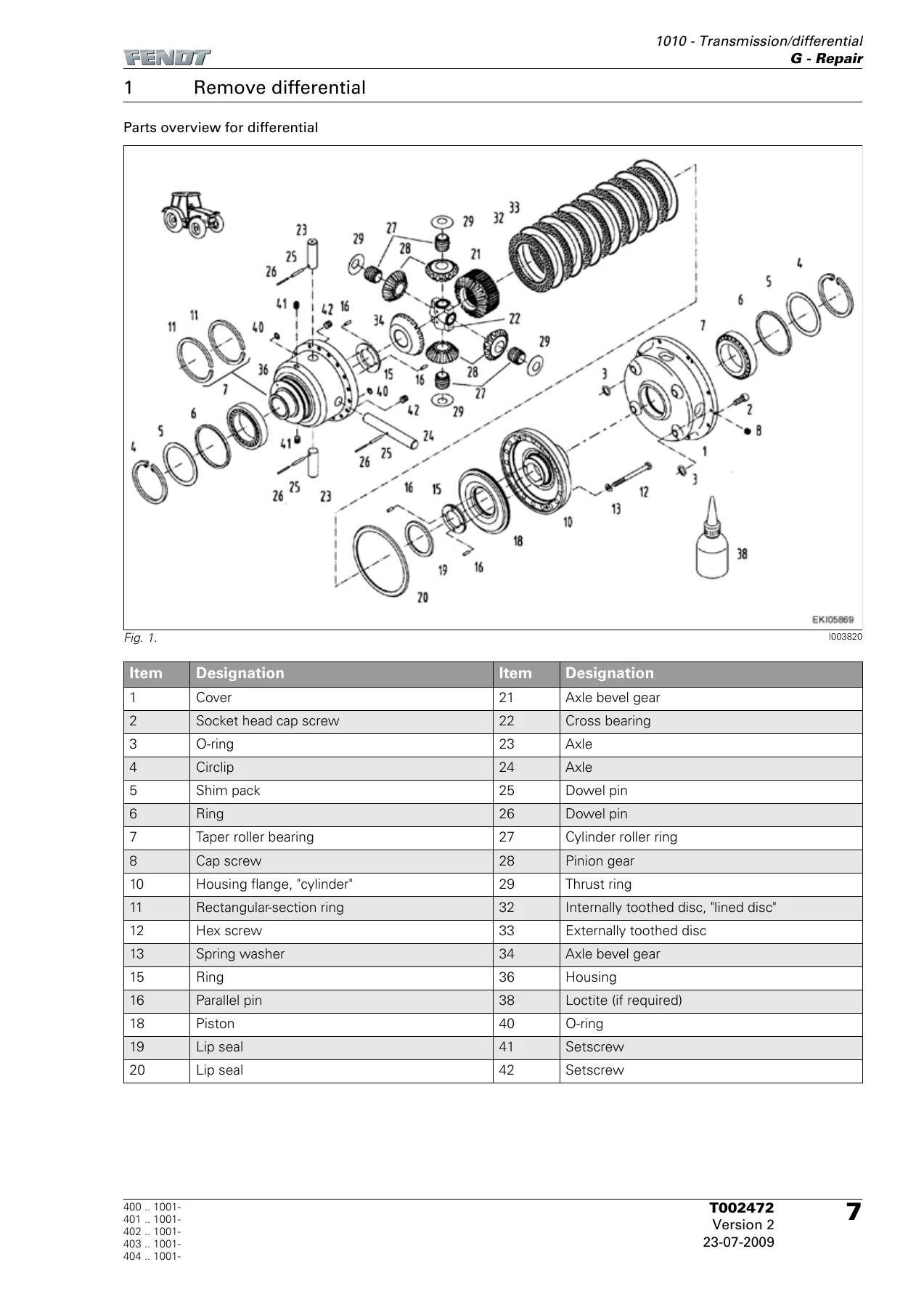
Owners of a Fendt 400 Vario COM III who do their own servicing will find the calibration steps, the fluid specification and change intervals, the fault code tables and the tightening torques. Workshop technicians and agricultural mechanics get the full disassembly and reassembly sequences for the differential, pinion shaft, axle drive, rear wheel brake, wheel brake cylinder, front PTO clutch and live PTO transmission, together with the settings and shim calculations those jobs need. Anyone running a fleet with serial-numbered 400 Vario COM III tractors can search the fault table by code and go straight to the register that fixes it.
Delivery
IMAGES PREVIEW
The manual is supplied as a PDF that can be opened on a workshop laptop, tablet or phone, and pages can be printed for use at the machine. There is no shipping and no waiting – the file is available for instant download after checkout. Keep it on the service vehicle alongside the tractor and it becomes the reference you reach for every time a fault code appears on the multifunction display or a transmission pressure reading looks wrong.

Reviews
There are no reviews yet.