

Deutz-Fahr Agrofarm 85 100 Workshop Manual PDF – Complete Service & Repair Guide
Original price was: $52.95.$34.95Current price is: $34.95.
The complete Deutz-Fahr Agrofarm 85 & 100 Workshop Manual in PDF. Covers engine, transmission, hydraulics, axles, electrics and wiring diagrams for all Agrofarm 85 and 100 variants including 5001-and-up serial ranges. Instant download, printable, works on any device.
Description
Deutz-Fahr Agrofarm 85 & 100 Workshop Manual – Complete PDF Service Guide
This is the full Deutz-Fahr Agrofarm 85 and Agrofarm 100 Workshop Manual, the same comprehensive service and repair documentation used by professional technicians to maintain, diagnose and overhaul these tractors. It covers all variants including the Agrofarm 85 -> 5001 and Agrofarm 100 -> 5001 serial ranges, with detailed procedures for the engine, transmission, front and rear axles, hydraulic system, electrical system, cab, bodywork and all major assemblies. Whether you are servicing a single tractor or running a repair workshop, this Agrofarm 85 100 workshop manual gives you the specifications, tightening torques, adjustment data and step-by-step instructions needed to do the job correctly.
File Details
- Manual Type: Workshop Manual
- Brand: Deutz-Fahr
- Models Covered: Agrofarm 85, Agrofarm 85 -> 5001, Agrofarm 100, Agrofarm 100 -> 5001
- Engines: BF4M 2012, BF4M 2012 C, BF6M 2012 C
- Publication Number: 307.W.0030.en.6.04
- Date of Issue: 09/2014
- Language: English
- Page Count: 1186
- File Format: PDF
Chapters Covered
- 0 – Introduction
- 10 – Technical Characteristics
- 20 – Calibrations and Electronic Diagnosis
- 30 – Method of Intervention
- 40 – Wiring Diagrams
0 – Introduction
The opening chapter provides essential safety notes, general safety rules, precautions for removal and refitting operations, lifting instructions, tightening torques for bolts, nuts, fittings and plugs, threadlockers, adhesives, sealants and lubricants, and conversion factors. This section sets the standard for safe working practices across all repair tasks on the Agrofarm 85 and 100.
10 – Technical Characteristics
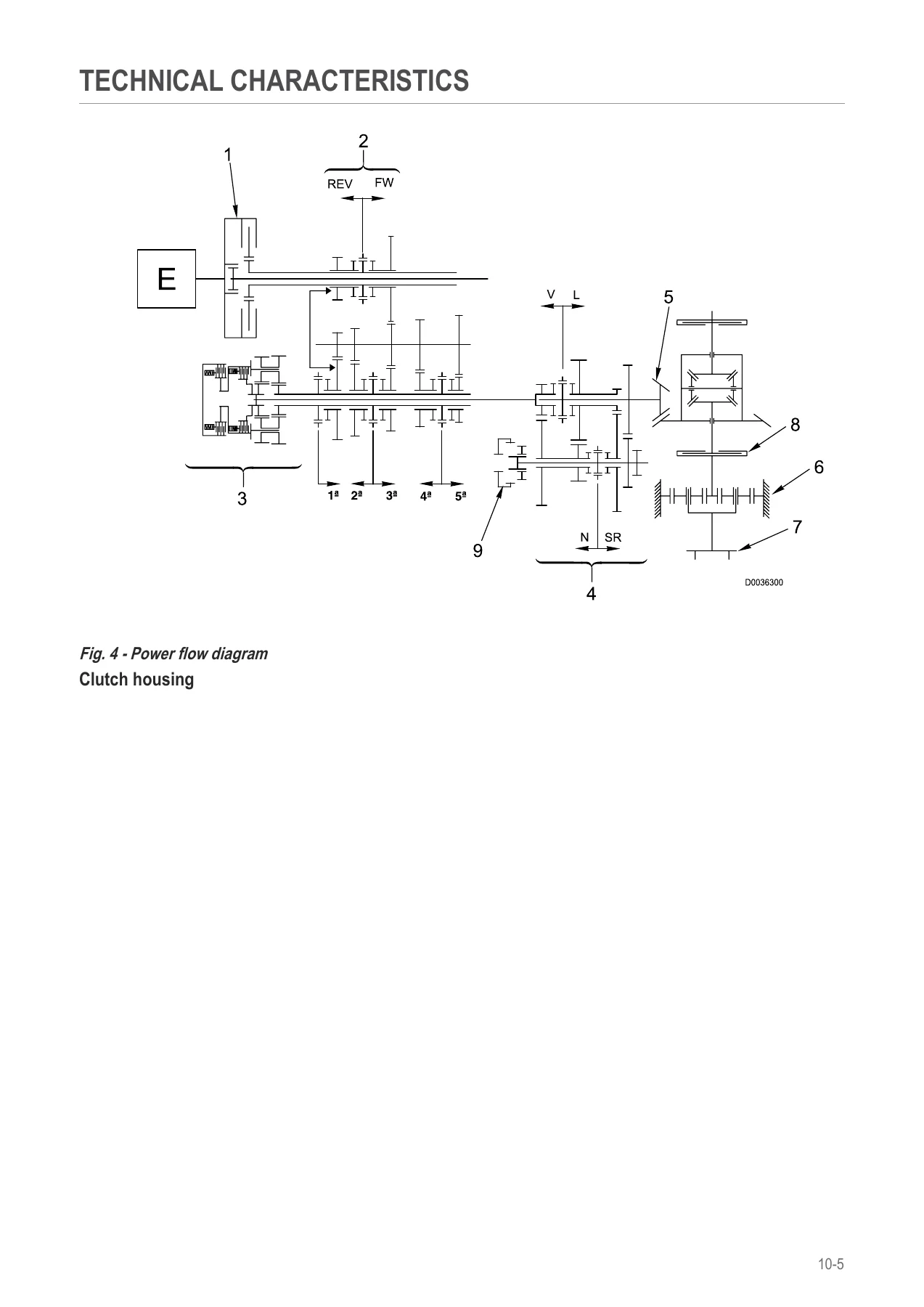
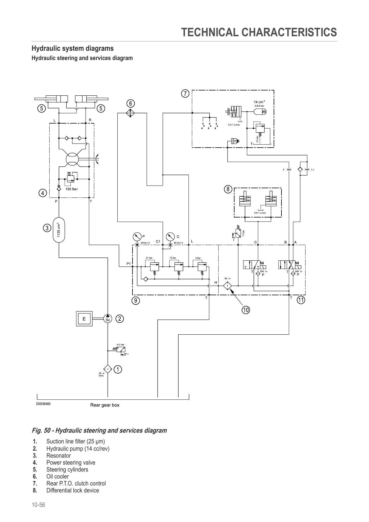
This chapter delivers the full technical data for the Agrofarm 85 and Agrofarm 100. Engine specifications cover the BF4M 2012, BF4M 2012 C and BF6M 2012 C engines, including bore, stroke, swept volume, compression ratio, firing order, valve timing, oil pressure and rated speeds. Transmission data is broken down by model and serial range, covering the 20 FWD + 20 REV synchronised gearbox, Hi-Lo unit, shuttle, rear P.T.O. options (2-speed 540/1000, 4-speed 540/540E/1000/1000E and Groundspeed), front axle, hydraulic system circuits, steering, braking system, trailer braking valve, services solenoid valves and shuttle solenoid valves. Wiring diagram references are also included.
20 – Calibrations and Electronic Diagnosis
This section covers diagnostic tools including the All Round Tester (ART) and SDF Analyser, their connection to the tractor, display language selection, serial port configuration, and the full menu structure for monitors, parameters, calibrations, alarms and tests. It also details the tractor’s electronic system, including the instrument panel and preheating system, shuttle ECU, commissioning and calibrating procedures for the Agrofarm 100, Agrofarm 85, and the 5001-and-up variants, clutch pedal calibration, and a comprehensive list of ECU alarms for the hydraulic shuttle, instrument panel, transmission and CANBUS. This chapter is essential for diagnosing electrical and electronic faults accurately.
30 – Method of Intervention
The largest chapter of the manual provides the complete method of intervention for every major assembly. It begins with B0 – Engine, covering engine separation from the transmission, dismantling, re-assembly, compression testing, front cover removal and repair, crankcase repair, mass balancing shaft repair, crankshaft checking, flywheel removal and repair, piston and connecting rod repair, camshaft checking, gearcase checking, valve clearance adjustment, rocker arm bracket checking, cylinder head checking, hydraulic pump drive repair, injection pump removal and re-installation, determining commencement of delivery, injector checking and control rod repair. C0 – Engine Accessories follows with coolant changing, radiator removal (with and without front PTO), fuel tank, fuel cooler, starter motor, silencer, exhaust pipe, air compressor repair, and thermostat removal and testing. D0 – Transmission covers changing transmission oil, range selector assembly, clutch plate and thrust bearing, clutch housing, front gearbox separation, shuttle assembly, gearbox and Hi-Lo unit, primary and secondary shaft disassembly for all variants, gearbox and shuttle complete unit, range gearbox and differential assembly, complete gearbox assembly, front gearbox oil seal, gearbox support and selector rods, differential and bevel gear pair adjustment, rear pinion disassembly, 4WD output shaft, PTO clutch, pump drive PTO, PTO output shafts, Groundspeed PTO, parking brake, and 4WD engagement device. E0 – Rear Axle covers RH and LH rear axle removal and disassembly, planet carrier, rear differential, brake discs and brake piston for all variants. F0 – Front Axle covers front pivot bracket, 4WD front axle, end float adjustment, steering cylinders, steering knuckle housing and axle shaft, differential unit and adjustment, bevel gear pair disassembly and adjustment, 4WD shaft, planetary reduction gear, front brake discs and front axle brake piston. G0 – Bodywork, Cab and Platform covers cab removal for both standard and 5001-and-up variants, front hood and side panels, cab access steps, fenders, front instrument panel, right and left-hand consoles, heating and air conditioning assembly, air conditioning controls, compressor, condenser, receiver drier, evaporator, heater matrix, expansion valve, antifreeze sensor, condenser cooling fans, condenser fan control pressure switch, clutch master cylinder, clutch piston, clutch control circuit, brake master cylinders, control lever adjustment, rear lift control lever adjustment, and remote valve control cables. H0 – Hydraulic System covers the pump for hydraulic lift and auxiliary services, power steering removal and disassembly, pressure relief valve setting, power steering pump, gearbox oil coolers, rear remote control valve, bleeding the braking circuit, services solenoid valve assembly, and shuttle solenoid valves assembly. L0 – Electrical System covers battery, alternator, clutch pedal potentiometer, shuttle output speed sensor, steering column switch, and shuttle ECU and forward/reverse selector. M0 – Front PTO covers front PTO removal, PTO assembly, pump assembly, clutch-brake assembly and solenoid valve assembly. N0 – Front Lift covers front lift removal and disassembly of front lift cylinders. R0 – Rear Lift covers lift complete assembly removal and disassembly for both model ranges, lift cylinder, bushes, auxiliary lift cylinders, hydraulic lift control valve, mechanical draft sensor for both model ranges, and 3-point linkage. S0 – Wheels covers front and rear wheel removal. V0 – Ballast and Towing Hitches covers towing hitch slide removal for both model ranges.
40 – Wiring Diagrams
This chapter provides the complete electrical wiring documentation for the Agrofarm 85 and 100. It includes an introduction to the structure of the unit, wiring and components index, basic electronics for mechanics, electrical and electronic components, component layouts, systems diagrams, earthing points, starting and preheating circuits, steering column switch lights for cab and platform versions, diagnostic accessories for standard and high-visibility cabs, instrument panel wiring, work lights, windscreen wipers, heating, A/C system, transmission, PTO, brakes and CAN BUS. The wiring harnesses section covers hood lights, engine wiring for front and lateral battery versions, battery wiring, preheating wiring, power supply wiring, instrument panel wiring, RH and LH drivetrain wiring, drivetrain shuttle wiring, cab shuttle wiring, cab power supply wiring, roof wiring, heating wiring, air conditioning wiring, condenser fan wiring, work lights wiring, windscreen wiper wiring, loudspeaker wiring, front lights wiring, rotating beacon wiring and trailer hydraulic braking wiring.
Why This Deutz-Fahr Agrofarm 85 100 Workshop Manual Is Essential
This Agrofarm 85 100 repair manual gives you the complete factory-derived procedures, specifications and diagnostic routines needed to service, repair and maintain these tractors correctly. With 1186 pages of detailed technical content, it covers everything from routine maintenance to complete engine and transmission overhauls. The step-by-step instructions are supported by hundreds of illustrations, exploded views, hydraulic schematics and wiring diagrams, making even complex repairs manageable. Whether you are a professional technician, a workshop owner or a tractor owner who prefers to do their own maintenance, this Deutz-Fahr Agrofarm 85 and 100 workshop manual provides the reliable information you need to keep your machine running at its best.
Stop guessing at torque values, adjustment clearances or wiring connections. This manual gives you the exact figures and procedures for your Agrofarm 85 or 100, helping you avoid costly mistakes and downtime. From engine compression testing to bevel gear pair adjustment, from clutch calibration to CANBUS diagnostics, every critical procedure is documented. The wiring diagrams alone are worth the investment, covering every circuit on the tractor including starting, preheating, lights, work lights, wipers, heating, air conditioning and the complete CANBUS network. With this level of detail, you can troubleshoot electrical faults methodically instead of replacing parts by trial and error.
IMAGES PREVIEW
Delivered as an instant PDF download, this Deutz-Fahr Agrofarm 85 100 workshop manual is available immediately after payment, with no shipping costs and no waiting for a physical book. You can view it on any device – laptop, tablet or smartphone – and print whichever pages you need for the workshop. Whether you are working on a single repair or managing a fleet, having the complete workshop manual at your fingertips ensures you always have the right information when you need it. The searchable PDF format lets you jump directly to the section you need, saving time and keeping your focus on the job.

Reviews
There are no reviews yet.