
Kubota Tractor Mechanism Workshop Manual 9Y011-18201 June 2006 PDF
Original price was: $32.95.$18.95Current price is: $18.95.
390-page Kubota Tractor Mechanism WSM (Code No. 9Y011-18201) explaining clutch, transmission, axle, brake, steering, hydraulic, electrical, and cabin structures used across B, L, and M series tractors. Training-style mechanism reference dated October 2001 / KISC issued June 2006.
Description
Kubota Tractor Mechanism Workshop Manual 9Y011-18201 June 2006 PDF
This Kubota Tractor Mechanism Workshop Manual 9Y011-18201 June 2006 PDF is the reedited Tractor WSM Mechanism book used to train servicing personnel on how Kubota tractor systems are built and how they work. It describes functions and structures found on existing Kubota tractors rather than walking one serial-numbered machine through a tear-down sequence. Model-specific transmission cross sections, full hydraulic-circuit schematics, and complete electrical wiring diagrams belong in each tractor’s own workshop manual; this book is the shared mechanism layer that those model manuals assume you already understand.
The engine chapter is not in this file. Diesel engine mechanism is covered in a separate workshop manual (Code No. 9Y021-01873 or 97897-60812 CD-ROM version). Parts numbers printed here are for identification inside the text and illustrations only — the notice page states they must not be used to order spare parts.
File Details
- Manual type: Workshop Manual (WSM) — Tractor Mechanism
- Brand: Kubota
- Document / code number: 9Y011-18201
- Copyright / reader date: October 2001, © KUBOTA Corporation 2001
- Issue marking: KISC issued 06, 2006 A; printed in Japan 2006.06 / 2001.10
- Language: English
- Page count: 390
- File format: PDF
Who This Book Is For
The To the Reader page states the purpose plainly: train servicing personnel so they can understand and service Kubota machines with speed, and give a trained mechanic a single place to refresh how the mechanisms work. Illustrations and text reflect product information current at publication, with Kubota reserving the right to change data without notice. If you already own a model workshop manual and keep hitting “how does this shuttle valve / HST / GST pack actually function,” this is the companion that explains the hardware families by type and code number.
Chapters Covered
- 1 Engine — chapter reserved only; content referred out to the diesel engine mechanism workshop manual
- 2 Clutch — dry type single plate clutch; dry type dual stage clutch (travelling and PTO); hydraulic multiple disc clutch Type 1 (travelling) and Type 2 (PTO)
- 3 Transmission — sliding mesh, constant mesh, and synchronous mesh gears; hydraulic shuttle shift and shuttle valves Type 1 (3A691-23800, 3A051-23803) and Type 2 (YW119-0103); swing shift; dual speed section and dual speed valve YW217-00100; hydrostatic transmissions Type 1 through Type 5 (codes 6C150-11603, TA240-58004, 6C200-11604, TD020-59992 / TD060-59994, TC220-59990) with oil flow, valves, operation, control linkage, and cruise control where fitted; Glide Shift Transmission Type 1 and Type 2; power shift system (electric and hydraulic components, auto speed control, power shift valve); differential gear system and differential lock; final reduction; PTO systems (rear and mid, live and ground, independent, fixed and interchangeable shafts, one-way clutch)
- 4 Rear Axle — hexagonal shaft type, flange type, flange type with dropped axle case
- 5 Brakes — travelling (foot) brake mechanical and hydraulic types (linkage, brake body, master cylinder, equalizer, brake oil); parking brake; hydraulic trailer brake and trailer brake valve 33963-69113
- 6 Front Axle — two-wheel drive; standard four-wheel drive; four-wheel drive with bi-speed turn (front-axle type and transmission types 1 and 2, including 4WD / bi-speed valves YW273-00100 and YW255-00102)
- 7 Steering — manual steering linkage and gear box; integral power steering Types 1 and 2; full hydrostatic Types 1–4 with hydraulic circuits, pumps, steering controllers, oil flow, and flow control / relief; steering cylinder
- 8 Hydraulic System — circuit symbols; hydraulic pump; oil strainer and filter; flow priority valves; regulator valves; relief valves (direct acting and pilot operated); three-point hitch (manual, position-control Types 1–10, draft control, solenoid proportional control, feedback linkages, load sensing, hydraulic cylinder, cylinder safety valve, lowering speed adjusting valve); auxiliary / remote control valves (double acting, single/double acting, floating with detent, self-cancelling with detent); flow control valve
- 9 Electrical System — starting system (main switch types, starter, starter relay, glow control, safety switch, engine stop solenoid, operator presence control types); charging system (AC dynamo, alternators with IC regulator, regulator); lighting system (combination, hazard, position, brake, Easy Checker lamps and sensors, trailer socket, cabin room lamp); gauges (fuel quantity, coolant temperature)
- 10 Cabin — air conditioning principles, layout, compressor / condenser / receiver / A/C unit, system control Types 1–3; front and rear windshield wipers and window washer
- 11 Others — quick-reference tables of hydraulic-related parts, electrical-related parts, and cabin components by model and code number
Taken together, the Kubota Tractor Mechanism Workshop Manual 9Y011-18201 June 2006 PDF gives a technician a typed catalog of how Kubota clutches engage and release, how shuttle and HST oil is modulated, how GST and power-shift electronics and hydraulics talk to each other, and how brakes, axles, steering, three-point hitch, remotes, starting/charging, and cabin A/C are put together. It is mechanism and oil-flow explanation first, not a substitute for the model book’s service limits, wiring diagrams, or overhaul steps.
Systems Explained in Depth
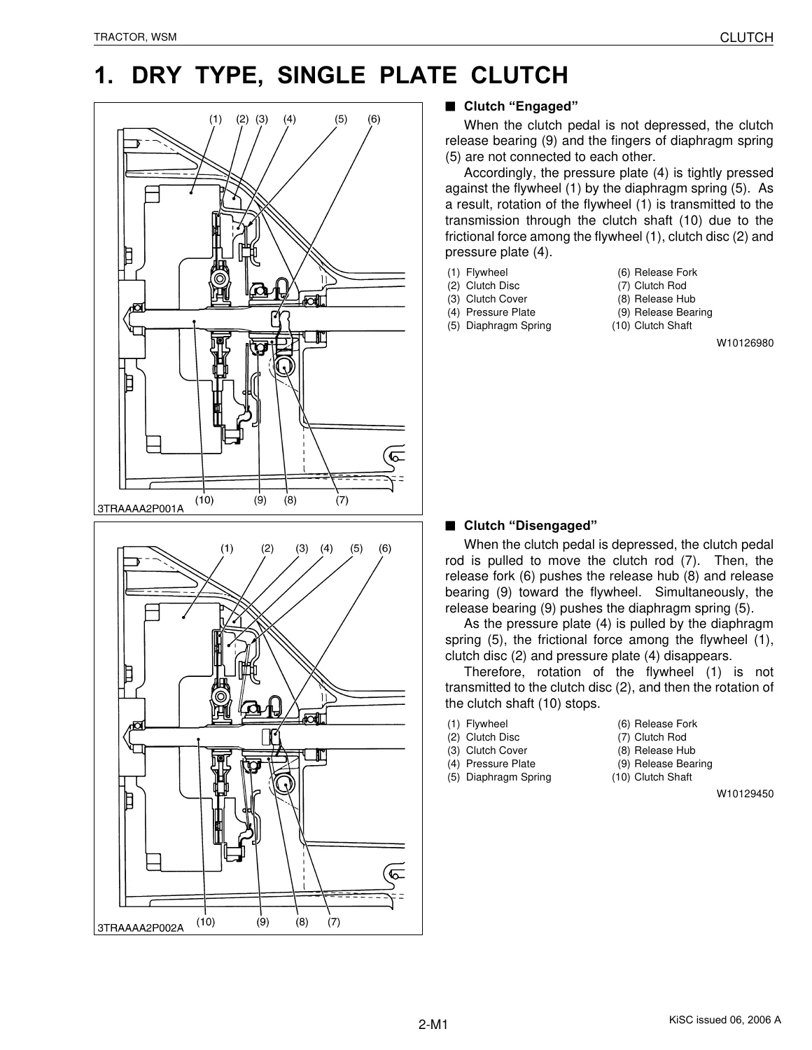
Clutch pages walk dry single-plate engagement and disengagement through the flywheel, disc, pressure plate, diaphragm spring, and release bearing, then dual-stage travelling/PTO clutch behavior at mid-stroke versus full stroke. Hydraulic multiple-disc packs are split into a travelling forward/reverse pack and a PTO pack that applies a brake plate to kill shaft drag when oil is dumped.
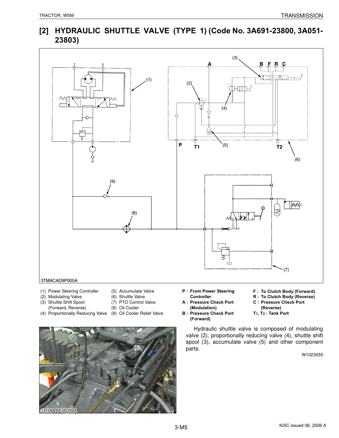
Transmission coverage is the largest block. Sliding, constant-mesh, and single- or double-cone synchronizer layouts sit in front of hydraulic shuttle power paths (forward through the 28T gear, reverse through the idle-gear train). Shuttle valve Type 1 and Type 2 pages show modulating, proportionally reducing, and accumulate valves, plus what happens with the shuttle lever in Neutral, Forward, or Reverse and with the clutch pedal depressed. Five HST types are treated separately by unit code, each with structure, oil flow, valves, pedal linkage, and cruise-control release off the brake pedal where that hardware exists. GST Type 1 breaks out regulator, rotary valve, shift pistons, check and low-pass valves, modulating valves, accumulator, clutch valve, and clutch pack. GST Type 2 and the power-shift chapter add electrical control, travel/field auto speed modes, downhill / clutch-pedal / shuttle / auxiliary interlocks, and the power-shift valve.
Downstream of the gearbox the book covers dog-clutch, pin, and hydraulically actuated differential locks; planetary final reduction; live, ground, independent, mid, and rear PTO arrangements; and one-way clutches that brake a spinning PTO when the source of power stops. Rear axle construction is shown as hexagonal-shaft, flange, and dropped-case flange designs. Front axle pages contrast 2WD knuckle construction with standard 4WD and bi-speed-turn hardware in the axle or in the transmission case, including solenoid oil flow at a stated clutch hold pressure of 18.5 kg.
Brake mechanism includes independent mechanical wet discs, a hydraulic wet-disc circuit with master cylinder and equalizer (piston stroke approx. 4 mm / 0.16 in., oil displacement approx. 1.2 to 1.3 cm³, pedal-stroke difference less than 5 mm / 0.20 in.), and a trailer brake valve that proportions trailer line pressure to the tractor service-brake line. Steering runs from a manual gearbox through integral units and several full-hydrostatic controllers to a double-acting, both-rod steering cylinder laid parallel to the front axle.
IMAGES PREVIEW
Hydraulic-system pages start with circuit symbols and the pump / strainer / filter / priority / regulator / relief stack, then spend the bulk of the chapter on three-point position and draft control valve families (ten numbered position-control valve codes), feedback linkages, top-link and lower-link load sensing, cylinder safety and lowering-speed valves, and a long set of remote-valve types (mechanical check, floating detent, self-cancelling detent, single/double acting). Electrical pages document main-switch terminal maps, OPC seat-switch logic for ROPS and cabin, Easy Checker lamp inputs, trailer-socket pin functions, and coolant-temperature thermistor resistance tables for three sensor codes. Cabin pages close with refrigeration-cycle theory, compressor-to-evaporator layout, three control types, wiper motors/switches, and a 2.0 L (2.1 U.S. qts., 1.8 Imp. qts.) washer tank.
Model Reference Tables in Chapter 11
Chapter 11 does not add new theory. It lists hydraulic, electrical, and cabin component names and code numbers against two model groups so you can jump from a tractor in the shop to the matching mechanism type in chapters 2–10.
Table 1 models: B1410, B1610, B1710, B2110, B2410, B2710, B2910, B7400, B7500; ST α-30, ST α-35, L2600, L2500, L3000, L4300, L3010 (L2900), L3410 (L3300), L3300CAB, L3710 (L3600), L3710CAB, L4310 (L4200), L4310CAB, L4610, L4610CAB; M4900, M4900CAB, M5700, M5700CAB, M6800, M6800CAB, M8200, M8200CAB, M9000, M9000CAB, M110, M120.
Table 2 models: B7410, B7510, B7610, B7800, B2630, B3030, B3030CAB; L2800, L3400, L4400, L3130, L3430, L3430CAB, L3830, L4330, L4330CAB, L4630, L4630CAB, L5030, L5030CAB, STV32, STV36, STV40; MX5000, M4800, M5700HD, M5700HDCAB, M6800HD, M6800HDCAB, M8200HD, M8200HDCAB, M9000HD, M9000HDCAB, ME5700, ME5700CAB, ME8200, ME8200CAB, ME9000, ME9000CAB, M95S, M105S, M95X, M105X, M125X.
Those lists are the models named in this Kubota Tractor Mechanism Workshop Manual 9Y011-18201 June 2006 PDF. Dual-speed text also names M95S-DS and M105S-DS as tractors that carry the dual-speed device as standard equipment. Always pair this mechanism book with the workshop manual for the exact tractor when you need that machine’s circuit drawings or service specifications.
Get the Manual and Use It on the Machine
With the Kubota Tractor Mechanism Workshop Manual 9Y011-18201 June 2006 PDF you can trace why a dual-stage clutch drops travel first and PTO second, how a shuttle valve modulates F/R oil when the pedal is down, which HST or GST valve family you are looking at by code number, how bi-speed and 4WD clutches are fed, how wet-disc and trailer brakes share pressure, and how position-control, remote, starting, OPC, and cabin A/C hardware are arranged. Using the published oil-flow paths, valve functions, and construction views keeps diagnosis aligned with the way Kubota built the mechanism instead of guessing from a single model drawing.
After payment the file is delivered as an instant PDF download — no shipping wait, readable on computer, tablet, or phone, and printable for the bench or toolbox. Keep the model workshop manual beside it for serial-specific specs and circuits; use this WSM Mechanism volume for the shared clutch, transmission, axle, brake, steering, hydraulic, electrical, and cabin structures those model books expect you to know.
Reviews
There are no reviews yet.