
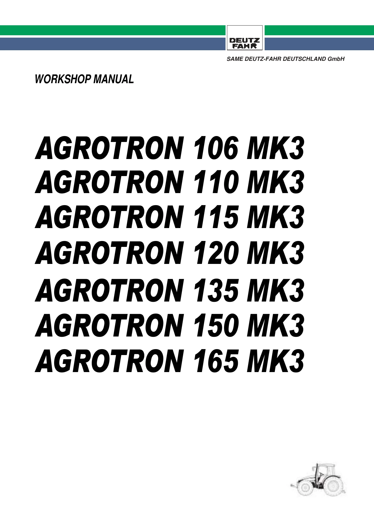
Deutz-Fahr Agrotron 106-165 MK3 Workshop Manual – Repair, Hydraulics & Diagnostics PDF
Original price was: $34.95.$19.95Current price is: $19.95.
Complete Deutz-Fahr Agrotron 106-165 MK3 workshop manual covering transmission, rear axle, rear PTO, brakes, front axle, hydraulic suspension, the full hydraulic system and the SERDIA/EDS diagnostic software documentation. English, 1,018-page PDF for the 106, 110, 115, 120, 135, 150 and 165 MK3 tractors.
Description
Deutz-Fahr Agrotron 106-165 MK3 Workshop Manual – Complete Repair, Hydraulics & Diagnostics Guide
This Deutz-Fahr Agrotron 106-165 MK3 Workshop Manual is the full repair, overhaul and diagnostic reference for the seven-model MK3 Agrotron range: 106 MK3, 110 MK3, 115 MK3, 120 MK3, 135 MK3, 150 MK3 and 165 MK3. It was written for repair technicians in authorised service centres, and it sets out the correct methods for fault diagnosis, safe working, dimensional checks and visual inspection, together with the products to use, the tightening torques and the adjustment data for each job. Whether you are rebuilding a rear axle, tracing a hydraulic fault through the Load Sensing circuit or connecting diagnostic software to the transmission ECU, this Agrotron MK3 workshop manual is the document the work is meant to be carried out from.
File Details
- Manual type: Workshop / service and repair manual
- Brand: Deutz-Fahr
- Models covered: Agrotron 106 MK3, 110 MK3, 115 MK3, 120 MK3, 135 MK3, 150 MK3, 165 MK3
- Section structure: Section 00 General, Section 10 Technical Descriptions, Section 20 Software and Diagnostics, Section 30 Checks and Adjustments, Section 40 Electrical and Electronic Systems
- Language: English
- Page count: 1,018 pages (page index)
- File format: PDF
Chapters Covered
- Section 00 – General: general safety rules, how the manual is structured and updated, symbols used in the manual, products required (threadlockers, degreasers, instant adhesives, silicone and polyurethane sealants, retaining compounds, lubricants), special tools, conversion factors and standard tightening torques
- Section 10 – Technical Descriptions: mechanical and hydraulic operation of machine components, designations of the various components, hydraulic diagrams and general technical data
- Section 20 – Software and Diagnostics: SERDIA engine ECU software operator’s manual, EDS Electronic Diagnosis System, Power-Shift diagnosis with DEST 38, Power-Shuttle diagnosis with DEST 45, Agrotronic-HD and ASM, Infocenter diagnosis, and spring-suspended front axle diagnosis
- Section 30 – Checks and Adjustments: methods, checks and adjustments on external components that do not require removal of the tractor frame and cab assemblies
- Section 40 – Electrical and Electronic Systems: information and diagrams for the machine’s electrical and electronic systems
- 1. Transmission
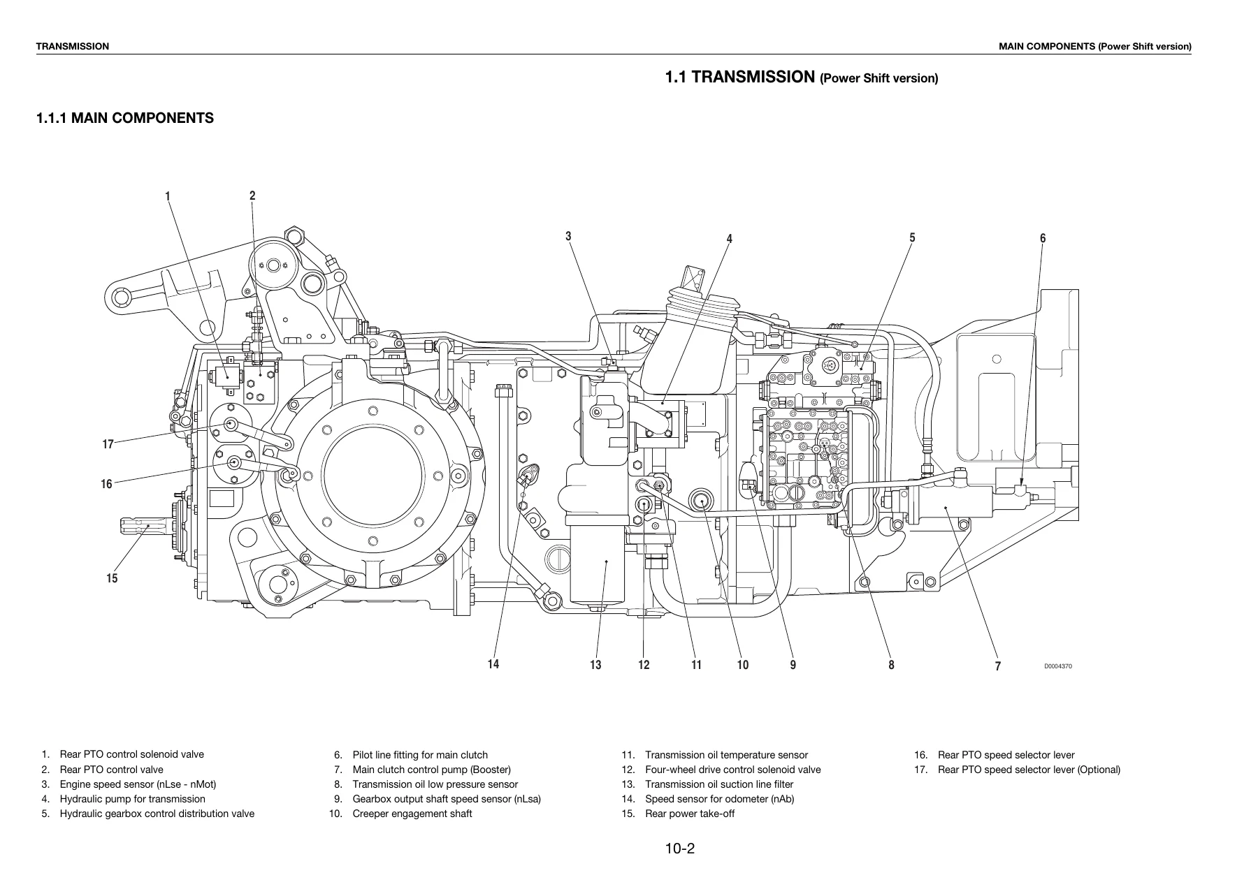
- 1.1 Transmission (Power Shift version): main components, transmission hydraulic system, gearbox and gearbox components, main clutch, hydraulic gearbox and shuttle distribution valve, clutch engagement and solenoid valve operation schematic, transmission electronic system schematic
- 1.2 Transmission (Power Shuttle version): main components, transmission hydraulic system, gearbox and gearbox components, main clutch, hydraulic gearbox and shuttle distribution valve, clutch engagement and solenoid valve operation schematic, transmission electronic system schematic
- 1.3 Rear axle
- 1.4 Rear PTO
- 2. Braking System
- 2.1 Brake master cylinder
- 2.2 Brake
- 2.3 Trailer braking system: hydraulic trailer braking (Italy version and Export version), air trailer braking (Italy version and Export version)
- Compressor, pressure limiting valve, cab suspension feed valve, trailer braking valve (2-way) and trailer braking valve (1-way)
- 3. Hydraulic Front Axle Suspension
- 3.1 Front suspension control valve
- 4. Front Axle
- 4.1 Hub carrier and final reduction unit
- 4.2 Differential (100% hydraulic locking and 45% self-locking versions)
- 5. Hydraulic System
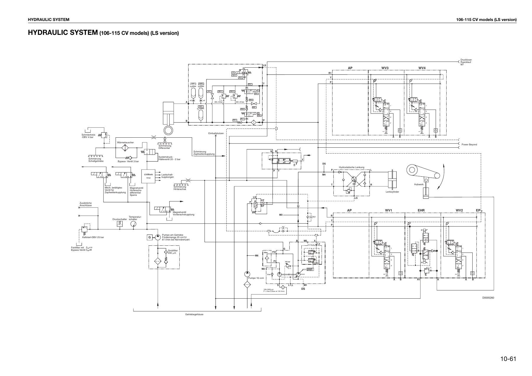
- Hydraulic system schematics for 106-115 CV and 120-165 CV models in both CCLS and LS versions
- 5.1 Variable displacement pump, 5.1.1 Boost pump, 5.1.2 Hydraulic pump, 5.1.3 Load Sensing valve and pressure cut-off valve
- 5.2 Hydraulic services gear pump (106-115 CV models), 5.3 Steering gear pump (106-115 CV models), 5.4 Gear pump for hydraulic services and steering (120-165 CV models)
- 5.5 Priority valve, 5.6 Auxiliary services control valve
- 5.6.1 to 5.6.6 Control valve types, services control section, component descriptions, inlet manifold (CC version) and lift control valve section
Taken as a whole, this Agrotron MK3 workshop manual is built around the actual service life of the tractor rather than around a parts list. The transmission chapters explain how the hydraulically controlled 8-speed gearbox, the creeper unit, the main clutch and the 6-speed mechanical gearbox sit together, and how the distribution valve pilots the S, H, M and L ratios and the forward/reverse shuttle. The brake and trailer braking chapters take the reader from the master cylinder through to the air braking circuit and the quick-action couplers. The front axle and suspension chapters deal with the hub carrier, final reduction unit, differential, kingpins, steering sensor and the accumulators that form the elastic elements of the hydraulic front axle suspension. The hydraulic system chapters then tie everything together with full circuit diagrams, pressure test points and sectional views of the variable displacement pump, the Load Sensing valve and the auxiliary services control valve.
Power Shift and Power Shuttle – Both Transmission Versions Covered
The manual treats the two transmission configurations of the Agrotron MK3 separately, which matters because they behave differently. In the Power Shift version a shuttle command is only implemented once tractor speed falls below 10 km/h and the operator depresses the clutch pedal; the main clutch is operated manually through a clutch pilot cylinder and a booster cylinder. In the Power Shuttle version the direction change is managed entirely by the electronic control unit through a proportional solenoid valve acting directly on the main clutch, with no clutch pedal input required. Each version has its own hydraulic schematic, its own distribution valve layout, its own solenoid valve operation tables for L-M-H-S and S-H-M-L shifting in forward and reverse, and its own electronic system schematic with the full pin assignment of the control unit.
Gearbox Control Valve Pressure Test Points and Hydraulic Diagnosis
One of the most practical parts of this Agrotron MK3 repair manual is the identification of the pressure test points on the gearbox control valve. Each test point is listed with its function and thread size (M10x1), covering A or F clutch pressure, B or G clutch pressure, Y3 or Y4 solenoid valve pressure, pressure Pg to the relief valve, pressure Pr from the relief valve at 18 bar, engagement pressure of clutch C or D, general pressure at 18 bar, engagement pressure of clutch A/B or F/G, pilot pressure at 10 bar, D clutch pressure, C clutch pressure and modulated pressure. The individual valves are also named and located: the breather valve, the clutch selection valves G1 and G2, the clutch engagement valves H1 and H2, the relief valve S1, the pilot solenoid valves Y1 to Y5, the pilot pressure regulating valve P3, the general pressure regulating valve P4, the road/field operating mode selection valve U, the pressure modulating valve P1, the 2-stage valve P2 and the null shift valve R1.
Hydraulic Pump and Load Sensing Coverage
For tractors fitted with the LS hydraulic system, the manual describes the variable displacement piston pump in detail: the swash plate, control piston, cylinder barrel, valve plate, pistons and piston shoes, the boost pump that supplies the pump and the transmission lubrication circuit, and the Load Sensing valve and pressure cut-off valve that regulate delivery according to demand. The four operating stages of the LS valve are explained, from the neutral position with the directional control valve closed, through operation of a control lever, stabilisation of the flow rate, and the saturation condition when the pump can no longer increase delivery. That is the level of explanation that lets a technician understand why a machine behaves as it does, not simply which bolt to remove.
Diagnostic Software Documentation Included
The software and diagnostics section covers the SERDIA program used to communicate with DEUTZ engine control units, including hardware and software requirements, ECU selection, measured values, parameters and configuration, error memory, function tests and extras such as maximum speed, logistics data and load spectrum. It also documents the EDS Electronic Diagnosis System, the Power-Shift diagnosis program DEST 38 and the Power-Shuttle diagnosis program DEST 45, with error code lists and descriptions, sensor and solenoid valve locations for the T-7100, T-7200 and T-7300 transmissions, Agrotronic-HD and ASM, Infocenter diagnosis, and diagnosis of the spring-suspended front axle. Error analysis guidance is included for each program.
What This Workshop Manual Lets You Do
With the Deutz-Fahr Agrotron 106-165 MK3 Workshop Manual to hand you can strip and rebuild the hydraulically controlled gearbox, set up the shuttle and range clutches, overhaul the rear axle differential and the epicyclic reduction units, service the wet brakes and the trailer braking valves, repair the hydraulic front axle suspension control valve, and rebuild the variable displacement pump complete with its Load Sensing and pressure cut-off valves. You can identify which clutch pack is at fault from the pressure test points rather than by trial and error, check the gearbox oil level indicators on the transmission and the rear reduction unit, and work through the correct sequence for removing and refitting assembled units using the special tools listed in Section 00.
Correct procedures and the specified tightening torques are what separate a repair that lasts from one that comes back. This manual gives the tightening torques determined by the manufacturer, the adjustment data, the products to use on each joint and thread, and the safety precautions that apply before pressure is discharged from a circuit or a component is lifted. Following them protects the machine and protects the person working on it.
IMAGES PREVIEW
Delivery is instant. The Deutz-Fahr Agrotron 106-165 MK3 workshop manual is supplied as a PDF that downloads immediately after payment, with no shipping and no waiting for a parcel. It opens on a workshop PC, a laptop or a tablet, and any page or diagram can be printed and taken to the machine. Note that this manual does not contain the engine and transmission sections – those are covered in separate Deutz publications, which are listed in the manual’s own introduction.
Reviews
There are no reviews yet.