★ TRUSTED BY 321,897+ PROFESSIONALS WORLDWIDE
🏒
Trusted Business
Verified & Licensed
πŸ›‘οΈ
Virus Free Files
100% Safe Downloads
πŸ”’
Secure Payment
SSL Protected
⚑
Instant Delivery
Available Immediately
Sale!

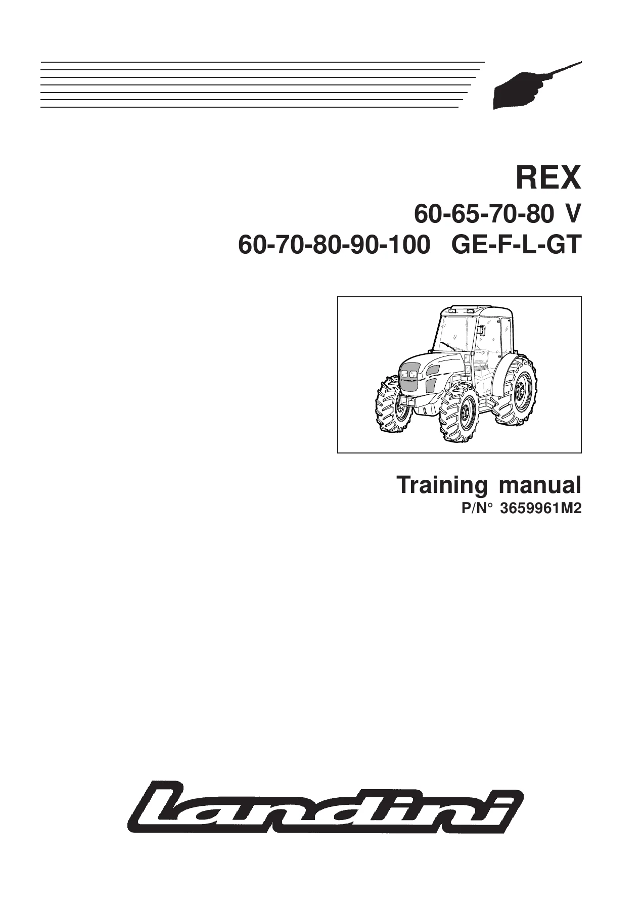
Landini Rex 60-100 V GE F L GT Tractor Training Manual 3659961M2 – PDF Download

Original price was: $39.95.Current price is: $22.95.

Landini Rex Orchard and Vineyard tractor training manual P/N 3659961M2 covering Rex 60, 65, 70, 80, 90 and 100 in V, GE, F, L and GT versions – engine timing, clutch, transmission, 4WD axle, PTO, low and high pressure hydraulics, mechanical and electronic power lift, full electrical wiring, air conditioning and special tools.

⚑
Instant PDF Download
Available immediately
πŸ’Ύ
Save to Your Device
Download & keep forever
πŸ›‘οΈ
Antivirus Scanned
100% virus-free
🌍
Trusted Worldwide
175,000+ customers

Description

Landini Rex 60-100 V GE F L GT Training Manual – P/N 3659961M2

This is the Landini training manual issued under part number 3659961M2 for the Rex Orchard and Rex Vineyard tractor families. It is the reference document used at the Landini training centre and covers the Rex Orchard 60 – 70 – 80 – 90 – 100 and Rex Vineyard 60V – 65V – 75V – 80V series in the V, GE, F, L and GT configurations. Rather than a simple operator booklet, it is a technical training volume: mechanical and hydraulic layouts, wiring diagrams, engine timing procedures, torque tables, adjustment values and disassembly/reassembly notes for the assemblies that require particular expertise or manufacturer recommendations.

File Details

  • Manual type: Technical training manual (service and repair reference)
  • Brand: Landini
  • Document number: P/N 3659961M2
  • Model families covered: Rex Orchard 60-70-80-90-100; Rex Vineyard 60V-65V-75V-80V
  • Configurations: V, GE, F, L, GT; 2WD and 4WD
  • Engines covered: Perkins 903.27, 903.27T, 1004.40, 1004.42, 1004.40T
  • Language: English
  • Format: PDF
  • Length: 710 pages

Chapters Covered

  • Chapter 1 – Introduction, identification and workshop basics
    • Reading the manual and how it is structured
    • Tractor identification (chassis, engine and cab serial numbers)
    • Weights, dimensions and general specifications
    • Engine, clutch, transmission, PTO, 2WD and 4WD axle and hydraulic specifications
    • Working in safety – accident prevention rules, danger decals, replacing tractor parts
    • Pre-delivery inspections and routine maintenance guide
    • Conversion tables – length, area, volume, weight, pressure, moment of rotation, temperature
    • Loctite sealant types and practical application advice
    • Driving torques and general assembly instructions for seals, O-rings and bearings
  • Chapter 2 – Technical specifications, torques and engine timing
    • Main technical specifications for Rex 60-65-70 and Rex 80-90-100
    • Standard and recommended driving torques
    • Recommended torques for engine 903.27 and for 1004.40 / 1004.42 / 1004.40T
    • 903.27 engine tuning – finding compression TDC of cylinder no. 1, camshaft timing, injection pump locking angle and injection pump timing
    • 1004.40 / 1004.42 / 1004.40T engine timing – TDC, camshaft timing and injection pump timing
  • Chapter 3 – Clutch
    • Assembly drawing and component identification
    • Description of operation of the twin-plate clutch
    • Technical specifications
    • Inspection, overhaul and lever height adjustment
    • Special tool 01 FRI REX
  • Chapter 4 – Transmission
    • General description of the modular transmission and the reverse shuttle, creeper, underdrive and overdrive options
    • Power train diagrams, tooth numbers and transmission configurations
    • Driving torques and sealants
    • Engine-gearbox axle assembly, gearbox, bevel gear pair and rear differential, side final drives
    • Pinion position adjustment, bearing preload and crown wheel backlash setting
    • Special tools 01 CMB REX, 01 DIF MYT, 01 DT REX, 02 DT REX, 03 DT REX, 04 DT REX
  • Chapter 5 – 4WD front axle
    • Final drive assembly drawing and parts
    • 4WD clutch Spring-on description of operation
    • Technical specifications and driving torques/sealants
    • Pinion-crown wheel adjustment and fork taper bearing adjustment
    • Special tools 01 DT REX, 02 DT REX, 03 DT REX, 05 DT REX, R 504
  • Chapter 6 – Power take-off
    • Assembly drawings for Rex 60-65-70-75-80 and Rex 90-100
    • Description of operation, 540/750 and 540/1000 RPM selection
    • Types of control, PTO engaging and speed selector levers
    • PTO speed sensor adjustment and inspection
    • Technical specifications and proportional PTO data
  • Chapter 7 – Low pressure hydraulic circuit
    • Circuit layout and description
    • Technical specifications of the pump, steering system and power clutch valve system
    • Hydraulic pump, power steering system and Orbitrol valve system
    • Power clutch control valve, operation phases C2.1 to C2.7
    • Solenoid valves, differential lock supply, PTO power clutch cylinder supply
    • 4WD clutch (Spring-on) oil supply
    • Checking operating pressure values and special tools
  • Chapter 8 – High pressure hydraulic circuit
    • Circuit description and technical specifications
    • Single and double gear pump
    • Trailer brake valve – Italian type and Export type, all operating phases
    • Auxiliary control valves for Rex Vineyard and Rex Orchard tractors
    • Flow divider, standard, floating, automatic release and hydraulic engine control valves
    • Electro-hydraulic flow selector
    • Mechanical and electronic power lift oil supply, lubrication circuit and 1.5 bar governor valve
    • Operating pressure tests and special tools
  • Chapter 9 – Mechanical power lift
    • Assembly drawing and main components
    • Operating modes – position, draft, mixed and float
    • Valve system components and operating phases
    • Technical specifications, driving torques and sealants
    • Hydraulic tests, power lift adjustments, operating pressure tests and troubleshooting
    • Special tools 01 IDR REX, CR 342, 122 IDR GL
  • Chapter 10 – Electronic power lift
    • Introduction and main components
    • Technical specifications and hydraulic circuit
    • Control valve system – neutral, lowering and lifting positions
    • Electrical system, wiring diagram, connectors, control console, electronic plant, external buttons and sensors
    • Shock absorber function
    • Functionality tests, check-control and troubleshooting, fault code tables
    • Hydraulic tests and special tools
  • Chapter 11 – Electrical system
    • Basic electrical concepts, electricity symbols and how to read a functional wiring diagram
    • Wiring layout and cable colour chart
    • Battery-starter motor line
    • Technical specifications and diagrams for Rex Orchard footstep and cab tractors, Rex Vineyard footstep and cab tractors, Europe and NAO versions
    • Relays, fuse holders, fuse functions and ampere ratings
    • Component identification tables and connector terminal matches

    Complete PDF Bookmark Tree

    Complete Bookmarks

    The complete bookmarks in the β€œLandini Rex 60-100 V GE F L GT Tractor Training Manual 3659961M2 – PDF Download” are as follows:

    REXp. 1
    CONTENTSp. 2
    Chap.1 INTRODUCTIONp. 4
    Sect. 1 Reading the manualp. 6
    1-1 Introductionp. 7
    1-2 Structure of the manualp. 7
    Sect. 2 Tractor identification and technical specificationsp. 8
    2-1 Tractor identificationp. 9
    2-2 Weights and dimensionsp. 10
    2-3 Engine specificationsp. 16
    2-4 Clutch specificationsp. 19
    2-5 Transmission specificationsp. 19
    2-6 Power take-off specificationsp. 26
    2-7 2 WD axlep. 27
    2-8 4 WD front axle specificationsp. 28
    2-9 Hydraulic circuit specificationsp. 29
    Sect. 3 Working in safetyp. 32
    3-1 Essential rules for accident preventionp. 33
    3-2 Danger decalsp. 39
    3-3 Replacing tractor partsp. 42
    3-4 Safe use of the tractorp. 42
    Sect. 4 Pre-delivery inspections and maintenancep. 44
    4-1 General informationp. 28
    4-2 Inspections before deliveryp. 45
    4-3 Routine maintenance guidep. 46
    Sect. 5 Conversion tablesp. 48
    5-1 Lengthp. 49
    5-2 Areap. 52
    5-3 Volumep. 53
    5-4 Weightp. 56
    5-5 Pressurep. 58
    5-6 Moment of rotationp. 60
    5-7 Temperaturep. 62
    Sect. 6 Sealantsp. 64
    6-1 Types of Loctite sealantsp. 65
    6-2 Practical advicep. 66
    Sect. 7 Driving torquesp. 68
    Sect. 7 Driving torquesp. 69
    Sect. 8 General assembly instructionsp. 70
    8-1 Sealsp. 71
    8-2 O-ringsp. 72
    8-3 Bearingsp. 73
    Chap.2 ENGINEp. 76
    Precautions and safety warningsp. 78
    Sect. 1 Technical specificationsp. 80
    1-1 Main technical specifications – Rex 60-65-70p. 81
    1-2 Main technical specifications – Rex 80-90-100p. 83
    Sect. 2 Driving torque valuesp. 86
    2-1 Standard driving torquesp. 87
    2-2 Recommended driving torques: engine 903.27p. 87
    2-3 Recommended driving torques: engine 1004.40/1004.42/1004.40Tp. 91
    Sect. 3 903.27 engine tuningp. 96
    3-1 Introductionp. 97
    3-2 How to find the compression TDC of cylinder NΒ° 1p. 98
    3-3 How to check camshaft timingp. 98
    3-4 How to check the injection pump locking anglep. 99
    3-5 How to check injection pump timingp. 100
    Sect. 4 1004.40 / 1004.42 / 1004.40T engine timingp. 102
    4-1 Introductionp. 103
    4-2 How to find the compression TDC of cylinder NΒ° 1p. 105
    4-3 How to check camshaft timingp. 106
    4-4 How to check injection pump timingp. 107
    Chap.3 CLUTCHp. 108
    Precautions and safety warningsp. 109
    Sect.1 General descriptionp. 110
    1-1 Drawing of assembly and componentsp. 111
    1-2 Description of operationp. 113
    Sect.2 Technical specifications.p. 114
    2-1 Main technical specificationsp. 115
    Sect.3 Inspection, overhaul and adjustmentp. 116
    3-1 Inspection and overhaulp. 117
    3-2 Adjustmentp. 118
    Sect.4 Special toolsp. 120
    Sect.4 Special toolsp. 121
    Chap.4 STANDARD TRANSMISSIONp. 122
    Precautions and safety warningsp. 123
    Sect.1 General descriptionp. 124
    1-1 Introductionp. 125
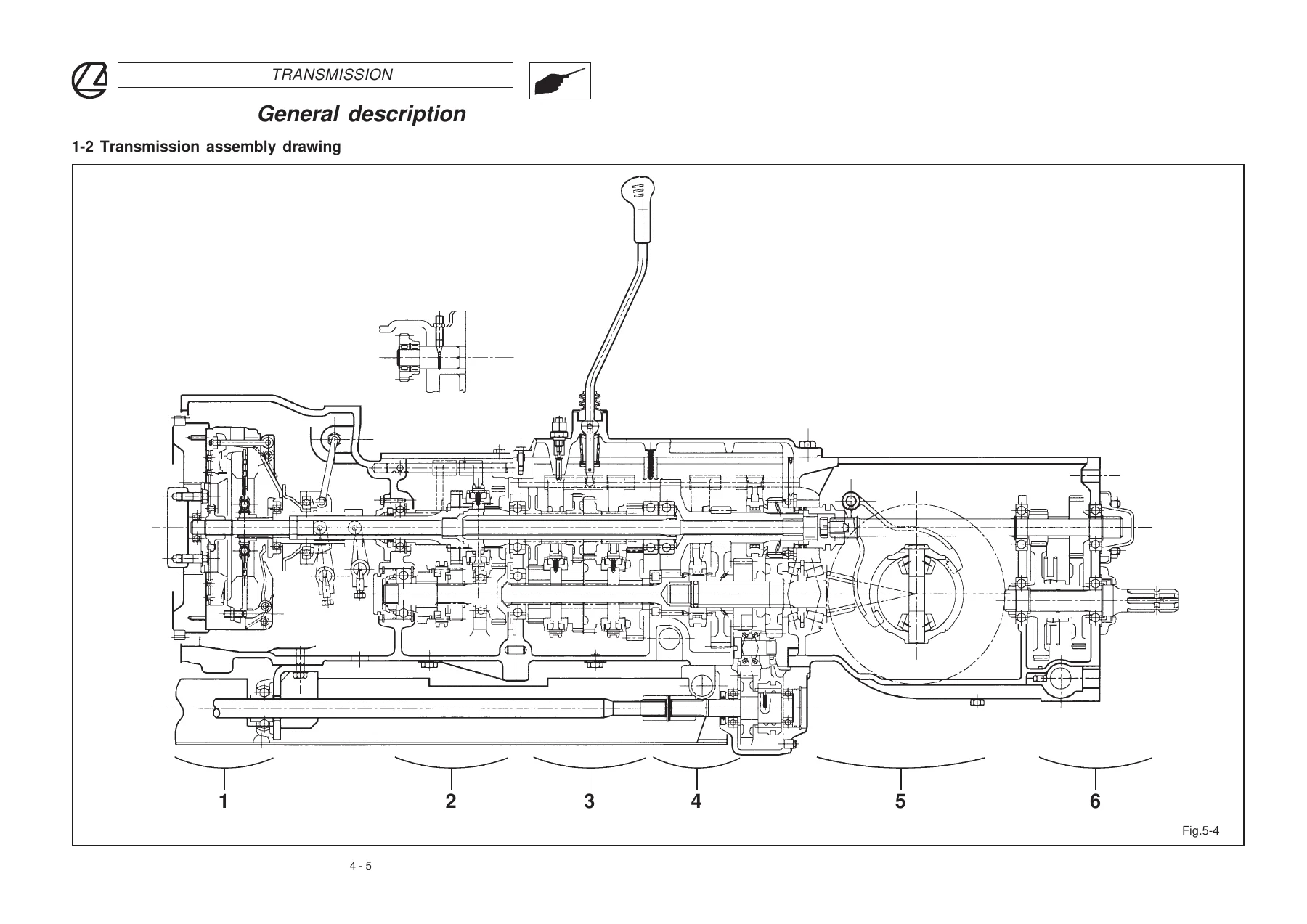
    1-2 Drawing of transmission assemblyp. 126
    Sect.2 Technical specificationsp. 128
    2-1 Main technical specificationsp. 129
    2-2 Power train diagramp. 130
    2-3 Driving torques and sealantsp. 132
    Sect.3 Main componentsp. 134
    A – Engine-gearbox axle assemblyp. 136
    A1 – Drawing of assembly and main componentsp. 137
    A2 – Description of operationp. 139
    A3 – Assembly drawings of the optionsp. 140
    A4 – Inspection and adjustmentp. 146
    B – Gearboxp. 148
    B1 – Assembly drawing and main componentsp. 149
    B2 – Description of operationp. 151
    B3 – Inspection and adjustmentp. 152
    C – Bevel gear pair and rear differentialp. 154
    C1 – Drawing of assembly and main componentsp. 155
    C2 – Inspection and adjustmentsp. 157
    C2-1 – Pinion position adjustment in relation to the crown wheelp. 158
    C2-2 – How to preload the supporting bearingsp. 160
    C2-3 – How to preload the differential bearings and achieve the correct play between the crown wheel-pinion teethp. 160
    C2-4 – How to achieve the correct play between the pinion teeth and crown wheel teethp. 161
    D – Side final drivesp. 164
    D1 – Drawing of assembly and main componentsp. 165
    D2 – Inspection and adjustmentsp. 167
    D3 – Driving torques and sealantsp. 169
    Sect.4 Special toolsp. 170
    Sect.4 Special toolsp. 171
    Cap. 5 4WD FRONT AXLEp. 172
    Precautions and safety warningsp. 173
    Sect.1 General descriptionp. 174
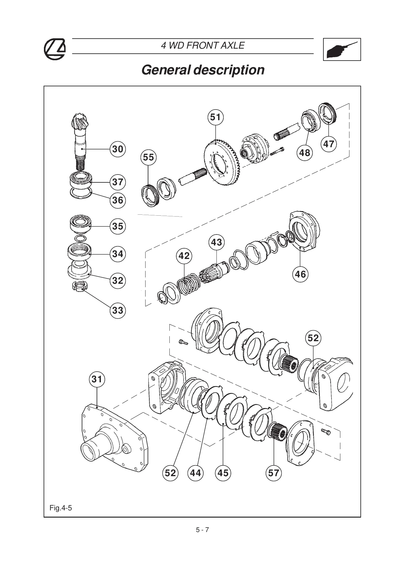
    1-1 Drawing of final drive assembly and main partsp. 175
    1-2 4WD clutch : Spring-onp. 179
    Sect.2 Technical specificationsp. 182
    2-1 Main technical specificationsp. 183
    2-2 Driving torques and sealantsp. 184
    Sect.3 Inspection and adjustmentsp. 186
    3-1 Inspectionp. 187
    3-2 Adjustments for the pinion-crown wheel assemblyp. 188
    3-3 Adjustments for the fork taper bearingsp. 192
    Sect.4 Special toolsp. 194
    Sect.4 Special toolsp. 195
    Chap.6 POWER TAKE-OFFp. 197
    Precautions and safety warningsp. 198
    Sect.1 General descriptionp. 199
    1-1 Drawing of assembly and main components (Rex 60-65-70-75-80)p. 200
    1-2 Drawing of assembly and main components (Rex 90-100)p. 202
    1-3 Description of operationp. 203
    1-4 Types of controlp. 204
    1-5 Sensor adjustmentp. 205
    Sect.2 Technical specificationsp. 207
    2-1 Main technical specificationsp. 208
    Chap.7 LOW PRESSURE HYDRAULIC CIRCUITp. 209
    Precautions and safety warnings.p. 210
    Sect.1 General descriptionp. 211
    1-1 Low pressure hydraulic circuitp. 212
    1-2 Description of the low pressure circuitp. 213
    Sect.2 Technical specifications.p. 215
    2-1 Main technical specificationsp. 216
    Sect.3 Main componentsp. 217
    A) Hydraulic pumpp. 218
    A1 – Description of operationp. 219
    B) Power steering systemp. 221
    B1 – Low pressure hydraulic circuitp. 222
    B2 – Power steering circuitp. 223
    B3 – Drawing of assembly and componentsp. 224
    B4 – Description of operationp. 226
    B5 – Dismantlingp. 230
    B6 – Inspectionp. 230
    B7 – Remounting and adjustmentp. 232
    C) Power clutch timing systemp. 235
    C1 – Main components and ductsp. 236
    C2 – Operation phases of the power clutch control valvep. 238
    C2.1 Phase with engaged PTO clutch, not engaged diff lock and engaged 4WDp. 239
    C2.2 Phase with engaged PTO clutch, engaged diff lock and engaged 4WDp. 240
    C2.3 Phase with engaged PTO clutch, engaged diff lock and not engaged 4WDp. 242
    C2.4 Phase with not engaged PTO clutch, not engaged diff lock and not engaged 4WDp. 244
    C2.5 Phase with not engaged PTO clutch, engaged diff lock and not engaged 4WDp. 246
    C2.6 Phase with Q link in progressive engagement of PTO clutch, not engaged diff lock and not engaged 4WDp. 248
    C2.7 Phase with engine off and PTO clutch control lever in engaged positionp. 250
    C3 – Solenoid valvesp. 252
    C4 – Adjustments and inspectionsp. 254
    C4.1 Calibration of 30 bar control valve springp. 255
    C4.2 Control and adjustment of PTO progressive engagement.p. 255
    C4.3 Calibration of 16 bar control valvep. 256
    C4.4 Control of 4WD engagement pressurep. 257
    D) Differential lock oil supplyp. 259
    D1 – Low pressure circuitp. 260
    D2 – Description of operationp. 261
    E) PTO power clutch cylinder oil supplyp. 263
    E1 – Low pressure hydraulic circuitp. 264
    E2 – Description of operationp. 265
    E3 – Adjustmentp. 266
    F) 4WD clutch oil supply (Spring-on)p. 267
    F1 – Low pressure circuitp. 268
    F2 – Description of operationp. 269
    Sect.4 Checking the operating pressure valuesp. 271
    4-1 Low pressure hydraulic circuitp. 272
    4-2 Low pressure circuit pressure checksp. 273
    Sect.5 Special toolsp. 275
    Sect.5 Special toolsp. 276
    Chap.8 HIGH PRESSURE STANDARD HYDRAULIC CIRCUITp. 277
    Precautions and Safety Recommendationsp. 278
    Sect.1 General descriptionp. 279
    1-1 High pressure hydraulic circuitp. 280
    1-2 Description of the circuitp. 281
    Sect.2 Technical specificationsp. 283
    2-1 Main technical specificationsp. 284
    Sect.3 Main componentsp. 285
    A – Pumpp. 287
    A1 – Main componentsp. 288
    A2 – Description of operationp. 289
    B – Trailer brake valvep. 291
    B1 – General descriptionp. 292
    B2 – Trailer brake valve – type for Italyp. 295
    B2-1 Phase with trailer coupled and pedal brakes not usedp. 295
    B2-2 Phase with trailer coupled and pedal brakes activatedp. 296
    B2-3 Phase with parking brake engaged and pedal brakes not usedp. 297
    B3 – Trailer brake valve – Export typep. 298
    B3-1 Phase with trailer coupled and pedal brakes not usedp. 299
    B3-2 Phase with trailer coupled and pedal brakes activatedp. 300
    C – Auxiliary control valvesp. 301
    C1 – General descriptionp. 302
    C2 – Control valves for Rex Vineyard tractorsp. 303
    C2-1 Flow dividerp. 305
    C2-2 Standard single and double-acting control valvep. 306
    C2-3 Single and double-acting control valve with floating positionp. 307
    C2-4 Single and double-acting control valve with automatic releasep. 308
    C2-5 Control valve for hydraulic enginesp. 309
    C3 -Control valves for Rex Orchard tractorsp. 310
    C3-1 Flow dividerp. 311
    C3-2 Standard control valvep. 312
    C4 – Electro-hydraulic flow selectorp. 314
    C4-1 General descriptionp. 315
    C4-2 Operation phasesp. 316
    D – Mechanical power lift oil supplyp. 321
    D – Mechanical power lift oil supplyp. 322
    E – Electronic power lift oil supplyp. 323
    E – Electronic power lift oil supplyp. 324
    F – Lubrication circuitp. 325
    F1 – General descriptionp. 326
    F2 – 1.5 bar governor valvep. 327
    Sect.4 Checking the operating pressure valuesp. 329
    4-1 Introductionp. 330
    4-2 Circuit pressure checksp. 330
    Sect.5 Special toolsp. 333
    Sect.5 Special toolsp. 334
    Chap.9 MECHANICAL POWER LIFTp. 335
    Precautions and Safety Recommendationsp. 335
    Sect. 1 General descriptionp. 337
    1-1 Drawing of assembly and main componentsp. 338
    1-2 Power lift operating modesp. 340
    1-3 Main components of the valve systemp. 344
    1-4 Operating phases of the valve systemp. 335
    Sect. 2 Technical specificationsp. 353
    2-1 Main technical specificationsp. 354
    2-2 Driving torques and sealantsp. 355
    Sect. 3 Inspections, adjustments and troubleshootingp. 357
    3-1 Hydraulic tests for valve systemp. 358
    3-2 Power lift adjustmentsp. 362
    3-3 Operating pressure testsp. 369
    3-4 Troubleshootingp. 370
    Sect. 4 Special toolsp. 371
    Sect. 4 Special toolsp. 372
    Chap.10 ELECTRONIC POWER LIFTp. 373
    Precautions and Safety Recommendationsp. 374
    Sect.1 General descriptionp. 375
    1-1 Main componentsp. 376
    1-2 Description of operationp. 377
    Sect.2 Technical specificationsp. 379
    2-1 Main technical specificationsp. 380
    Sect.3 Hydraulic circuitp. 381
    3-1 Description of general hydraulic circuit and main componentsp. 382
    3-2 Description of operationp. 383
    3-3 Control valve systemp. 384
    Sect.4 Electrical systemp. 389
    4-1 Introductionp. 390
    4-2 Electrical wiring diagramp. 391
    4-3 Wiring and types of connectorp. 392
    4-4 Connector locationsp. 394
    4-5 Main electrical/electronic componentsp. 395
    A – Control consolep. 396
    B – Electronic plantp. 399
    C – External buttonp. 400
    D – Sensorsp. 400
    4-6 Shock absorber functionp. 403
    Sect.5 Functionality testsp. 405
    5-1 Introductionp. 406
    5-2 Quick function testp. 406
    Sect.6 Check-control and troubleshootingp. 415
    6-1 How to identify a faultp. 416
    6-2 Monitoring instrumentsp. 417
    6-3 Fault code tablep. 418
    6-4 Wiring diagramp. 422
    6-5 Connector terminal matchesp. 423
    Sect.7 Hydraulic testsp. 425
    7-1 Operating pressure testsp. 426
    Sect.8 Special toolsp. 427
    Sect.8 Special toolsp. 428
    Chap.11 ELECTRICAL SYSTEMp. 429
    Precautions and Safety recommendationsp. 430
    Sect.1 General descriptionp. 431
    1-1 Basic conceptsp. 432
    1-2 Electricity symbolsp. 441
    Sect.1 Wiringp. 447
    2-1 Introductionp. 448
    2-2 Cable colour chartp. 449
    2-3 General location of the wiringp. 450
    2-4 Battery-starter motor linep. 455
    2-4.1 General descriptionp. 456
    2-4.2 Wiring diagramp. 457
    Sect.3 Technical specifications and diagramsp. 429
    A____Rex Orchard footstep tractorsp. 429
    3A.1 Version for EUROPEp. 459
    A1.1 Technical specificationsp. 461
    A1.1-1 Main technical specificationsp. 462
    A1.1-2 Relays and fuse holdersp. 463
    A1.1-3 Main wiring diagramp. 468
    A1.2 Wiringp. 473
    A1.2-1 Wiring diagram of front engine linep. 474
    A1.2-2 Multiple-wiring diagram of front engine linep. 475
    A1.2-3 Wiring diagram of dashboard linep. 476
    A1.2-4 Multiple-wiring diagram of dashboard linep. 477
    A1.2-5 Wiring diagram of rear linep. 478
    A1.2-6 Multiple-wiring diagram of rear linep. 479
    3A.2 NAO versionp. 481
    A2.1 Technical specificationsp. 483
    A2.1-1 Main technical specificationsp. 484
    A2.1-2 Relays and fuse holdersp. 485
    A2.1-3 Main wiring diagramp. 490
    A2.2 Wiringp. 495
    A2.2-1 Wiring diagram of front engine linep. 496
    A2.2-2 Multiple-wiring diagram of front engine linep. 497
    A2.2-3 Wiring diagram of dashboard linep. 498
    A2.2-4 Multiple-wiring diagram of dashboard linep. 499
    A2.2-5 Wiring diagram of rear linep. 500
    A2.2-6 Multiple-wiring diagram of rear linep. 501
    B____Rex Orchard cab tractorsp. 429
    3B.1 Version for EUROPEp. 503
    B1.1 Technical specificationsp. 505
    B1.1-1 Main technical specificationsp. 506
    B1.1-2 Relays and fuse holdersp. 507
    B1.1-3 Main wiring diagramp. 512
    B1.2 Wiringp. 517
    B1.2-1 Wiring diagram of front engine linep. 518
    B1.2-2 Multiple-wiring diagram of front engine linep. 519
    B1.2-3 Wiring diagram of dashboard linep. 520
    B1.2-4 Multiple-wiring diagram of dashboard linep. 521
    B1.2-5 Wiring diagram of platform linep. 522
    B1.2-6 Multiple-wiring diagram of platform linep. 523
    B1.2-7 Wiring diagram of rear linep. 524
    B1.2-8 Multiple-wiring diagram of rear linep. 525
    3B.2 NAO versionp. 527
    B2.1 Technical specificationsp. 529
    B2.1-1 Main technical specificationsp. 530
    B2.1-2 Relays and fuse holdersp. 531
    B2.1-3 Main wiring diagramp. 536
    B2.2 Wiringp. 541
    B2.2-1 Wiring diagram of front engine linep. 542
    B2.2-2 Multiple-wiring diagram of front engine linep. 543
    B2.2-3 Wiring diagram of dashboard linep. 544
    B2.2-4 Multiple-wiring diagram of dashboard linep. 545
    B2.2-5 Wiring diagram of platform linep. 546
    B2.2-6 Multiple-wiring diagram of platform linep. 547
    B2.2-7 Wiring diagram of rear linep. 548
    B2.2-8 Multiple-wiring diagram of rear linep. 549
    C____Rex Vineyard footstepp. 429
    3C.1 Version for Europep. 551
    C1.2 Technical specificationsp. 553
    C1.1-1 Main technical specificationsp. 554
    C1.1-2 Relays and fuse holdersp. 555
    C1.1-3 Main wiring diagramp. 560
    C1.2 Wiringp. 553
    C1.2-1 Wiring diagram of front engine linep. 566
    C1.2-2 Multiple-wiring diagram of front engine linep. 567
    C1.2-3 Wiring diagram of dashboard linep. 568
    C1.2-4 Multiple-wiring diagram of dashboard linep. 569
    C1.2-5 Wiring diagram of rear linep. 570
    C1.2-6 Multiple-wiring diagram of rear linep. 571
    3C.2 NAO versionp. 573
    C2.1 Technical specificationsp. 575
    C2.1-1 Main technical specificationsp. 576
    C2.1-2 Relays and fuse holdersp. 577
    C2.1-3 Main wiring diagramp. 582
    C2.2 Wiringp. 587
    C2.2-1 Wiring diagram of front engine linep. 588
    C2.2-2 Multiple-wiring diagram of front engine linep. 589
    C2.2-3 Wiring diagram of dashboard linep. 590
    C2.2-4 Multiple-wiring diagram of dashboard linep. 591
    C2.2-5 Wiring diagram of rear linep. 592
    C2.2-6 Multiple-wiring diagram of rear linep. 593
    D____Rex Vineyard cab tractorsp. 429
    3D.1 Version for Europep. 595
    D1.1 Technical specificationsp. 597
    D1.1-1 Main technical specificationsp. 598
    D1.1-2 Relays and fuse holdersp. 599
    D1.1-3 Main wiring diagramp. 604
    D1.2 Wiringp. 609
    D1.2-1 Wiring diagram of front engine linep. 610
    D1.2-2 Multiple-wiring diagram of front engine linep. 611
    D1.2-3 Wiring diagram of dashboard linep. 612
    D1.2-4 Multiple-wiring diagram of dashboard linep. 613
    D1.2-5 Wiring diagram of platform linep. 614
    D1.2-6 Multiple-wiring diagram of platform linep. 615
    D1.2-7 Wiring diagram of dashboard line (GE version)p. 616
    D1.2-8 Multiple wiring diagram of dashboard line (GE version)p. 617
    D1.2-9 Wiring diagram of platform line (GE version)p. 618
    D1.2-10 Multiple wiring diagram of platform line (GE version)p. 619
    D2.2-11 Wiring diagram of rear linep. 620
    D2.2-12 Multiple-wiring diagram of rear linep. 621
    3D.2 NAO versionp. 623
    D2.1 Technical specificationsp. 625
    D2.1-1 Main technical specificationsp. 626
    D2.1-2 Relays and fuse holdersp. 627
    D2.1-3 Main wiring diagramp. 632
    D2.2 Wiringp. 637
    D2.2-1 Wiring diagram of front engine linep. 638
    D2.2-2 Multiple-wiring diagram of front engine linep. 639
    D2.2-3 Wiring diagram of dashboard linep. 640
    D2.2-4 Multiple-wiring diagram of dashboard linep. 641
    D2.2-5 Wiring diagram of platform linep. 642
    D2.2-6 Multiple-wiring diagram of platform linep. 643
    D2.2-7 Wiring diagram of rear linep. 644
    D2.2-8 Multiple-wiring diagram of rear linep. 645
    Chap.12 AIR CONDITIONING SYSTEMp. 647
    Sect.1 General descriptionp. 649
    1-1 Basic principlesp. 650
    1-2 Operating principle of a chilling cyclep. 660
    1-3 Main components of an air conditioning systemp. 665
    Sect.2 Technical specificationsp. 669
    2-1 Main technical specificationsp. 670
    Sect.3 Air-conditioning system (AC)p. 671
    3-1 Main componentsp. 672
    3-2 How to use the air-conditioning systemp. 673
    3-3 Wiring diagramp. 674
    Sect.4 Emptying and charging the systemp. 677
    4-1 Safety notesp. 678
    4-2 Maintenance instructionsp. 679
    4-3 Recharging procedurep. 680
    Sect.5 Functionality testsp. 685
    5-1 Equipment requiredp. 686
    5-2 Checking the efficiency of the system (AC)p. 687
    5-3 Check-control tablesp. 688
    Chap.13 SPECIAL TOOLSp. 690
    Sect.1 Drawingsp. 690
    01 FRI REXp. 692
    01 CMB REXp. 693
    01 DIF MYTp. 694
    01 DT REXp. 695
    02 DT REXp. 697
    03 DT REXp. 698
    04 DT REXp. 699
    01 IDR REXp. 700
    02 IDR REXp. 701
    03 IDR REXp. 702
    02 IDR MYTp. 703
    03 IDR MYTp. 704
    122 IDR GL122 IDR GL122 IDR GLp. 705
    CR 342p. 706
    R 504p. 708

  • Chapter 12 – Air-conditioning system
    • Basic principles of pressure, heat, temperature and physical state changes
    • Operating principle of the cooling cycle
    • Main components – coolant, evaporator, compressor, condenser, expansion valve and dehydrator filter
    • Technical specifications
    • Air-conditioning system layout, controls and wiring
    • Emptying and charging the system, safety notes and recharging procedure
    • Functionality tests and check-control tables
  • Chapter 13 – Special tools
    • Drawings and dimensions of the full Landini special tool range referenced throughout the manual

What This Manual Gives a Technician

The Rex 60-100 V GE F L GT training manual is built around the procedures that separate a correct repair from an expensive repeat job. Engine timing on both the 903.27 and the 1004.40 / 1004.42 / 1004.40T families is covered step by step, including how to find compression TDC on cylinder number 1, how to verify camshaft timing against the pulley mark, and how to use the Perkins timing plug and locking angle tooling on the injection pump. The transmission and rear axle chapters give the shim calculations for pinion position, taper bearing preload and crown wheel backlash, with worked examples so the numbers can be followed directly on the bench. The hydraulic chapters describe every operating phase of the power clutch control valve and the trailer brake valve, so a pressure fault can be traced to a specific plunger, spring or calibration shim rather than guessed at. The electrical chapter goes further than most: separate wiring diagrams and fuse tables are provided for Orchard and Vineyard tractors in both footstep and cab versions, and for both Europe and NAO markets, with connector terminal correspondence tables that make tracing a circuit practical.

Coverage Notes

This is a training manual rather than a single-model workshop manual, so it deliberately spans the whole Rex Orchard and Rex Vineyard range. Where a specification, torque value or dimension differs between the 60, 65, 70, 80, 90 and 100, or between the V, GE, F, L and GT versions, the tables present the values side by side. Reading the correct column for your tractor is part of using the document properly. Some assemblies are described at a level aimed at the chief foreman, focusing on the operations that need specific expertise, tooling or recommendations rather than every routine demounting step. Three-cylinder tractors use the Perkins 903.27 or 903.27T engine, while the 70, 80, 90 and 100 use the four-cylinder 1004.40, 1004.42 or 1004.40T depending on the version, and the manual treats each engine family in its own timing section.

What You Can Do With This Landini Rex Training Manual

With this manual open on the bench you can set and verify engine timing on the Perkins 903.27 and 1004 series engines, calculate and fit the correct shims for the rear bevel gear pair and differential, preload the taper bearings to the specified moment of rotation, adjust the 4WD front axle pinion and fork bearings, rebuild the twin-plate clutch and set lever coplanarity, service the independent PTO and its speed sensor, and diagnose the low pressure and high pressure hydraulic circuits using the documented operating phases and pressure check values. On the electrical side you can trace faults through the Orchard and Vineyard wiring diagrams, identify the correct fuse and relay for a circuit, and check connector terminals against the correspondence tables. The electronic power lift chapter adds fault code interpretation and a rapid function test procedure, and the air conditioning chapter covers recovery, evacuation, charging and efficiency checking with pressure and temperature reference tables.

Correct procedures and correct specifications are what protect the machine. A pinion shim calculated from the stamped housing dimension and the marking on the pinion end is a different job from one estimated by feel, and the torque tables in this manual remove that guesswork. The pressure values for the power clutch control valve, the differential lock and the Spring-on 4WD clutch are all given with adjustment shim sensitivities, so a valve that is slightly out of calibration can be brought back rather than replaced.

IMAGES PREVIEW

Landini Rex 60-100 V GE F L GT Tractor Training Manual 3659961M2 - PDF Download β€” PDF page 1 preview
Landini Rex 60-100 V GE F L GT Tractor Training Manual 3659961M2 - PDF Download β€” PDF page 126 preview
Landini Rex 60-100 V GE F L GT Tractor Training Manual 3659961M2 - PDF Download β€” PDF page 178 preview

Instant PDF Delivery

The manual is supplied as a PDF and is available immediately after payment. There is no shipping and nothing to wait for in the post. The file opens on any device – desktop, laptop, tablet or phone – and every page can be printed if you prefer a paper copy in the workshop. Keep it on the service laptop, print the timing and torque pages for the job in hand, or store it alongside your other Landini Rex documentation. Either way, the complete 3659961M2 training manual is in your hands the moment you check out.
Reviews

There are no reviews yet.

Be the first to review “Landini Rex 60-100 V GE F L GT Tractor Training Manual 3659961M2 – PDF Download”

What Our Customers Say

β˜…β˜…β˜…β˜…β˜… Live reviews from customers
Loading customer reviews...
0
    0
    Your Cart
    Your cart is emptyReturn to Shop
    πŸ›’
    Recently Purchased
    πŸ•’ verified order