
Massey Ferguson 6400 Series Tractor Electronics Section Workshop Manual – PDF
Original price was: $39.95.$23.95Current price is: $23.95.
Complete electronics workshop manual for Massey Ferguson 6400 series tractors covering Perkins and SisuDiesel electronic injection, DCC2 panels, Autotronic 3 and 5 transmission controllers, EHRC linkage, Datatronic systems, SMS joystick controls, and suspended front axle electronics with diagnostics, error codes, calibration procedures, and wiring diagrams.
Description
Massey Ferguson 6400 Series Tractor Electronics Section Workshop Manual
This workshop manual covers the complete electronics section for Massey Ferguson 6400 series tractors and related 5400, 7400, and 8400 models. It is the definitive technical reference for the electronic injection systems, transmission controllers, linkage management, instrument panels, and diagnostic procedures used across this tractor range. The content spans from the Perkins EEM electronic engine management on early models through to the SisuDiesel EEM2 system and the full suite of DCC2 and Autotronic controllers.
File Details
- Manual type: Workshop Manual – Electronics Section
- Brand: Massey Ferguson
- Model series: 6400, 7400, 8400, 5400 series tractors
- Language: English
- Page count: 1200
- File format: PDF
Chapters Covered
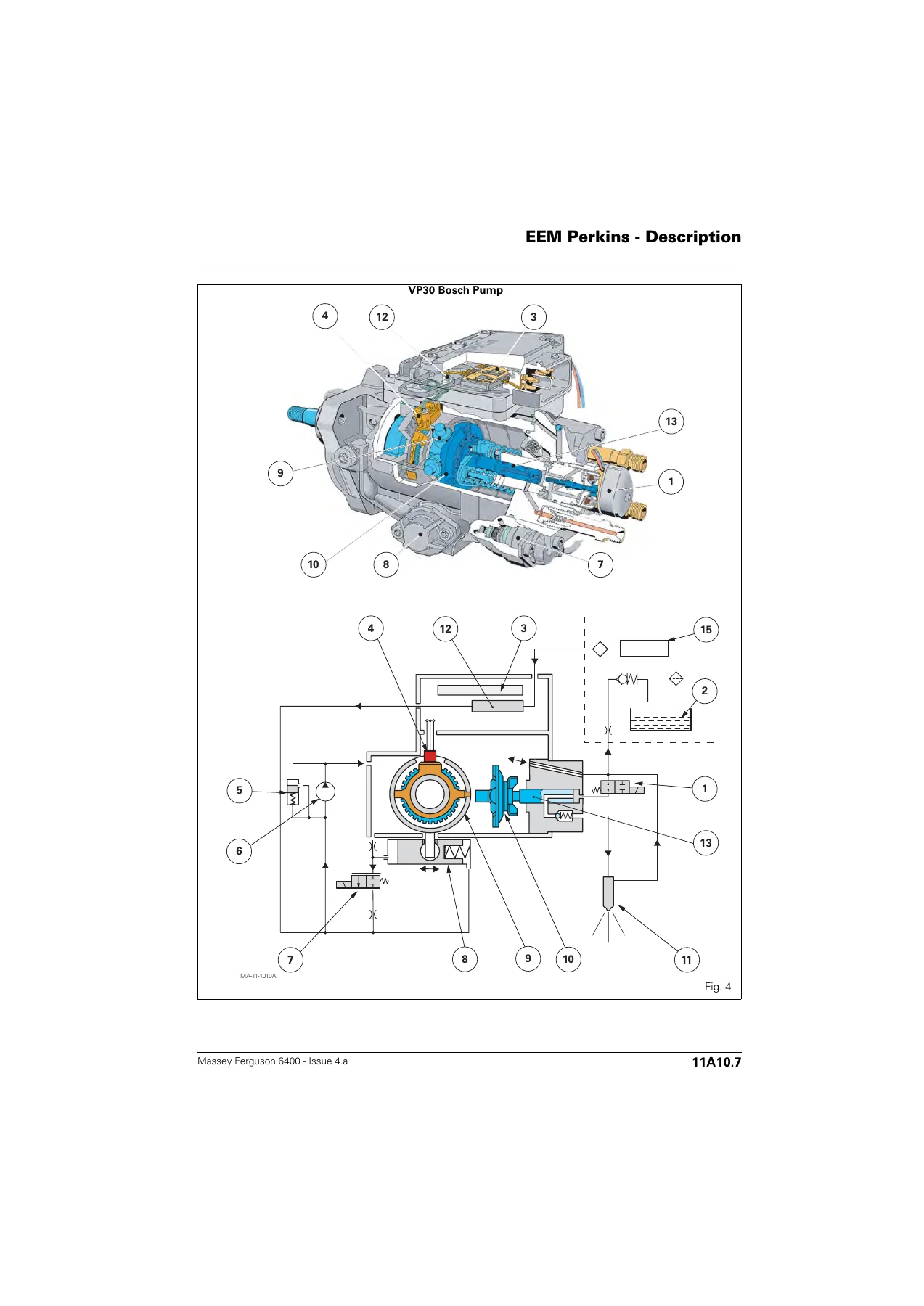
- Electronic Injection – Perkins EEM: Description, Components, Communication, Cab Controls, Programming, Tests and Diagnostics, Error Codes, Electrical Diagrams
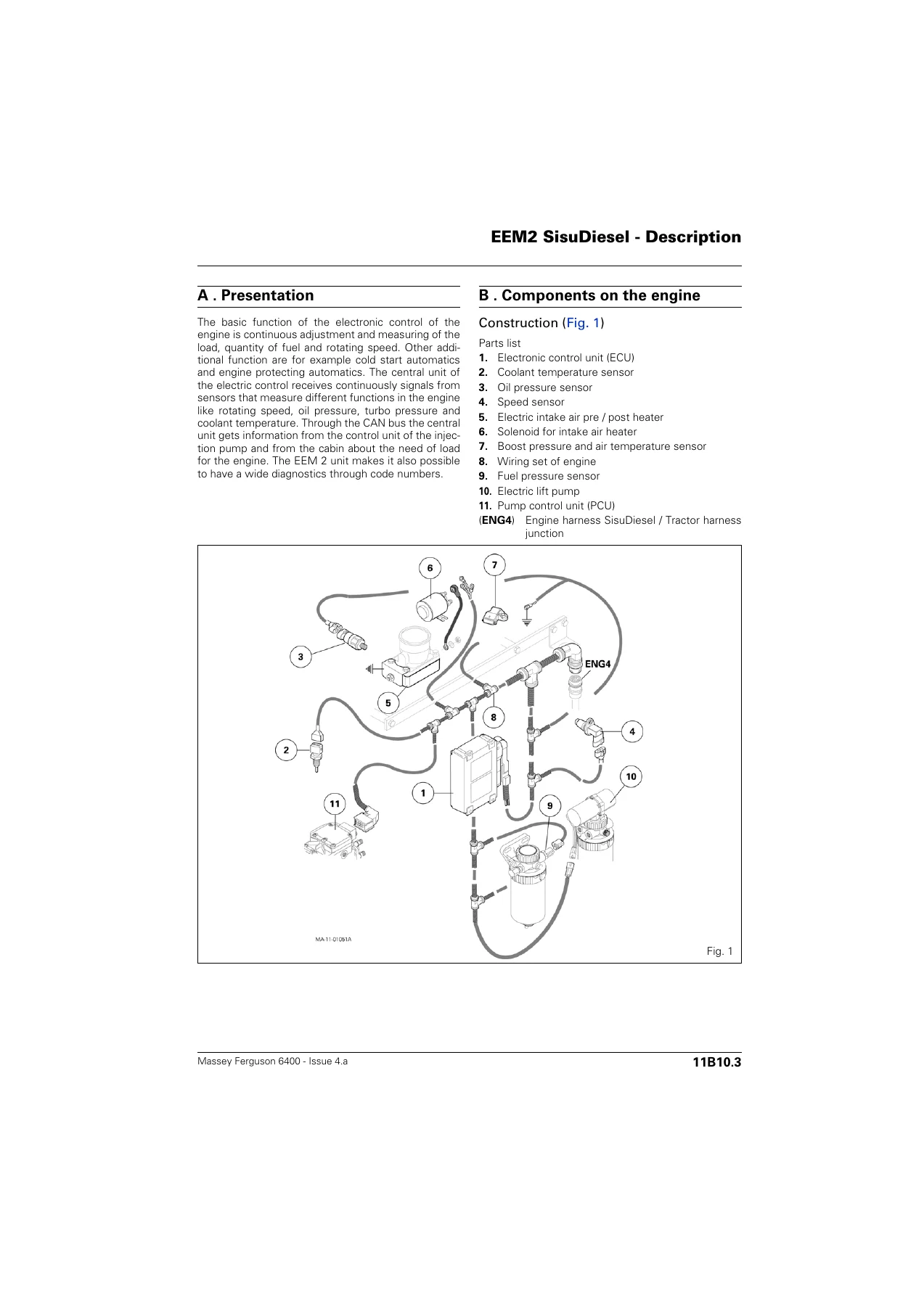
- Electronic Injection – SisuDiesel EEM2: Description, Components, Programming with WinEEM3, Tests and Diagnostics, Error Codes, Electrical Diagrams
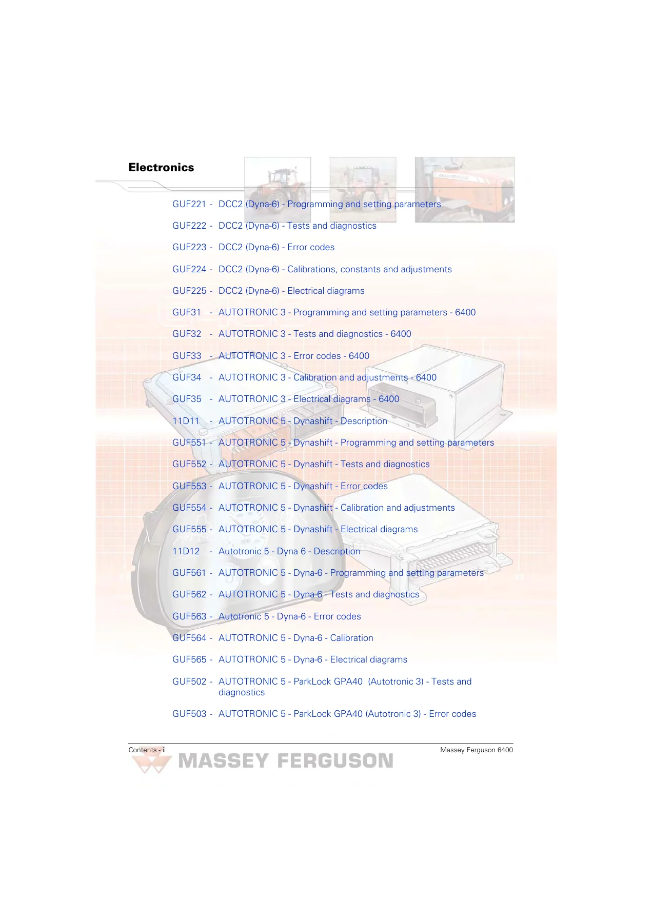
- DCC2 – Dynashift: Description, Programming and Setting Parameters, Error Codes, Calibrations and Constants, Tests and Diagnostics
- DCC2 – Dynashift with Autotronic 5: Programming and Setting Parameters, Tests and Diagnostics, Error Codes, Calibrations Constants and Adjustments, Electrical Diagrams
- DCC2 – Dyna-6: Description, Programming and Setting Parameters, Tests and Diagnostics, Error Codes, Calibrations Constants and Adjustments, Electrical Diagrams
- Autotronic 3: Programming and Setting Parameters, Tests and Diagnostics, Error Codes, Calibration and Adjustments, Electrical Diagrams
- Autotronic 5 – Dynashift: Description, Programming and Setting Parameters, Tests and Diagnostics, Error Codes, Calibration and Adjustments, Electrical Diagrams
- Autotronic 5 – Dyna-6: Description, Programming and Setting Parameters, Tests and Diagnostics, Error Codes, Calibration, Electrical Diagrams
- Autotronic 5 – ParkLock GPA40: Tests and Diagnostics, Error Codes, Electrical Diagrams
- Autotronic 5 – Linkage (EHRC): Description, Programming and Setting Parameters, Tests and Diagnostics, Error Codes, Calibration and Adjustments, Electrical Diagrams
- EHRC – Linkage: Description, Setting Parameters, Tests and Diagnostics, Error Codes, Adjustments, Electrical Diagrams
- Datatronic 2: Programming and Setting Parameters, Tests and Diagnostics, Error Codes
- Datatronic 3: Programming, Calibration and Adjustments, Electrical Diagrams
- SMS – Joystick / FingerTIP: Description, Programming and Setting Parameters, Tests and Diagnostics, Error Codes, Settings, Electrical Diagrams for EHRC and Auto 5 linkage
- Autotronic 5 – Suspended Front Axle (DANA): Description, Programming and Setting Parameters, Tests and Diagnostics, Error Codes, Calibration and Adjustments, Electrical Diagrams
- Autotronic 5 – Suspended Front Axle (CARRARO): Programming, Tests and Diagnostics, Error Codes, Calibration and Adjustments, Electrical Diagrams
This manual gives technicians and owners the complete electronic diagnostic and repair capability for the Massey Ferguson 6400 series. It covers the transition from Perkins mechanical and electronic injection systems through to the SisuDiesel EEM2 platform, including the DCC2 instrument panel used across Dynashift and Dyna-6 transmissions. The Autotronic 3 and Autotronic 5 transmission controllers are documented with full programming parameters, error code tables, diagnostic screens, and calibration routines. The EHRC linkage system is covered in depth, from console controls and draft sensors through to position sensor adjustment and Dual Control calibration. The SMS joystick and FingerTIP spool valve management system is explained with parameter setting procedures and error code interpretation. Suspended front axle electronics are documented for both DANA and CARRARO axles, including sensor adjustment and calibration. Throughout the manual, error codes are listed with their component, reaction of the system, and troubleshooting steps, making this a practical fault-finding resource as well as a reference for programming and parameter setting via Wintest and EST software.
Programming and Diagnostic Software Coverage
The manual details the use of AGCO diagnostic tools including Wintest, EST, WinEEM3, and WinFlash for programming and parameter setting. It explains how to match injection pump serial numbers to the ECU, how to download new software to the ECM, how to set tractor label codes, and how to navigate the diagnostic screens. For each electronic controller, the manual describes the parameter codes, the available software versions, and the procedures for saving and restoring controller data. The error code sections provide the DCC2 display format, the flash code sequences on indicator lights, and the corresponding fault descriptions with recommended actions. This level of detail allows the technician to diagnose faults accurately and carry out repairs or component replacements with the correct software configuration.
Electrical Diagrams and Wiring
Electrical diagrams are included for the Perkins engine harness, the SisuDiesel engine harness, and the tractor-level wiring for both DCC2 and non-DCC2 configurations. The diagrams show connector pin allocations, wire colours, splices, and harness junctions. CAN network diagrams are provided for all options with Autotronic 3, Autotronic 4, and Autotronic 5 transmission controllers, as well as for linkage, ParkLock, and suspended front axle systems. These diagrams are essential for tracing faults, verifying continuity, and understanding the communication architecture between the various electronic controllers on the tractor.
Who This Manual Is For
This electronics section is intended for professional tractor technicians, fleet maintenance engineers, agricultural mechanics, and knowledgeable owners who need to diagnose and repair the electronic systems on Massey Ferguson 6400 series tractors. It assumes familiarity with tractor mechanics and electrical principles but provides the specific procedures, parameter values, and diagnostic steps required for these machines. The manual is particularly valuable for anyone who needs to program a replacement controller, calibrate a sensor, interpret an error code, or trace a wiring fault on these tractors.
Get Instant Access to the Complete Electronics Manual
IMAGES PREVIEW
With this Massey Ferguson 6400 Series Tractor Electronics Section Workshop Manual, you can perform advanced diagnostics, program controllers, calibrate transmission and linkage systems, and resolve electronic faults with confidence. The manual provides the correct procedures and specifications so you avoid guesswork and prevent damage to sensitive electronic components. Delivered as an instant PDF download, there is no shipping and no waiting. You can view the manual on any device, print the pages you need for the workshop, and keep it as a permanent reference for the tractors you maintain. Whether you are diagnosing a DCC2 error code, programming a new Autotronic 5 controller, or calibrating a suspended front axle, this manual gives you the technical information required to complete the job correctly.
Reviews
There are no reviews yet.