
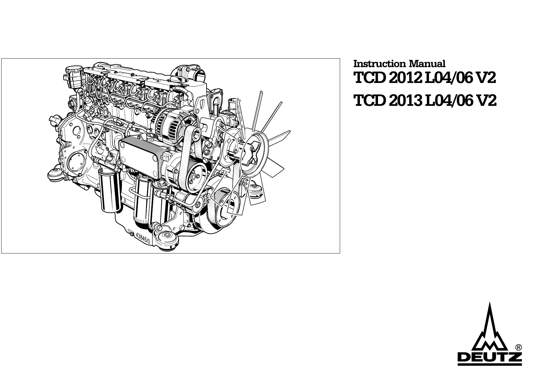
Deutz TCD 2012 L04/L06 V2 & TCD 2013 L04/L06 V2 Instruction Manual – Operator’s PDF 312 1890
Original price was: $44.95.$29.95Current price is: $29.95.
Complete DEUTZ instruction manual (doc. 312 1890 en) for the TCD 2012 L04/L06 2V and TCD 2013 L04/L06 2V liquid-cooled diesel engines. 101 pages of commissioning, operation, maintenance schedules, valve and control piston setting, EMR3 blink-code diagnostics, torque values and DEUTZ original-parts guidance – instant PDF download.
Description
File Details
- Manual type: Instruction / operator’s manual
- Manufacturer: DEUTZ AG
- Engines covered: TCD 2012 L04 2V, TCD 2012 L06 2V, TCD 2013 L04 2V, TCD 2013 L06 2V
- Document number: 312 1890 en
- Language: English
- File format: PDF
- Page count: 101 pages
Deutz TCD 2012 L04/L06 V2 and TCD 2013 L04/L06 V2 Instruction Manual – What This Document Is
This is the full DEUTZ instruction manual covering the liquid-cooled TCD 2012 L04/06 V2 and TCD 2013 L04/06 V2 diesel engines. It is the document that ships with the engine, written for the operator and the workshop that has to keep the unit running: initial commissioning, daily operation, the complete maintenance schedule, setting work on valves and the EGR control piston, and the fault-finding routines for the EMR3 electronic engine control. It does not assume you already know the engine – it walks through the fill points, the oil and coolant specifications, the belt drive, the fuel and lube oil circuits and the safety rules that govern working on a common rail fuel system.
Because the TCD 2012 and TCD 2013 families share one manual, the document separates the differences where they matter: the 2013 series uses Deutz Common Rail (DCR) with a high-pressure pump and rail feeding the injectors, while the pump-line-nozzle (PLD) arrangement is described alongside it. The engine diagrams are printed for the four-cylinder and six-cylinder variants on both the operation side and the starter side, so you can identify a component on the machine in front of you rather than guessing from a generic drawing.
Chapters Covered
- 1. General
- 2. Engine description
- 3. Operation
- 4. Operating substances
- 5. Maintenance
- 6. Care and maintenance work
- 7. Faults, causes and remedies
- 8. Engine corrosion protection
- 9. Technical data
- 10. Service
General
The opening chapter sets out what DEUTZ expects from the person operating and maintaining the engine: use for the intended purpose, the danger zones around a running engine (rotating and hot components, high electrical voltage on engines with extraneous ignition), and the rule that maintenance is only carried out on a stopped, cooled engine with the electrical system switched off. It also spells out the fuel-system safety position clearly – do not work on the fuel system while the engine is running, wait one minute after shutdown for the system pressure to release, and stand clear of the danger area during the first trial run because of the risk from high-pressure leaks.
Engine Description and Identification
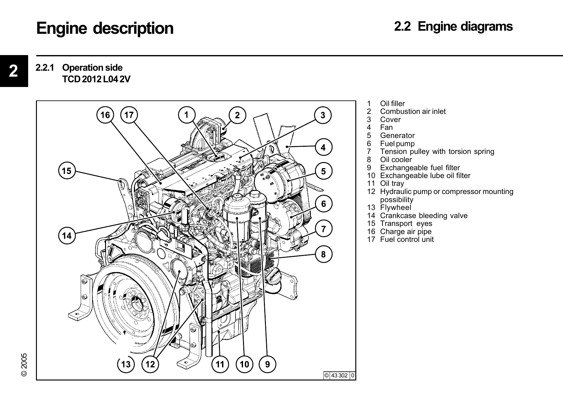
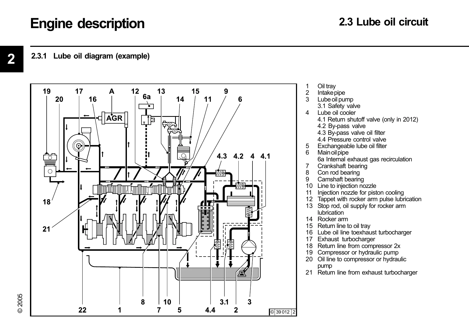
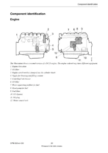
This is where you learn to read your own engine. It covers the company plate, its location, the engine number stamped on the crankcase, and the cylinder numbering convention (counted consecutively starting from the flywheel). Full engine diagrams follow for the TCD 2012 L04 2V, L06 2V and the TCD 2013 L04 2V and L06 2V, each shown from the operation side and the starter side, with numbered callouts for the oil filler, combustion air inlet, fan, generator, fuel pump, tension pulley with torsion spring, oil cooler, exchangeable fuel and lube oil filters, oil tray, flywheel, crankcase bleeding valve, transport eyes, charge air pipe, fuel control unit, exhaust manifold, turbocharger, coolant pump and inlet/outlet, rail, injectors and SAE housing. Schematic circuits for the lube oil, fuel and coolant systems and the electrical monitoring connections complete the chapter.
Operation
Initial commissioning is covered step by step: filling engine oil through the oil filler on the cylinder head cover (with the alternative fill points noted), filling fuel, and filling and bleeding the cooling system – connect the coolant outlet and inlet, connect the compensation tank lead line, fill through the compensation tank, run the engine warm until the thermostat opens and check the level again. Starting is described for the electrical system with the key positions and the pre-heat sequence for the heating plug/heating flange, including the maximum uninterrupted cranking time and the pause between attempts. Operation monitoring explains the oil pressure light and gauge, the coolant temperature display bands, and the coolant level warning. Shutdown covers the key-off routine and the note that the control unit stays active for around 40 seconds to save system data, plus the instruction to idle for about a minute after load to protect the turbocharger. Winter operation, high ambient temperature and high altitude guidance round out the chapter.
Operating Substances
Lube oil, fuel and coolant specifications in one place. The oil chapter explains the DEUTZ Quality Class system (DQC I through DQC IV) with the equivalent ACEA and API classifications, a release list of approved products and SAE viscosity selection against ambient temperature. The fuel chapter gives the permitted diesel specifications (DIN EN 590, ASTM D 975 Grade 1-D and 2-D, JIS K 2204 Grade 1 and Grade 2) with the sulfur limit and the winter fuel and paraffin mixing diagram. The coolant chapter covers water analysis values (pH, chloride, sulfate, total hardness), conditioning with ethylene-glycol-based inhibitors, and the preservative-to-water mixing ratios that give protection down to -22 degrees C, -28 degrees C and -35 degrees C.
Maintenance
The standard maintenance schedule is laid out in job-time intervals from E 10 through E 70 (50 oh, 10 oh or daily, 500 oh, 1000 oh, 1500 oh, 3000 oh, 5000 oh, 6000 oh and 12000 oh), with each activity marked as check, set, clean or renew and with the execution level identified – user, authorised specialist or authorised service personnel. The self-adhesive maintenance diagram supplied with every engine is reproduced for both the TCD 2012 L04/06 2V and the TCD 2013 L04/06 2V, and a log table lets you record operating hours, date and signature as the work is carried out.
Care and Maintenance Work
This is the hands-on chapter and the reason most people keep this manual on the bench. Lubrication system: oil change intervals by DQC class, checking the oil level on the dipstick, draining and refilling, changing the spin-on lube oil filter cartridge and servicing the lube oil filter cup with its paper cartridge, sealing ring and guide. Fuel system: changing the fuel filter, the fuel pre-filter with water collecting vessel and drain cock, and the full bleeding procedure using the fuel hand pump bayonet plug and thermostat valve shutdown lever. Cooling system: cleaning with compressed air, cold cleaner, steam or hot water, emptying at the crankcase locking screw, and filling/bleeding. Combustion air filter: cleaning intervals, the cyclone pre-separator, the oil bath air filter and the dry air filter with dust discharge valve and safety cartridge. Belt drive: checking V-belt tension with the measuring device, changing the V-rib belt using the tension roller and locking pin, and checking the wear limit at the tensioner housing. Setting work: valve clearance and EGR control piston clearance using the rotation angle disc, with the setting diagram for both the four-cylinder (1-3-4-2) and six-cylinder (1-5-3-6-2-4) firing orders and the rotation angle values for the 2012 and 2013 engines. Add-on parts: battery checks, acid level and density, the three-phase current generator notes, and the correct transportation suspension.
Faults, Causes and Remedies
A fault table for mechanical and operating problems, followed by the engine management chapter on the EMR3 electronic engine control. It explains the engine protection function, how the diagnostic lamp behaves (lamp test, steady light, fast flashing) and how to read the stored faults as blink codes using the diagnosis button – with the full blink-code table covering coolant temperature and oil pressure outputs, accelerator and multi-step switch inputs, rail pressure monitoring and limiting valve, camshaft/crankshaft signals, overspeed, charge air and fuel low-pressure sensors, water level in the fuel filter, coolant level, misfiring, sensor supply voltage, CAN-Bus timeout, cold start aid, start relay and terminal 15/50 monitoring, plus the note on what to check when a signal is faulty or implausible.
Engine Corrosion Protection
Procedures for shutting an engine down for up to about six months: the corrosion protection oil specifications, how to clean and warm the engine, drain the oil and coolant, fill the protection mixture, run the engine, seal the intake and exhaust openings and the coolant nozzles, remove and store the V-belt, and then how to remove the protection and return the engine to service.
Technical Data, Tightening Torques and Special Tools
Engine and setting data for the TCD 2012 and TCD 2013 four- and six-cylinder versions – cylinder arrangement, bore, stroke, total displacement, compression ratio, charge air cooler data, direction of rotation, injection system, approximate weight, nominal speed, valve clearance, ignition pressure, firing sequence and V-belt tension. Coolant quantity, permissible continuous coolant temperature, thermostat opening values, maximum oil temperature, minimum oil pressure in warm condition and initial oil filling quantities are tabulated alongside screw tightening torques for the cylinder head cover, valve lock nut, front face mounting foot and oil drain screw. The tools chapter lists the special equipment with order numbers: TORX set, V-belt tension measuring device, rotation angle disc for valve and control piston clearance, valve clearance and control piston wrench inserts, crow’s foot wrench and the turning gear.
Who This Deutz TCD 2012/2013 V2 Operator’s Manual Is For
Owners and operators of machinery running a TCD 2012 or TCD 2013 four- or six-cylinder engine, fleet maintenance planners building a service schedule around the E 10 to E 70 intervals, and independent workshops that need the correct setting values rather than a generic diesel engine guide. It is also the reference to hand to a new technician so the safety rules on the common rail system and the crankcase bleeding, filter and belt procedures are followed the same way every time. Because the manual documents both the 2012 and 2013 series, it stays useful across mixed equipment fleets.
Get the Torque, Clearance and Blink-Code Data Before the Next Job
This Deutz TCD 2012 L04/L06 V2 and TCD 2013 L04/L06 V2 instruction manual gives you the material to commission an engine correctly, run it within its limits, and carry out the maintenance that keeps the DEUTZ warranty and the engine’s service life intact – oil and filter changes, fuel pre-filter servicing and bleeding, cooling system cleaning and filling, air filter maintenance, V-rib belt replacement, valve clearance and EGR control piston setting with the rotation angle disc, and fault diagnosis through the EMR3 blink codes. It also carries the values that prevent expensive mistakes: oil pressure and temperature limits, coolant temperature bands, filling quantities, tightening torques and the documented special tools needed for the setting work.
IMAGES PREVIEW
Wrong clearances, an unbled fuel system or a misread blink code are exactly the situations that turn a routine service into a repair, so working from the printed DEUTZ procedure and the correct specification is the cheap option. The manual is delivered as an instant PDF download after checkout – no shipping, no waiting – and it opens on a laptop, tablet or phone in the workshop or in the field, with every page available to print for the bench or for the machine’s document folder.
Reviews
There are no reviews yet.