
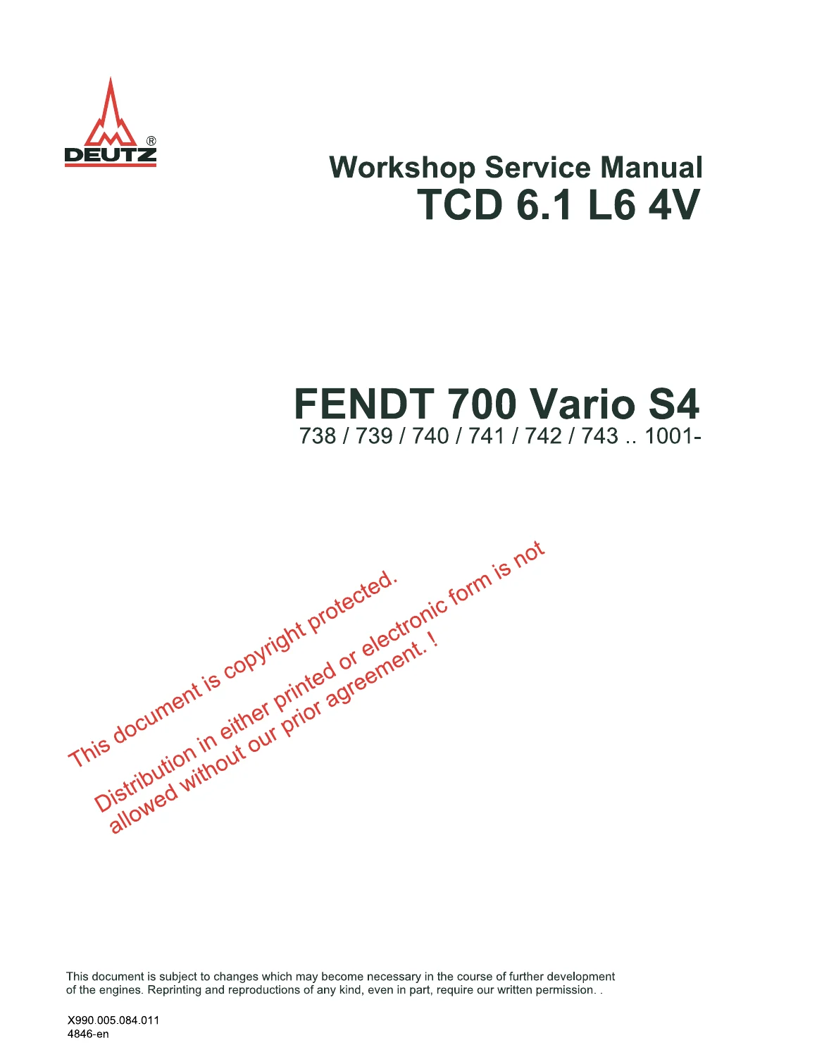
Deutz TCD 6.1 L6 4V Fendt 700 Vario S4 Workshop Service Manual PDF
Original price was: $49.95.$29.95Current price is: $29.95.
Workshop service manual for the DEUTZ TCD 6.1 L6 4V engine as used in the FENDT 700 Vario S4 application. This 577-page PDF contains illustrated job cards for engine disassembly, inspection, measurement, installation and adjustment, with tightening specifications, testing data, special-tool references and detailed component procedures.
Description
Deutz TCD 6.1 L6 4V Fendt 700 Vario S4 Workshop Service Manual PDF
The Deutz TCD 6.1 L6 4V Fendt 700 Vario S4 Workshop Service Manual PDF is a detailed engine workshop reference built around individual DEUTZ job cards. It covers service work on the TCD 6.1 L6 4V in the FENDT 700 Vario S4 application and combines illustrated removal and installation procedures with inspection methods, measurement points, tightening data, special-tool references and component-specific safety instructions.
Rather than providing only general operating information, the manual works through hands-on engine repair tasks. Individual procedures show component layouts, fastener positions, dismantling sequences, assembly operations and required checks. Many job cards finish with technical-data tables containing tightening specifications or testing and setting values, making the manual useful during both engine teardown and accurate reassembly.
File Details
- Manual type: Workshop Service Manual
- Brand: DEUTZ
- Engine: TCD 6.1 L6 4V
- Application: FENDT 700 Vario S4
- Coverage shown on cover: 738 / 739 / 740 / 741 / 742 / 743 … 1001-
- Language: English
- Pages: 577
- Format: PDF
- Document reference shown: X990.005.084.011
- Date shown in manual: 07/2016
Workshop Job-Card Coverage
- Crankcase
- Crankcase breather removal and installation
- Cylinder running-surface inspection and measurement
- Piston cooling nozzle removal and installation
- Front cover
- Crankshaft sealing-ring replacement
- Crankshaft shaft-sleeve assembly and disassembly
- Front-cover removal and installation
- Crankshaft
- Crankshaft-related removal, installation and inspection work
- Main bearing and journal checking procedures
- Connecting rods and pistons
- Connecting-rod checking
- Piston inspection and dimensional checking
- Piston-bore and related measurement work
- Cylinder head and valve train
- Cylinder-head service operations
- Valve and valve-seat work
- Valve-control component dismantling and assembly
- Camshaft inspection and measurement
- Lubrication system
- Lubricating-oil sump work
- Lubricating-oil cooler procedures
- Lubricating-oil pipe removal and installation
- High-pressure fuel system
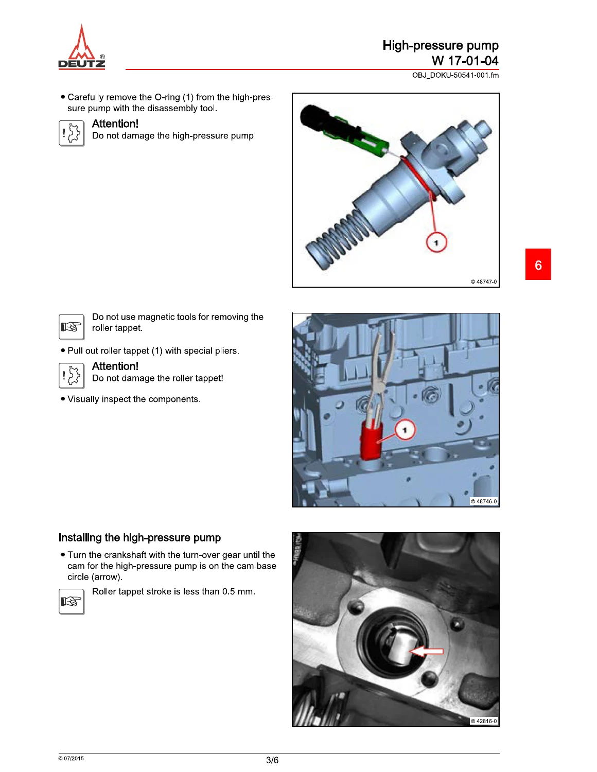
- High-pressure pump removal and installation
- Injector removal and installation
- Fuel-pump service procedures
- Fuel-pipe and connection work
- Charge-air system
- Charge-air line and related connection procedures
- Cooling system
- Coolant-pump service
- Coolant-pipe removal and installation
- Thermostat-housing procedures
- Fan-bearing service and tightening data
- Exhaust and emission-related components
- Exhaust-pipe service work
- Exhaust-gas recirculation component procedures
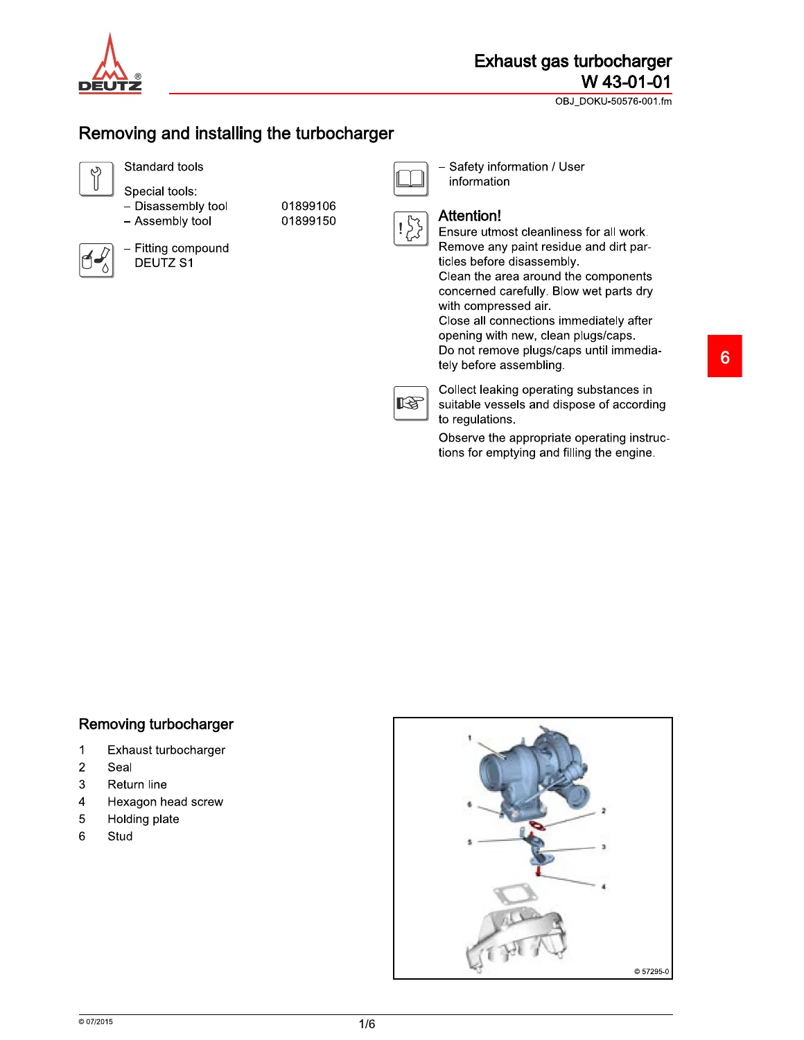
- Exhaust-gas turbocharger removal and installation
- Exhaust-gas post-treatment related procedures
- Electrical and accessory components
- Generator-related service information
- Electrical-equipment component procedures
- Protective caps, connections and associated hardware
- Start-aid components
- Sensors and electrical reference data
- Temperature-sensor procedures
- Electrical pin-assignment information
- Special tools
- Tool identification and application information used throughout the workshop procedures
The breadth of these job cards makes this much more than a basic engine overview. The manual follows the TCD 6.1 L6 4V from major mechanical components such as the crankcase, crankshaft, pistons, connecting rods and cylinder head through fuel injection, lubrication, cooling, turbocharging, exhaust-gas systems, electrical components and sensors. The repeated use of exploded illustrations and component callouts helps identify exactly what must be removed, renewed, measured or positioned during each operation.
Illustrated Removal and Installation Procedures
A major strength of the Deutz TCD 6.1 L6 4V Fendt 700 Vario S4 Workshop Service Manual PDF is its step-by-step pictorial format. Job cards frequently begin with the standard or special tools required, followed by numbered component lists and a defined sequence for dismantling. The corresponding installation section then shows preparation of sealing surfaces, replacement of seals or sealing rings where specified, positioning of components, tightening operations and final checks.
Examples visible throughout the manual include crankcase-breather work, crankshaft sealing-ring replacement, front-cover installation, piston cooling-nozzle procedures, high-pressure-pump work and turbocharger removal and installation. The illustrations distinguish individual bolts, pipes, clips, sealing rings and assemblies so that the written steps can be followed against the actual component layout.
Inspection, Measurement and Service Limits
The manual also provides measurement-based workshop procedures rather than relying only on visual inspection. Cylinder running surfaces are checked at specified measuring positions, while crankshaft, bearing, connecting-rod, piston, camshaft and valve-train procedures use dedicated measuring equipment and defined checking points. Where applicable, the job cards are followed by technical-data sections containing testing, setting or dimensional information.
This is particularly useful during overhaul work, where determining whether a component can be reused is just as important as knowing how to remove it. The manual illustrates measuring tools, measurement orientation and component locations so technicians can reproduce the specified checking method instead of estimating condition by appearance alone.
Tightening Specifications and Assembly Information
Numerous procedures include tightening specifications directly alongside the relevant assembly step, and dedicated technical-data tables provide additional values for bolts, covers, pipes, housings and engine components. Some assemblies use staged tightening instructions, while others specify particular sealing compounds, packing compounds, lubricants or replacement seals.
IMAGES PREVIEW
The service information therefore supports the critical reassembly stage after engine repair. Correct component orientation, correct seal installation, defined fastener tightening and the prescribed sequence all matter when working on major engine assemblies, fuel-system components, oil circuits, cooling-system parts and turbocharger connections.
Fuel Injection, Air Handling and Exhaust Systems
The fuel-system job cards cover the high-pressure pump, injectors, fuel pump and associated fuel pipes and connections. Illustrated procedures identify fittings and component locations and include the cleanliness and safety precautions required for work around the fuel system.
Air and exhaust-related sections extend the repair coverage into charge-air components, exhaust piping, exhaust-gas recirculation and the exhaust-gas turbocharger. Turbocharger procedures show the assembly and its surrounding oil, coolant or air connections as applicable to each job card, helping the technician identify what must be disconnected before the unit is removed and what must be restored during installation.
Safety and Workshop Information
The opening sections provide DEUTZ workshop safety and user information covering general repair precautions, work on fuel systems, electrical and electronic equipment, lubricants and other operating materials. The manual explains the job-card structure and symbols used for danger, caution, notes, tools, working materials, reference information, test and setting data and tightening specifications. This makes the later repair instructions easier to interpret consistently.
Repair the TCD 6.1 L6 4V with the Correct Workshop Procedures
The Deutz TCD 6.1 L6 4V Fendt 700 Vario S4 Workshop Service Manual PDF gives technicians a practical reference for engine dismantling, inspection, component replacement and accurate reassembly. It can support work ranging from seals, covers, pipes and external accessories through crankshaft, piston, cylinder-head, fuel-injection, cooling, lubrication, turbocharger and exhaust-system repairs. The combination of illustrated job cards, measurement procedures, special-tool information and tightening specifications helps reduce guesswork and makes it easier to perform repairs according to the procedures and values shown in the manual.
Delivered as an instant PDF download after purchase, there is no physical book and no shipping delay. The manual can be viewed on compatible computers, tablets and phones and pages can be printed when a paper workshop reference is more convenient.
Reviews
There are no reviews yet.