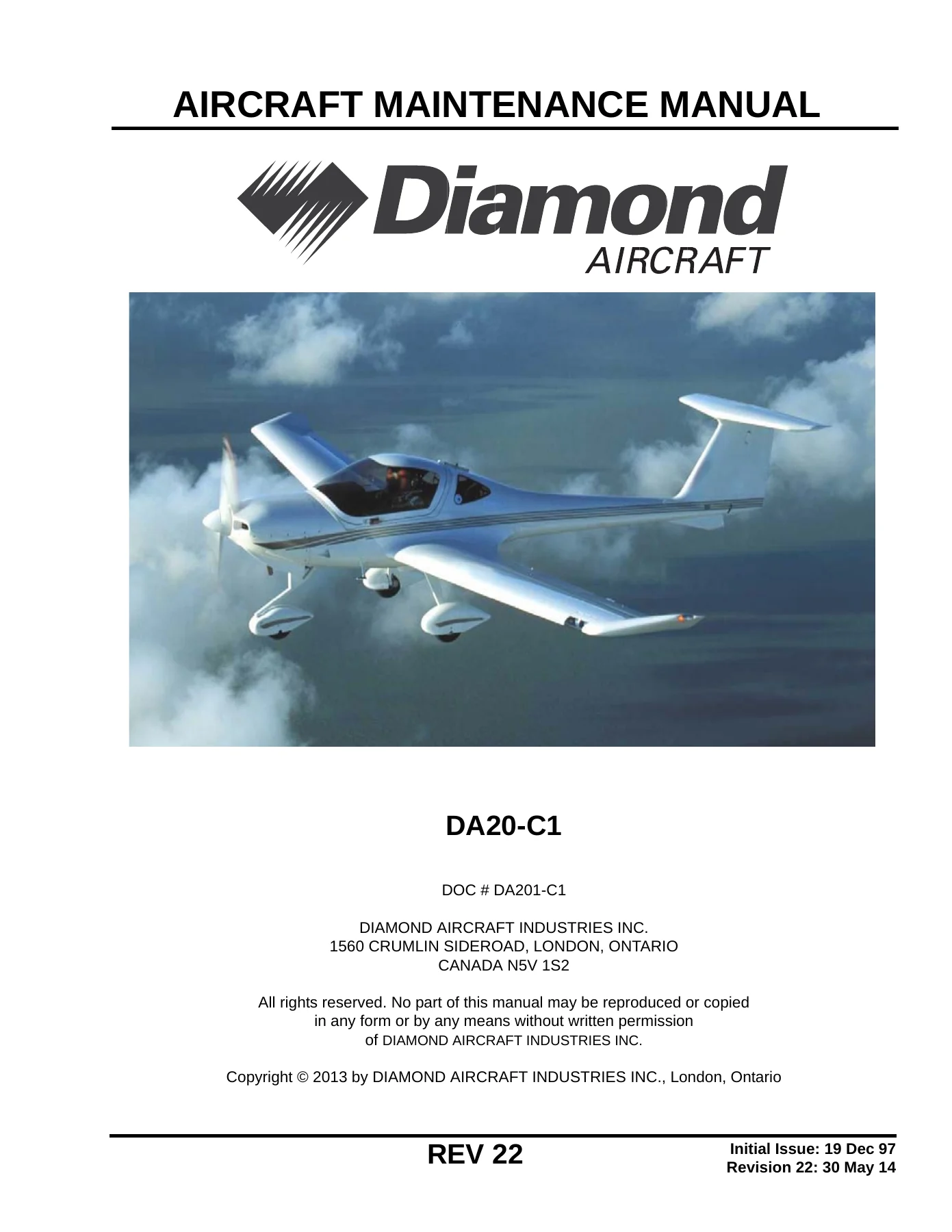
Diamond DA20-C1 Aircraft Maintenance Manual DA201-C1 Rev 22 – PDF Download
$49.95 Original price was: $49.95.$29.95Current price is: $29.95.
The complete Diamond DA20-C1 Aircraft Maintenance Manual, document DA201-C1 at Revision 22. ATA-formatted coverage of the airframe, Teledyne Continental IO-240-B engine, avionics, landing gear, flight controls, structures and wiring diagrams for the DA20-C1 aeroplane.
Description
Diamond DA20-C1 Aircraft Maintenance Manual DA201-C1 Rev 22 is the full ATA Spec 2200-formatted Aircraft Maintenance Manual (AMM) for the Diamond DA20-C1 single-engine, two-seat composite aeroplane. Published by Diamond Aircraft Industries Inc. of London, Ontario, Canada, this Revision 22 edition carries the document number DA201-C1 and is written in AECMA Simplified English so that every inspection step, torque value and adjustment figure reads unambiguously. It is the manual a maintenance shop reaches for when servicing, inspecting, fault-isolating, removing, installing, testing, adjusting or repairing the DA20-C1 airframe and its systems.
File Details
- Manual type: Aircraft Maintenance Manual (AMM), ATA Spec 2200 chapter numbering
- Manufacturer: Diamond Aircraft Industries Inc., London, Ontario, Canada
- Aircraft model: DA20-C1
- Document number: DA201-C1
- Revision: Rev 22, dated 30 May 2014
- Engine covered: Teledyne Continental IO-240-B
- Language: English (AECMA Simplified English)
- File format: PDF
- Pages: 1372
Chapters Covered
- 01-00-00 Introduction – general, revision service, warnings/cautions/notes, manual configuration, page numbering system, figures, record of revisions, list of effective pages, service bulletins, safety, acronyms, manual change request form
- 02-00-00 Organization and Handling of the Manual – applicability, revisions, temporary revisions, service bulletins, service instructions, abbreviations, conversion factors, torque conversion graphs
- 03-00-00 General Description of the Aircraft – description, equipment data with supplier addresses
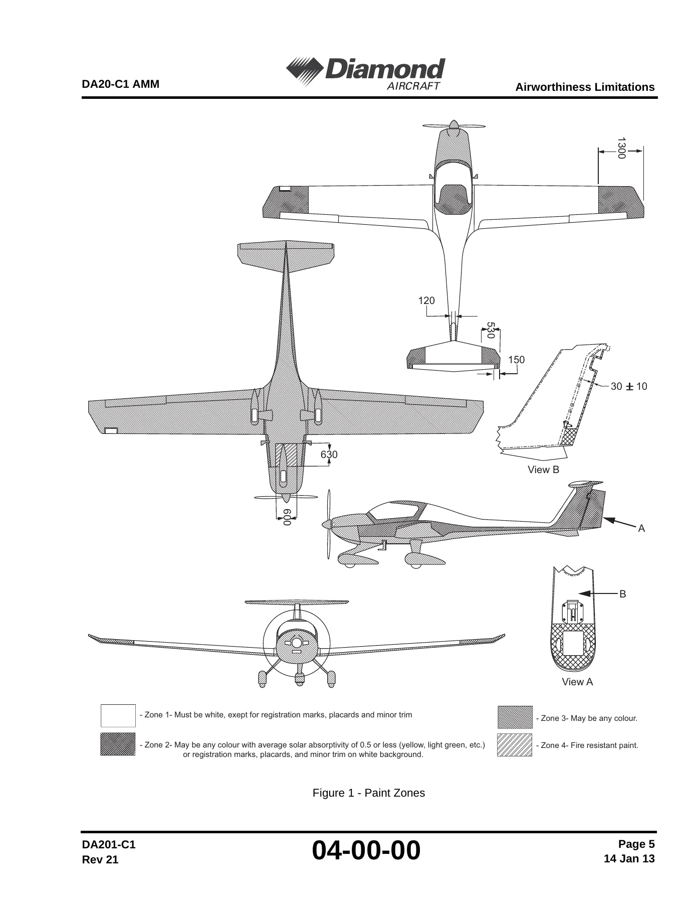
- 04-00-00 Airworthiness Limitations – paint zones, aircraft life limited components, component life tracking
- 05-00-00 Time Limits and Maintenance Checks – time limits, scheduled maintenance checks, 6000 hour inspection, maintenance practices, flightline checks, unscheduled maintenance checks
- 06-00-00 Dimensions and Areas – dimensions, adjustment values, control surface gaps, weight and static moments of control surfaces
- 07-00-00 Lifting and Shoring – jacking
- 08-00-00 Leveling and Weighing – weighing, leveling
- 09-00-00 Towing and Taxiing – towing procedure, taxiing procedure
- 10-00-00 Parking, Mooring, Storage and Return to Service
- 11-00-00 Placards and Markings – exterior placards and markings, interior placards and markings
- 12-00-00 Servicing – replenishing (fuel, engine oil, brake, tires), scheduled servicing and lubrication schedule, unscheduled servicing and ice/snow removal
- 20-00-00 Standard Practices – Airframe – bolt and nut types, standard torque values, special torque values, torque measurement
- 21-00-00 Heating and Ventilation – cabin heat system, cold air system, equipment cooling, heat control valve and distribution box
- 23-00-00 Communications – speech communication, audio integrating, static discharging and bonding
- 24-00-00 Electrical Power – DC generation, battery system, external power unit (EPU) system, DC electrical load distribution
- 25-00-00 Equipment/Furnishings – flight compartment, emergency, emergency locator transmitter (ELT)
- 26-00-00 Fire Protection
- 27-00-00 Flight Controls – ailerons and tabs, rudder and tab, elevator, elevator trim, flaps
- 28-00-00 Fuel – fuel storage, fuel distribution, fuel indicating
- 31-00-00 Indicating Systems – instrument and control panels, independent instruments, warning systems, Aspen EFD1000, Garmin G500 integrated display system, Traffic Advisory System (TAS) 600
- 32-00-00 Landing Gear – main landing gear, nose landing gear, wheels and brakes
- 33-00-00 Lights – cockpit lighting, exterior lights
- 34-00-00 Navigation – flight environment data, attitude and direction, landing and taxiing aids, dependent position determining
- 37-00-00 Vacuum – vacuum distribution, vacuum indicating
- 51-00-00 Standard Practices – Structures – structural classification, design and wear limits, repair limitations, inspection techniques, approved materials and suppliers, resin handling, bonding of fiber reinforced plastics, curing, control surface balancing
- 52-00-00 Doors – canopy, access panels
- 53-00-00 Fuselage – fuselage shells, firewall, T-panel, floor, forward and aft control bulkheads, center tunnel, spar bridge, seat back, rollbar, ring bulkheads, vertical stabilizer structure
- 55-00-00 Stabilizers – horizontal stabilizer, elevator, lower fin, rudder and tab
- 56-00-00 Windows – repair of the canopy transparency, replacement of the rear window
- 57-00-00 Wings – wing structure, wing attachment bolts, flaps, ailerons
- 61-00-00 Propeller – propeller assembly, Sensenich W69EK7-63, W69EK7-63G and W69EK-63 installation
- 71-00-00 Power Plant – description and operation, engine specifications, cowling, mounts, air intakes, engine drains
- 72-00-00 Engine – Teledyne Continental IO-240-B description
- 73-00-00 Engine Fuel and Control – induction air filter, fuel pressure sensor and indicator, engine fuel system bleeding procedure
- 74-00-00 Ignition – ignition switch test and removal/installation, ignition switch cables, spark plug leads
- 75-00-00 Air Cooling – baffles and winter kit baffles
- 76-00-00 Engine Controls – throttle, mixture and alternate air bowden cables, throttle/mixture and alternate air range of movement tests
- 77-00-00 Engine Indicating – RPM indicator and flexible drive, CHT and EGT thermocouple probes and indicators, Tanis engine preheat system
- 78-00-00 Exhaust – exhaust system, muffler and heat exchanger
- 79-00-00 Oil Systems – engine oil filter, oil cooler, vernatherm valve, oil temperature and pressure sensors, events switch, indicators, air/oil separator and vent
- 80-00-00 Starting – starting vibrator battery test and removal/installation
- 92-00-00 Wiring Diagrams – system wiring diagrams/schematics and avionics wiring diagrams/schematics
Read together, these chapters give a technician a complete working picture of the DA20-C1. The document opens by fixing the rules of the airframe itself – airworthiness limitations, component life tracking, paint zone restrictions, maintenance intervals and the published dimensions and control surface gaps – before moving into the practical systems chapters. Each of those follows a consistent pattern of description and operation, a troubleshooting table of symptom, probable cause and repair, and maintenance practices that spell out access, removal/installation, adjustment, testing, cleaning, repair and the associated torque or clearance values. Structural content is handled separately under the composite practices chapter, which covers the restricted repair areas, the tap test and light test inspection methods, approved resins, glass and carbon cloth, fillers, bonding paste mixtures and the post-cure schedule used on this airframe.
Serial Number Applicability
Several systems and installations in this manual are tied to aircraft serial number, and the text marks those differences inline rather than burying them. The external power receptacle location, for example, is given separately for C0001 through C0148 and C0150, and for C0149 and C0151 onwards, with different relay removal procedures for each. Battery forward electrical schematics are split between C0001 and later production, and between C0648 and up. Placard figure sets distinguish panels up to S/N 0149 from S/N 0150 and subsequent aircraft. Ignition switch procedures are also split between pre-SB DAC1-74-03 Rev 2 and post-SB DAC1-74-03 Rev 2 configurations. Checking the applicability note before starting a task is a normal part of using this manual.
Avionics, Instrument Panels and Optional Equipment
The AMM deliberately documents more than the baseline aircraft, which is why the communications, indicating and navigation chapters run long. Covered installations include the Bendix/King KX 125 and KX 155 NAV COMM, KLX 135/135A GPS COMM, KLN 35A GPS, KT 76A and KI 208/209 indicators, the Bendix/King KMA 24 audio/marker receiver, Garmin GNS430W, GNS530W, GNC 420W, GTN 650 and GTR 225, Garmin GTX 327, GTX 328 and GTX 330 transponders, the GMA 340 and GMA 340H audio panels, SL40 and IC-A200 transceivers, PM 501 and PM 1000 intercoms, the Aspen EFD1000 electronic flight instrument system, the Garmin G500 integrated display system and the optional TAS 600 traffic advisory system. Standard, reversed and G500 instrument panel layouts are illustrated, as are the placard sets that go with each. The wiring diagram chapter at the back ties these together with system schematics and avionics interconnect drawings.
What You Can Do With This Manual
The maintenance schedule in Chapter 05 drives the day-to-day workload: 25, 50, 100, 200, 1000 and 6000 hour checks plus annual inspection, each broken down into zone-by-zone inspection items with the applicable interval marked, followed by the engine ground test, maintenance report, maintenance check flight report and engine ground test record forms. The unscheduled maintenance chapter then covers the situations nobody plans for – hard landing inspection areas, propeller strike, hydraulic lock and engine fire – and tells you what to examine and in what order. Chapter 20 provides the standard and special torque values, including the propeller, engine mount, landing gear and exhaust figures, so fasteners go back on correctly rather than approximately.
Beyond the schedule, this DA20-C1 AMM supports real repair work. Composite damage assessment and repair is covered with the restricted area diagrams showing where external skin damage up to 250 mm or 50 mm may be repaired and where only the manufacturer or an approved repair facility may work. Bonding paste mix ratios, resin-to-hardener tables, pre-cure and post-cure times are all printed. Control surface weighing and balancing procedures are given for the rudder, elevator, aileron and flap, with the reminder that any repair, paint or reported in-flight control vibration requires re-balancing before flight. Landing gear, wheels and brakes, fuel storage and distribution, electrical generation and distribution, vacuum instruments, canopy latch force adjustment and stall warning maintenance are all documented with the access notes and safety warnings that accompany them.
Why Correct Procedures Matter Here
The DA20-C1 is a composite airframe with carbon fiber spar caps, a spar bridge that carries wing and landing gear loads, and control surfaces whose balance is critical to flutter prevention. Working from manufacturer procedures rather than assumption is what keeps those structures and systems within their limits. This manual states the wear limits, the fit tolerances on wing attachment bolts, the radial and axial play allowances, the bleed and leak test figures, the pitot and static leak acceptance rates and the flap pre-load values, so an inspection produces a defensible result rather than a guess.
Complete Bookmarks
The complete bookmarks in the βDiamond DA20-C1 Aircraft Maintenance Manual DA201-C1 Rev 22 – PDF Downloadβ are as follows:
+DA20-C1 – AIRCRAFT MAINTENANCE MANUALp. 1
+FrontMatterp. 1
+CHAPTER 01-00 INTRODUCTIONp. 49
+INTRODUCTIONp. 53
+4. Manual Configurationp. 54
+CHAPTER 02-00 ORGANIZATION AND HANDLING OF THE MANUALp. 61
+ORGANIZATION AND HANDLING OF THE MANUALp. 65
+CHAPTER 03-00 GENERAL DESCRIPTION OF THE AIRCRAFTp. 73
+GENERAL DESCRIPTION OF THE AIRCRAFTp. 77
+CHAPTER 04-00 AIRWORTHINESS LIMITATIONSp. 81
+Airworthiness Limitations
+1. Generalp. 87
+CHAPTER 05-00 TIME LIMITS AND MAINTENANCE CHECKSp. 91
+Time Limits and Maintenance Checksp. 95
+2. Chapter Configurationp. 95
+05-10 – Time Limitsp. 97
+05-20 – Scheduled Maintenance Checksp. 99
+2. Maintenance Checklistp. 99
+3. 6000 Hour Inspectionp. 100
+Maintenance Practicesp. 103
+4. Maintenance of Checklist Zonesp. 105
+05-30 – Flightline Checksp. 141
+05-50 – Unscheduled Maintenance Checksp. 143
+2. Hard Landing Checkp. 143
+4. Hydraulic Lockp. 145
+CHAPTER 06-00 DIMENSIONS AND AREASp. 151
+Dimensions and Areasp. 155
+1. Generalp. 155
+CHAPTER 07-00 LIFTING AND SHORINGp. 163
+Lifting and Shoringp. 167
+07-10- Jackingp. 169
+2. Lifting the Aircraft on the Jacksp. 169
+CHAPTER 08-00 LEVELING AND WEIGHINGp. 173
+Leveling and Weighingp. 177
+08-10 – Weighingp. 179
+2. Weighingp. 179
+08-20 – Levelingp. 185
+2. Make the Aircraft Level with Jacksp. 185
+CHAPTER 09-00 TOWING AND TAXIINGp. 189
+Towing and Taxiingp. 193
+09-10 – Towingp. 195
+3. Towing Procedurep. 196
+09-20 – Taxiingp. 199
+CHAPTER 10-00 PARKING, MOORING, STORAGE AND RETURN TO SERVICEp. 201
+Parking, Mooring, Storage and Return to Servicep. 203
+10-10 – Parking/Storagep. 207
+2. Parkingp. 207
+3. Storagep. 208
+10-20 – Mooringp. 211
+2. Mooringp. 211
+10-30 – Return to Servicep. 213
+CHAPTER 11-00 PLACARDS AND MARKINGSp. 215
+Placards and Markingsp. 219
+2. Replace the Plastic Foil Placardsp. 219
+11-20 – Exterior Placards and Markings
+11-30 – Placards and Markings
+CHAPTER 12-00 SERVICINGp. 241
+Servicingp. 245
+12-010 – Replenishingp. 247
+2. Fuel Systemp. 247
+3. Engine Oil Systemp. 250
+4. Brake Systemp. 252
+5. Tiresp. 252
+12-20 – Scheduled Servicingp. 253
+12-30 – Unscheduled Servicingp. 261
+CHAPTER 20-00 STANDARD PRACTICES AIRFRAMEp. 263
+Standard Practices – Airframep. 267
+3. Standard Torque Valuesp. 268
+CHAPTER 21-00 AIR CONDITIONINGp. 273
+Heating and Ventilationp. 277
+2. Description and Operationp. 277
+Heating and Ventilation – Troubleshootingp. 281
+Heating and Ventilation – Maintenance Practicesp. 283
+2. Remove/Install the Heat Control Valvep. 283
+4. Remove/Install the Distribution Boxp. 285
+6. Remove/Install the Heat Exchanger Shroudp. 291
+8. Remove/Install the Avionics Cooling Fanp. 294
+CHAPTER 23-00 COMMUNICATIONSp. 297
+Communications
+2. Description
+23-10 – Speech Communicationp. 303
+2. Descriptionp. 304
+Speech Communication – Troubleshootingp. 319
+Speech Communication – MAINTENANCE PRACTICESp. 321
+2. Remove/Install the Bendix/King KX-125 NAV COMMp. 321
+3. Remove/Install the Bendix\King KLX 135/135A GPS COMMp. 323
+4. Remove/Install the Garmin GNC 420W/GNS 430W/GTN 650p. 325
+5. Remove/Install the Garmin GNS530Wp. 327
+6. Remove/Install the Bendix/King KX155 NAV COMMp. 329
+7. Remove/Install the IC-A200 VHF Air Band Transceiverp. 331
+8. Remove/Install the SL40/GTR 225VHF COMM Transceiverp. 333
+23-50 – Audio Integratingp. 337
+2. Descriptionp. 337
+Audio Integrating – Troubleshootingp. 343
+1. Generalp. 343
+Audio Integrating – Maintenance Practicesp. 345
+2. Remove/Install the PM 501 Intercomp. 345
+3. Remove/Install the PM 1000 Intercomp. 346
+4. Remove/Install the Bendix\King KMA 24 Audio/Marker Receiverp. 348
+5. Remove/Install the GMA 340 Audio Panelp. 350
+23-60 – static dischargingp. 355
+Static Discharging – MAINTENANCE PRACTICESp. 357
+2. Repair/Install the New Copper Tapep. 357
+3. Replace/Install the New Bonding Tabsp. 358
+CHAPTER 24-00 ELECTRICAL POWERp. 359
+Electrical Powerp. 363
+24-30 – DC Generationp. 367
+2. Description and Operationp. 367
+DC Generation – troubleshootingp. 371
+DC Generation – Maintenance Practicesp. 377
+3. Remove/Install the Over Voltage Sensorp. 377
+4. Adjust/Test the Over Voltage Sensorp. 378
+5. Remove/Install the Generator/Alternator Mounting Bracketp. 379
+6. Remove/Install the Generator/Alternatorp. 383
+7. Adjust/Test the Generator/Alternatorp. 385
+24-31 – Battery Systemp. 389
+Battery System – Troubleshootingp. 393
+Battery System – Maintenance Practicesp. 395
+3. Batteryp. 396
+4. Remove/Install the Battery Relayp. 398
+5. Remove/Install the Battery Relay on the Firewallp. 399
+6. Remove/Install the Ammeter
+7. Remove/Install the Voltmeter
+24-40 – External Power Unit (EPU) Systemp. 405
+EPU System – Maintenance Practicesp. 409
+3. Remove/Install the EPU Relay to C0001 through C0148 and C0150p. 409
+4. Remove/Install the EPU Relay to C0149 and C0151 onwardsp. 411
+epu system – troubleshootingp. 407
+24-60 – DC Electrical Load Distributionp. 413
+2. Descriptionp. 413
+DC electrical load distribution – troubleshootingp. 419
+DC Electrical Load Distribution – Maintenance Practicesp. 421
+3. Remove/Install the Avionic Master Relayp. 421
+4. Remove/Install a Circuit-breakerp. 422
+CHAPTER 25-00 EQUIPMENT/FURNISHINGp. 425
+Equipment/Furnishingp. 429
+25-10 – Flight Compartmentp. 431
+2. Descriptionp. 431
+Equipment/F urnishing – Maintenance Practicesp. 433
+2. Remove/Install a Pilotβs Seatp. 433
+3. Remove/Install a Safety Beltp. 435
+4. Remove/Install the Instrument Panel Coverp. 437
+5. Remove/Install the Baggage Compartment Floor Panelp. 437
+6. Cleaningp. 438
+25-60 – Emergencyp. 439
+ELT – Maintenance Practicesp. 441
+25-60 – ME 406 Emergency Locator Transmitter (ELT)p. 443
+2. Descriptionp. 443
+3. Operationp. 444
+ME 406 ELT – Troubleshootingp. 447
+ME 406 ELT – Maintenance Practicesp. 449
+2. Remove/Install the ELTp. 449
+CHAPTER 26-00 FIRE PROTECTIONp. 455
+Fire Protectionp. 459
+CHAPTER 27-00 FLIGHT CONTROLSp. 461
+Flight Controlsp. 467
+Flight Controls – Maintenance Practicesp. 469
+2. Remove/Install the Control Stickp. 469
+27-10 – Flight Controls – Ailerons and Tabsp. 473
+Aileron Control – Troubleshootingp. 477
+Aileron Control – Maintenance Practicesp. 479
+2. Aileron Control System Test For Correct Range Of Movementp. 479
+3. Aileron Control System Adjustmentsp. 481
+27-20 – Flight Controls – Rudder and Tabp. 487
+Rudder Control – Troubleshootingp. 493
+Rudder Control – Maintenance Practicesp. 495
+2. Rudder Control System Test for Correct Range Of Movementp. 495
+3. Rudder Control System Adjustmentsp. 496
+4. Remove/Install Rudder Control Cablesp. 498
+27-30 – Flight Controls – Elevatorp. 503
+Elevator Control – Troubleshootingp. 505
+Elevator Control – Maintenance Practicesp. 507
+2. Elevator Control System Test for Correct Range of Movementp. 507
+3. Elevator Control System Adjustmentsp. 508
+27-31 – Flight Controls – Elevator Trimp. 511
+Elevator Control Trim – Troubleshootingp. 515
+Elevator Trim – Maintenance Practicesp. 517
+2. Remove/Install the Elevator Trim Actuatorp. 517
+27-50 – Flight Controls – Flapsp. 521
+2. Descriptionp. 521
+Flaps – Troubleshooting
+Flaps – Maintenance Practicesp. 533
+2. Remove/Install the Flap Actuatorp. 533
+3. Adjust/Test the Flap Systemp. 534
+CHAPTER 28-00 FUELp. 541
+Fuelp. 545
+28-10- – Fuel Storagep. 549
+Fuel Storage – Troubleshootingp. 551
+Fuel Storage – Maintenance Practicesp. 553
+2. Remove/Install the Fuel Tankp. 553
+3. Remove/Install the Fuel Filler Neckp. 555
+28-20 – Fuel Distributionp. 561
+2. Descriptionp. 561
+Fuel Distribution – Troubleshootingp. 565
+Fuel Distribution – Maintenance Practicesp. 567
+2. Remove/Install the Electric Fuel Pumpp. 567
+3. Remove/Install the Fuel Shut-Off Valvep. 570
+28-40 – Fuel Indicatingp. 575
+Fuel Indicating – Troubleshooting
+Fuel Indicating – Maintenance Practicesp. 581
+2. Remove/Install the Fuel Quantity Sensorp. 581
+6. Remove/Install the Fuel Quantity Gaugep. 585
+CHAPTER 31-00 INDICATING SYSTEMSp. 589
+Indicating Systemsp. 595
+31-10 – Instrument and Control Panelsp. 597
+2. Descriptionp. 597
+Instrument and Control Panels – Troubleshootingp. 609
+Instrument and Control Panels – Maintenance Practicesp. 611
+2. Remove/Install the Instrument Panelp. 611
+3. Remove/Install the Control Panelp. 615
+31-20 – Independent Instrumentsp. 619
+2. Description and Operationp. 619
+Independent Instruments – Troubleshootingp. 621
+Independent Instruments – Maintenance Practicesp. 623
+2. Remove/Install the Clockp. 623
+3. Remove/Install the Engine Operated Hourmeterp. 624
+31-50 – Warning Systemsp. 625
+Warning Systems – Troubleshootingp. 627
+Warning Systems – Maintenance Practicesp. 629
+2. Remove/Install a Warning Lamp Bulbp. 629
+3. Remove/Install an Annunciator Unitp. 630
+31-60 – Aspen EFD1000p. 631
+2. Descriptionp. 631
+3. Operationp. 634
+Aspen EFD1000 – Troubleshootingp. 641
+1. Generalp. 641
+Aspen EFD1000 System – Maintenance Practicesp. 645
+2. Remove/Install the Primary Flight Display (PFD)p. 645
+3. Remove/Install the Remote Sensor Module (RSM)p. 648
+4. Remove/Install the Configuration Module (CM)p. 650
+5. Remove/Install the Analog Converter Unit (ACU)p. 651
+31-61 – Garmin G-500 Integrated Display Systemp. 655
+2. Description and Operationp. 655
+Garmin G500 – Troubleshootingp. 663
+Garmin G500 – Maintenance Practicesp. 669
+2. Remove/Install the GDU 620 Displayp. 669
+3. Remove/Install the GDC 74A Air Data Computer (ADC)p. 671
+4. Remove/Install the GRS77 Attitude, Heading and Reference Unit (AHRS)p. 672
+5. Remove/Install the GMU 44 Magnetometerp. 673
+6. Remove/Install the Temperature Probe (GTP 59)p. 674
+31-62 – Traffic Advisory System (TAS) 600 – Troubleshootingp. 679
+Traffic Advisory System (TAS) 600p. 681
+3. Operationp. 682
+Traffic Advisory System (TAS) 600 – Maintenance Practicesp. 685
+2. Remove/Install the TAS 600 Processor Unitp. 685
+3. Remove/Install the TAS Transponder Couplerp. 687
+4. Remove/Install the TAS Antennap. 688
+CHAPTER 32-00 LANDING GEARp. 691
+Landing Gearp. 695
+32-10 – Main Landing Gearp. 697
+Main Landing Gear – Troubleshootingp. 699
+Main Landing Gear – Maintenance Practicesp. 701
+2. Remove/Install the Main Landing Gearp. 701
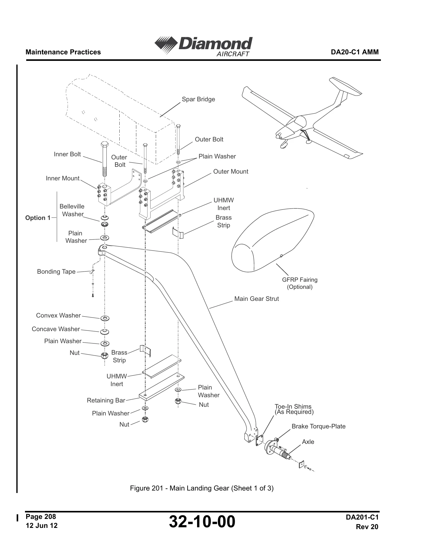
+3. Remove/Install the Hardware at the Inner and Outer Mounts of the Main Landing-Gear Strutp. 704
+4. Test/Adjust the Main Landing Gearp. 706
+32-20 – Nose Landing Gearp. 713
+Nose Landing Gear – Troubleshootingp. 715
+Nose Landing Gear – Maintenance Practicesp. 717
+2. Remove/Install the Nose Landing Gear (NLG)p. 717
+3. Remove/Install the NLG Fork Assemblyp. 720
+4. Remove/Install the Shock Absorber Assemblyp. 721
+6. Adjust the Nose Landing Steering Frictionp. 724
+32-40 – Wheels and Brakesp. 731
+2. Description and Operationp. 731
+Wheels and Brakes – Troubleshootingp. 737
+Wheels and Brakes – Maintenance Practicesp. 739
+2. Remove/Install the Main Wheelp. 739
+3. Remove/Install the Nose Wheelp. 741
+4. Remove/Install a Brake Master Cylinderp. 743
+5. Remove/Install a Brake Caliperp. 744
+6. Remove/Install the Parking Brake Valvep. 745
+7. Bleed the Brake Systemp. 746
+9. Wheels and Brakes Cleaning Proceduresp. 748
+CHAPTER 33-00 LIGHTSp. 753
+Lightsp. 757
+33-20 – Cockpit Lightingp. 759
+2. Descriptionp. 759
+Cockpit Lighting – Troubleshootingp. 761
+Cockpit Lighting – Maintenance Practicesp. 763
+2. Remove/Install the General Instrument Light/Map Light Modulep. 763
+33-40 – Exterior Lightsp. 765
+2. Descriptionp. 765
+Exterior Lights – Troubleshootingp. 767
+Exterior Lights – Maintenance Practicesp. 769
+2. Remove/Install the Taxi Lightp. 769
+3. Remove/Install the Landing Lightp. 770
+6. Remove/Install The Light Unit In The Wing Tipp. 773
+7. Remove/Install the Power Unit for the Anti-Collision Lightsp. 775
+CHAPTER 34-00 NAVIGATIONp. 781
+Navigationp. 787
+2. Descriptionp. 787
+34-10 – Flight Environment Datap. 789
+2. Descriptionp. 789
+Flight Environment Data – Troubleshootingp. 793
+1. Generalp. 793
+Flight Environment Data – Maintenance Practicesp. 801
+2. Remove/Install a Pitot-Static Instrumentp. 801
+3. Remove/Install Pitot-Static Probe (probe without optional Pitot Heat)p. 802
+4. Remove/Install and Functional Check of the Pitot-Static Probe (Probe with optional Pitot Heat System).p. 803
+5. Remove/Install the Blind Altitude Encoderp. 805
+6. Remove/Install the OAT Indicatorp. 807
+7. Pitot and Static Leak Testsp. 808
+34-20 – Attitude and Directionp. 811
+2. Description and Operationp. 811
+Attitude and Direction – Troubleshootingp. 817
+Attitude and Direction – Maintenance Practicesp. 819
+2. Remove/Install the Magnetic Compassp. 819
+3. Test/Adjust the Magnetic Compassp. 820
+4. Remove/Install the Stall Warning Horn Assemblyp. 821
+6. Remove/Install the Backup Artificial Horizon Indicatorp. 823
+34-30 – Landing and Taxiing Aidsp. 825
+Landing and Taxiing Aids – Troubleshootingp. 827
+Landing and Taxiing Aids – Maintenance Practicesp. 829
+2. Remove/Install the Bendix\King KMA 24 Audio/Marker Receiverp. 829
+34-50 – Dependent Position Determiningp. 833
+2. Description and Operationp. 834
+Dependent Position Determining – Troubleshootingp. 857
+1. Generalp. 857
+Dependent Position Determining – Maintenance Practicesp. 859
+2. Remove/Install the Bendix\King KX 125 NAV COMMp. 859
+3. Remove/Install the Bendix\King KX 155 NAV COMMp. 861
+4. Remove/Install the Bendix\King KLN 35A GPS Receiverp. 863
+5. Remove/Install the Bendix\King KLX 135/135A GPS COMMp. 865
+6. Remove/Install the Bendix\King KI 208/209 Indicatorp. 867
+7. Remove/Install the Bendix\King KT 76A Transponderp. 868
+8. Remove/Install the GTX 327 Transponderp. 870
+9. Remove/Install the GTX 328 Transponderp. 871
+10. Remove/Install the GTX 330 Transponderp. 873
+11. Remove/Install the Garmin GNC 420W/GNS 430W/GTN 650p. 874
+12. Remove/Install the Garmin GNS530Wp. 876
+13. Remove/Install the GNS 430W/GNS 530W VOR, LOC, G/S Indicatorp. 877
+CHAPTER 37-00 VACUUMp. 885
+Vacuump. 889
+2. Descriptionp. 889
+37-10 – Vacuum Distributionp. 893
+Tacuum Distribution – Troubleshootingp. 895
+Vacuum Distribution – Maintenance Practicesp. 897
+2. Remove/Install the Vacuum Pumpp. 897
+3. Remove/Install the Vacuum Regulatorp. 898
+37-10 – Vacuum Indicatingp. 903
+Vacuum Indicating – Troubleshootingp. 905
+Vacuum Indicating – Maintenance Practicesp. 907
+2. Remove/Install the Vacuum Gaugep. 907
+CHAPTER 51-00 STANDARD PRACTICES STRUCTURESp. 909
+Standard Practices – Structuresp. 913
+2. Structural Classificationp. 913
+3. Design, Dimensions, Clearances and Wear Limitsp. 915
+6. Inspection Techniquesp. 917
+7. Approved Materials and Suppliersp. 919
+8. Resin Handlingp. 921
+10. Bonding of Fiber Reinforced Plasticsp. 923
+11. Curingp. 924
+51-30 – Control Srface Balancingp. 927
+CHAPTER 52-00 DOORSp. 931
+Doorsp. 935
+52-10 – Canopyp. 937
+2. Descriptionp. 937
+3. Operationp. 938
+Canopy – Troubleshootingp. 941
+Canopy – Maintenance Practicesp. 943
+2. Remove/Install the Canopyp. 943
+3. The Canopy Latch Force Testp. 944
+6. Remove/Install the Sliding Side Windowp. 947
+52-40 – Access Panelsp. 953
+CHAPTER 53-00 FUSELAGEp. 955
+Fuselagep. 959
+53-10 – Fuselage Structurep. 961
+2. Descriptionp. 961
+Fuselage – Maintenance Practicesp. 969
+CHAPTER 55-00 STABILIZERSp. 973
+Stabilizersp. 977
+55-10 – Horizontal Stabilizerp. 979
+Horizontal Stabilizer – Maintenance Practicesp. 981
+2. Remove/Install the Horizontal Stabilizerp. 981
+55-20 – Elevatorp. 985
+Elevator – Maintenance Practicesp. 987
+2. Remove/Install the Elevatorp. 987
+55-30 – Lower Finp. 989
+Lower Fin – Maintenance Practicesp. 991
+2. Remove/Install the Lower Finp. 991
+55-40 – Rudder and Tabp. 993
+Rudder and Tab – Maintenance Practicesp. 995
+2. Remove/Install the Rudderp. 995
+3. Remove/Install the Top Pivot Bushingp. 996
+CHAPTER 56-00 WINDOWSp. 999
+Windowsp. 1003
+56-10 – Repair of the Canopy Transparencyp. 1005
+56-11 – Replacement of the Rear Windowp. 1011
+CHAPTER 57-00 WINGSp. 1015
+Wingsp. 1019
+57-10 – Wing Structurep. 1021
+2. Descriptionp. 1021
+Wing Structure – Maintenance Practicesp. 1027
+2. Remove/Install the Wingsp. 1027
+4. Bolt Playp. 1034
+57-50 – Flapsp. 1037
+2. Descriptionp. 1037
+Flaps – Maintenance Practicesp. 1039
+2. Remove/Install the Flapp. 1039
+57-60 – Aileronsp. 1043
+2. Descriptionp. 1043
+Ailerons – Maintenance Practicesp. 1045
+2. Remove/Install the Aileronp. 1045
+CHAPTER 61-00 PROPELLERp. 1047
+Propellerp. 1051
+61-10 – Propeller Assemblyp. 1053
+2. Descriptionp. 1053
+propeller assembly – troubleshootingp. 1055
+propeller Assembly – MAINTENANCE PRACTICESp. 1057
+3. Remove/Install the Sensenich Propellerp. 1057
+CHAPTER 71-00 POWER PLANTp. 1063
+Power Plantp. 1067
+2. Description and Operationp. 1069
+Power Plant – Troubleshootingp. 1073
+Power Plant – Maintenance Practicesp. 1075
+2. Remove/Install the Enginep. 1075
+71-10 – Cowlingp. 1097
+Cowling – Troubleshootingp. 1099
+Cowling – Maintenance Practicesp. 1101
+2. Remove/Install the Cowlingsp. 1101
+71-20 – Mountsp. 1107
+Mounts – Maintenance Practicesp. 1109
+2. Remove/Install the Engine Mounting Framep. 1109
+71-60 – Air Intakesp. 1113
+Air Intakes – Maintenance Practicesp. 1115
+2. Remove/Install the Air Intakep. 1115
+71-70 – Engine Drainsp. 1117
+2. Descriptionp. 1117
+Engine Drains – Troubleshootingp. 1121
+Engine Drains – Maintenance Practicesp. 1123
+2. Remove/Install the Fuel Distribution Manifold Drainp. 1123
+3. Remove/Install The Cylinder Drainp. 1124
+4. Remove/Install the Fuel Pump Drainp. 1125
+CHAPTER 72-00 ENGINEp. 1127
+Enginep. 1131
+CHAPTER 73-00 ENGINE FUEL AND CONTROLp. 1133
+Engine Fuel and Controlp. 1137
+2. Descriptionp. 1137
+Engine Fuel and Control – Troubleshootingp. 1143
+Engine Fuel and Control – Maintenance Practicesp. 1145
+2. Remove/Install the Induction Air Filterp. 1145
+3. Remove/Install the Fuel Pressure Sensorp. 1146
+4. Remove/Install the Fuel Pressure Indicatorp. 1148
+CHAPTER 74-00 IGNITIONp. 1153
+Ignitionp. 1157
+2. Description and Operationp. 1157
+Ignition – Troubleshootingp. 1161
+Ignition – Maintenance Practicesp. 1163
+3. Remove/Install the Ignition Switch (Pre-SB DAC1-74-03 Rev 2)p. 1164
+4. Remove/Install the Ignition Switch (Optional) (Post-SB DAC1-74-03 Rev 2)p. 1166
+5. Remove/Install the Ignition Switch Cablesp. 1167
+6. Remove/Install the Spark Plug Leadsp. 1169
+CHAPTER 75-00 AIRp. 1175
+Air Coolingp. 1179
+2. Descriptionp. 1179
+AIr cooling – Maintenance Practicesp. 1181
+2. Remove/Install the Bafflesp. 1181
+CHAPTER 76-00 ENGINE CONTROLSp. 1193
+Engine Controlsp. 1197
+2. Description and Operationp. 1197
+Engine Controls – Troubleshootingp. 1201
+Engine Controls – Maintenance Practicesp. 1203
+2. Remove/Install The Throttle Bowden Cablep. 1203
+3. Remove/Install the Mixture Control Bowden Cablep. 1209
+4. Remove/Install the Alternate Air Control Bowden Cablep. 1216
+5. Throttle/Mixture Control Range Of Movement Testp. 1223
+CHAPTER 77-00 ENGINE INDICATINGp. 1231
+Engine Indicatingp. 1235
+2. Descriptionp. 1235
+Engine Indicating – Troubleshootingp. 1239
+Engine Indicating – Maintenance Practicesp. 1241
+2. Remove/Install the RPM Indicatorp. 1241
+3. Remove/Install the RPM Indicator Flexible Drivep. 1242
+4. Remove/Install the Cylinder Head Temperature (CHT) Thermocouple Probep. 1244
+5. Remove/Install the Exhaust Gas Temperature (EGT) Thermocouple Probe
+6. Remove/Install The Exhaust Gas Temperature (EGT) Indicator
+7. Remove/Install the Cylinder Head Temperature Indicator
+8. Remove/Install the Tanis Engine Preheat System (Optional)p. 1249
+CHAPTER 78-00 EXHAUSTp. 1251
+Exhaustp. 1255
+Exhaust – Troubleshootingp. 1257
+Exhaust – Maintenance Practicesp. 1259
+2. Remove/Install the Exhaustp. 1259
+CHAPTER 79-00 OILp. 1263
+Oil Systemsp. 1267
+Oil Systems – Troubleshootingp. 1273
+Oil Systems – Maintenance Practicesp. 1275
+2. Remove/Install the Engine Oil Filterp. 1276
+3. Remove/Install the Oil Coolerp. 1277
+4. Remove/Install the Vernatherm Valvep. 1279
+5. Remove/Install the Oil Temperature Sensorp. 1280
+6. Remove/Install the Oil Pressure Sensorp. 1281
+7. Remove/Install the Events Switchp. 1282
+8. Remove/Install the Oil Pressure Indicator
+9. Remove/Install the Oil Temperature Indicator
+10. Remove/Install the Air/Oil Separatorp. 1285
+11. Remove/Install the Air/Oil Separator Ventp. 1286
+CHAPTER 80-00 STARTINGp. 1287
+Startingp. 1291
+Starting – Troubleshootingp. 1293
+Engine Starting – Maintenance Practicesp. 1295
+3. Remove/Install The Starting Vibrator Batteryp. 1295
+CHAPTER 92-00 WIRING DIAGRAMSp. 1297
+Wiring Diagramsp. 1303
+List of Wiring Diagrams/Schematicsp. 1303
IMAGES PREVIEW
Delivery is instant. The Diamond DA20-C1 Aircraft Maintenance Manual DA201-C1 Rev 22 arrives as a PDF download immediately after checkout, with no shipping and no waiting for a printed copy. Open it on a laptop, tablet or phone in the hangar, search or scroll to the chapter you need, and print the pages you want to take to the aircraft. Whether you are running a 100 hour check, chasing a generator that will not come on line, replacing a canopy latch, installing an avionics upgrade or assessing composite damage, this DA20-C1 AMM keeps the procedure and the numbers in front of you.
What Our Customers Say
π Related Products
Discover more professional manuals for your equipment

Airbus A318 A319 A320 A321 AMM Chapter 11 Placards and Markings AES Revision 40 May 2012

Airbus A318 A319 A320 A321 Servicing Manual Chapter 12 - AES Rev 40 (2012) PDF

Pipistrel Sinus 912, Virus 912, Virus SW 80/100 & ALPHA Trainer LSA Aircraft Maintenance Manual 2019


Reviews
There are no reviews yet.