
Doosan D50S-5 D90S-5 G50S-5 G70S-5 Forklift Service Manual – SB4271E 2013
Original price was: $39.95.$23.95Current price is: $23.95.
Complete 1,899-page Doosan forklift service manual covering D50S-5, D60S-5, D70S-5, D80S-5, D90S-5, G50S-5, G60S-5 and G70S-5 models with DB58S, D439E, V3800 diesel and G643(E) LP engines. Form SB4271E, October 2013.
Description
Doosan D50S-5 D90S-5 G50S-5 G70S-5 Forklift Service Manual – Complete Workshop Reference
This Doosan D50S-5 D90S-5 G50S-5 G70S-5 forklift service manual is the comprehensive workshop reference for maintaining, diagnosing and repairing the complete range of Doosan counterbalanced lift trucks covered by form number SB4271E. Published in October 2013, this 1,899-page PDF manual brings together detailed service information for every major system on the D50S-5, D60S-5, D70S-5, D80S-5, D90S-5, G50S-5, G60S-5 and G70S-5 models, including full coverage of the DB58S, D439E and V3800 diesel engines plus the G643(E) LP engine. Whether you are servicing a single truck or managing a fleet, this manual provides the specifications, torque values and step-by-step procedures needed to carry out everything from routine maintenance to complete engine and transmission overhauls.
File Details
- Manual type: Compiled Service Manual
- Brand: Doosan
- Covered models: D50S-5, D60S-5, D70S-5, D80S-5, D90S-5, G50S-5, G60S-5, G70S-5
- Covered engines: DB58S Diesel (Tier II), D439E Diesel (Tier III), V3800 Diesel (Tier IV Interim), G643(E) LP
- Document numbers: SB4271E, SB4272E04, SB2003E01, SB2004E00, SB4261E00, SB4262E00, SB4263E01, SB4118E01, SB4323E00, SB4401E00, SB4274E02, SB4121E01, SB4122E01, SB4341E00, SB4342E00, SB4276E01, SB4277E00, SB4278E01, SB4279E03, SB4132E01, SB4280E00, SB2356E
- Publication date: October 2013
- Language: English
- Page count: 1,899
- File format: PDF
Chapters Covered
- Safety – warning plates, decals, general hazard information, operating and maintenance safety
- Torque Specifications – metric and inch standard torque tables, taperlock studs, O-ring face seal fittings, hydraulic line installation
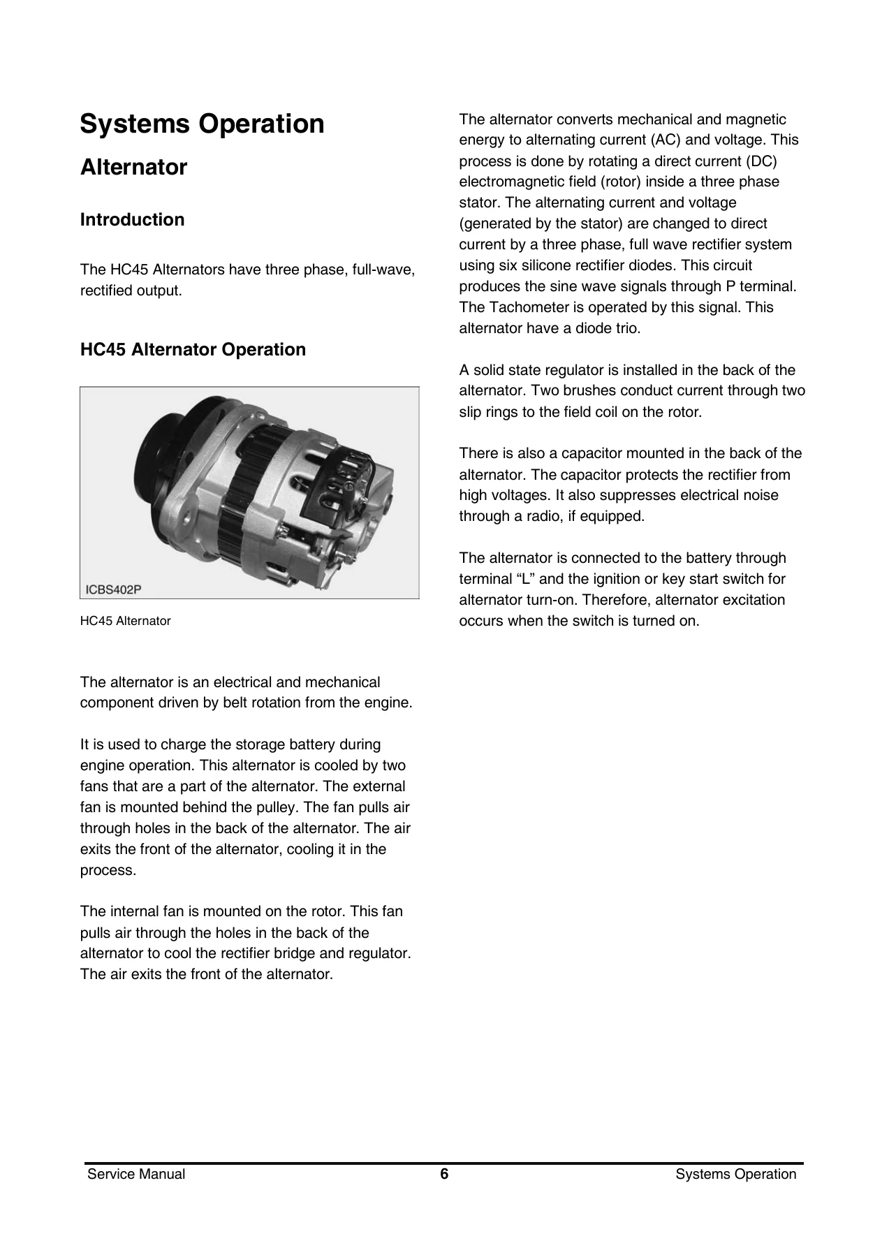
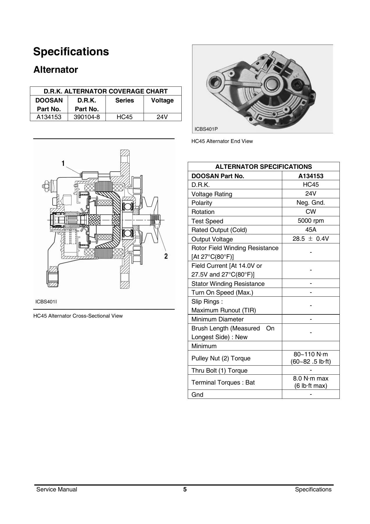
- Engine – Alternator – HC45 alternator operation, components, output test, machine test
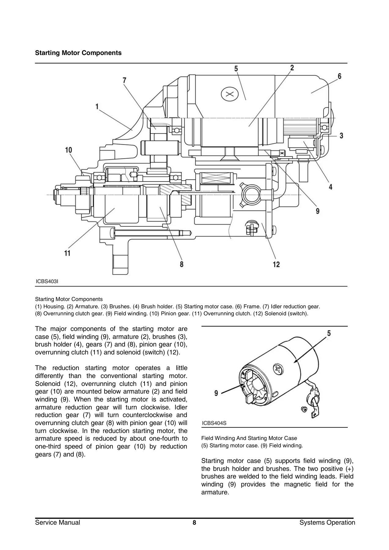
- Engine – Starting Motor – Poong Sung reduction starting motor R4.5, operation, troubleshooting, component testing, disassembly and assembly
- Engine – G643(E) LP Engine – general information, recommended maintenance, engine mechanical system, engine electrical system, engine management system, LPG fuel delivery system, basic troubleshooting, advanced diagnostics
- Engine – DB58S Diesel Engine (Tier II) – engine specifications, technical information, maintenance, disassembly, inspection, reassembly, commissioning and operation, lubrication system, cooling system, fuel system, injection pump calibration, special tool list
- Engine – D439E Diesel Engine (Tier III) – general information, engine mechanical system, engine electrical system, fuel system, engine control system, ECU, fuel delivery system, service tool G-scan
- Engine – V3800 Diesel Engine (Tier IV Interim) – specifications, wiring diagrams, general precautions, maintenance check list, DPF system, common rail system, service tool Diagmaster, troubleshooting, diagnostic procedures by DTC
- Power Train – Two Speed Transmission – specifications, system operation, testing and adjusting, disassembly and assembly, drive axle
- Power Train – Three Speed Power Shift Transmission (3WG 116/161) – systems operation, fault codes, electronic controls, AEB calibration, disassembly and assembly
- Power Train – Three Speed Power Shift Transmission (3WG94) – description, operation, maintenance, disassembly and assembly
- Vehicle System – hydraulic specification, systems operation, testing and adjusting, brake system, steering system, disassembly and assembly, hydraulic schematic, electric schematic
- Mast System – carriage, rollers, mast, specifications, systems operation, testing and adjusting, chain adjustment, drift test
- Operation & Maintenance Manual – safety section, general section, operation section, maintenance section, index section
What makes this Doosan D50S-5 D90S-5 G50S-5 G70S-5 service manual particularly useful is its structure as a compilation of the individual service publications that Doosan Infracore produced for each major system. Rather than forcing you to track down separate manuals for the engine, transmission, hydraulic system and mast, this single PDF gathers all of the relevant form numbers into one complete resource. Each section retains the full depth of the original standalone publication, so nothing is lost in the compilation. The engine coverage alone spans four completely different powerplants: the DB58S Tier II diesel, the D439E Tier III diesel, the V3800 Tier IV Interim diesel with common rail and DPF, and the G643(E) LP engine with its closed-loop fuel management system. This makes the manual applicable across a wide range of D50S-5 through D90S-5 and G50S-5 through G70S-5 forklift configurations.
For technicians working on the diesel-powered D-series trucks, the DB58S section covers the 5.8-litre six-cylinder engine in extensive detail, including performance curves, engine assembly views, diagnosis and remedy tables, valve clearance adjustment, injection timing, cylinder head bolt tightening, injection pump calibration data and a full special tool list. The D439E Tier III section adds coverage of the 3.9-litre four-cylinder common rail engine with its electronic control unit, pin connector diagrams, circuit diagrams and sensor inspection procedures. The V3800 Tier IV Interim section goes further with the diesel particulate filter system, DPF regeneration and cleaning procedures, common rail system component descriptions, diagnostic tool connection, active test procedures and an extensive DTC list with detailed diagnostic procedures for every fault code. This means that whether you are dealing with an older Tier II truck or a newer Tier IV Interim machine, the manual has the specific diagnostic and repair information you need.
The LP engine coverage in the G643(E) section is equally thorough, spanning the engine management system overview, LPG fuel system operation, electronic throttle system, SECM wiring diagrams, sensor inspection and repair, mixer and regulator service, idle mixture adjustment and advanced diagnostics with fault code reading and clearing procedures. For LP-powered G-series trucks, this section provides the specialised knowledge required to safely and correctly service the fuel delivery and electronic control systems.
On the power train side, the manual covers both the two-speed transmission and the three-speed power shift transmissions in the 3WG 116/161 and 3WG94 variants. The two-speed section includes converter stall tests, transmission pressure tests, inching pedal adjustment, wheel brake adjustment and complete disassembly and assembly procedures for the transmission and drive axle. The three-speed sections provide system operation explanations, hydraulic schematics, clutch application charts, electronic control unit information, fault code definitions and the AEB (automatic calibration of shifting elements) procedure. This level of transmission coverage is essential for diagnosing shift quality issues, performing clutch calibrations and carrying out major internal repairs.
The Vehicle System section addresses the hydraulic system, brake system and steering system. It includes the hydraulic control valve configuration, lift and tilt spool operation, brake power master cylinder operation, steering unit oil flow, relief valve pressure checks, steering system pressure checks, brake system deaeration and steering axle stop adjustment. The mast system section covers carriage and roller service, mast adjustment, chain wear testing, chain adjustment, tilt angle checks and drift testing for both the lift and tilt systems. Together these sections give you the information needed to keep the entire vehicle operating safely and correctly, not just the engine and transmission.
The Operation & Maintenance Manual portion included in this compilation adds another layer of value. It covers the operator’s station and monitoring systems, seat switch system, lift truck controls, refueling procedures, starting procedures, operating techniques, parking, storage, transportation, towing, fork inspection, tire inflation, torque specifications, cooling system specifications, fuel specifications, lubricant specifications and the complete maintenance intervals schedule. This means the manual serves both as a workshop reference and as a guide for daily operation and preventive maintenance.
Why This Manual Matters
Having the correct service information is critical when working on any piece of industrial equipment. The Doosan D50S-5 D90S-5 G50S-5 G70S-5 service manual provides the exact torque values, clearances, pressure settings and adjustment procedures that Doosan specifies for these trucks. Using incorrect specifications can lead to premature component failure, unsafe operating conditions or costly damage. With this manual, you can be confident that every repair, from a simple oil change to a complete engine overhaul, is performed to the manufacturer’s standards.
The diagnostic procedures in the engine and transmission sections are particularly valuable. The V3800 Tier IV Interim diesel section includes detailed diagnostic procedures for every DTC, with step-by-step instructions for checking sensors, wiring harnesses and actuators. The three-speed transmission sections include fault code lists with probable causes and corrective actions. The G643(E) LP section includes a full troubleshooting guide with preliminary checks, visual and physical checks, basic inspection procedures and connector inspection procedures. This diagnostic depth means you can systematically identify and resolve problems rather than relying on guesswork or parts swapping.
The manual also includes extensive wiring diagrams, hydraulic schematics and component illustrations. These visual references are invaluable when tracing circuits, identifying connectors, understanding hydraulic flow paths or identifying the location of specific components on the machine. The electric schematic section covers various model configurations including cabin and non-cabin versions, different engine and transmission combinations, and different emission tiers, ensuring that you have the correct diagram for the specific truck you are working on.
Delivery and Usage
IMAGES PREVIEW
This Doosan D50S-5 D90S-5 G50S-5 G70S-5 forklift service manual is delivered as an instant PDF download immediately after payment. There is no shipping, no waiting and no physical media to worry about. The PDF format means you can access the manual on any device – laptop, desktop, tablet or smartphone – whether you are in the workshop, at the machine or on the road. You can print individual pages or sections as needed, making it easy to have the relevant procedure or specification right next to you while you work. The complete manual is contained in a single PDF file, so you do not have to manage multiple documents or search through several files to find the information you need.
For anyone who owns, operates or maintains Doosan D50S-5 through D90S-5 or G50S-5 through G70S-5 forklifts, this service manual is an essential investment. It gives you the ability to perform repairs and maintenance correctly the first time, reducing downtime, extending equipment life and ensuring safe operation. Whether you are a professional technician, a fleet maintenance manager or an owner-operator who prefers to handle your own servicing, this manual provides the technical depth and breadth required to get the job done right.
Reviews
There are no reviews yet.