★ TRUSTED BY 321,897+ PROFESSIONALS WORLDWIDE
🏢
Trusted Business
Verified & Licensed
🛡️
Virus Free Files
100% Safe Downloads
🔒
Secure Payment
SSL Protected
Instant Delivery
Available Immediately
Sale!

Doosan DX300LCA Excavator Shop Manual 5001 and Up – April 2018 PDF

Original price was: $44.95.Current price is: $27.95.

Comprehensive Doosan DX300LCA Excavator Shop Manual for Serial Number 5001 and Up. Publication 950106-00075BE, April 2018, with detailed repair procedures, component removal and installation, hydraulic testing and troubleshooting, electrical information, specifications, torque data, optional attachment systems, and hydraulic/electrical schematics.

SKU: HD-DX300LCA-950106-00075BE-2018 Category: Tags: , , , Vendor: ServiceDeskPDFs
Instant PDF Download
Available immediately
💾
Save to Your Device
Download & keep forever
🛡️
Antivirus Scanned
100% virus-free
🌍
Trusted Worldwide
175,000+ customers

Description

Doosan DX300LCA Excavator Shop Manual 5001 and Up – April 2018 PDF

This Doosan DX300LCA Excavator Shop Manual 5001 and Up – April 2018 PDF is a detailed technical service reference for the DX300LCA excavator, covering machines from Serial Number 5001 and Up. The manual is organized around the machine’s major structures and working systems, with procedures for inspection, testing, adjustment, component removal, installation, disassembly, reassembly and troubleshooting. Publication number 950106-00075BE is dated April 2018 and extends across 1,056 PDF pages.

The manual goes well beyond basic maintenance. It provides dimensional and performance data, standard torque information, component construction drawings, hydraulic circuits, electrical information, troubleshooting paths and step-by-step workshop procedures. Major assemblies such as the main pump, control valves, swing and travel devices, front attachment, hydraulic cylinders and undercarriage components are treated individually, making the manual useful when a repair requires access deeper than routine servicing.

File Details

  • Manual type: Shop Manual
  • Brand: DOOSAN
  • Model: DX300LCA Excavator
  • Serial coverage: 5001 and Up
  • Document number: 950106-00075BE
  • Publication date: April 2018
  • Edition: Edition 1
  • Language: English
  • Pages: 1,056
  • File format: PDF

Specifications, Performance Checks and Workshop Data

The specifications portion gives a useful baseline before diagnosis or component work begins. It identifies machine component locations and provides general dimensions, working-range information, weights, capacities and operational performance standards. For the standard configuration shown in the manual, shipping weight is listed as 29.2 metric tons (64,375 lb), including 10% fuel, boom, 3,100 mm (10′ 2″) arm, 1,334 mm (4′ 5″) backhoe bucket and standard shoes. Fuel tank capacity is listed as 500 L (132.1 U.S. gal), hydraulic system capacity as 280 L (74 U.S. gal), and hydraulic reservoir capacity as 160 L (42 U.S. gal).

Performance testing is treated as a diagnostic procedure rather than simply a specification list. The manual explains test preparation and evaluation, then provides standards for engine speed, hydraulic pressure, front attachment cycle speed, swing performance, cylinder creeping and travel performance. Procedures include hydraulic cylinder cycle-time measurement, 20 m travel-speed testing, raised-track revolution testing, mistrack checking, swing-speed measurement and swing-function drift checking. These procedures allow measured machine behavior to be compared with the standards printed in the manual before parts are adjusted or replaced.

The general maintenance and standard torque sections support the repair chapters with guidance on welding, hydraulic cleanliness, leakage prevention, cleaning, inspection and bearing diagnosis. Torque references cover standard metric and U.S. fasteners, Type 8 phosphate-coated hardware, hose clamps, ORFS swivel nuts and hydraulic split flanges, along with guidance for torque-wrench extension tools and tightening applications.

Detailed Component Repair Coverage

The DX300LCA shop manual separates major components into individual service sections. The cabin chapter, for example, covers cabin removal and installation, glass dimensions and procedures for removing and installing cabin glass. The counterweight chapter includes safe lifting and removal procedures as well as reinstallation information. Separate hydraulic oil tank and fuel tank chapters provide specifications, component illustrations, removal and installation sequences, connection information and completing-work procedures.

Hydraulic component coverage becomes increasingly detailed through the upper-structure chapters. The main pump section includes axial piston pump specifications, performance curves, port identification, hydraulic circuit information, parts illustrations, sectional views, operating theory, tightening torque, removal, installation, disassembly, reassembly and troubleshooting. Separate chapters address the drive coupling, main control valve, swing device, rotation gear pump, joystick valve, travel control valve with damper, solenoid valve, EPPR valve and accumulator.

The lower structure and chassis are also serviced as individual assemblies. Swing bearing, center joint, travel device and track assembly coverage supports work on the rotating connection, travel system and crawler components. The front attachment section addresses the boom and arm, bucket and cylinders. Procedures include front attachment removal and installation, bucket tooth inspection and replacement, bucket O-ring and shimming work, and related component service where covered by the individual chapters.

Complete PDF Bookmark Tree

Complete Bookmarks

The complete bookmarks in the “Doosan DX300LCA Excavator Shop Manual 5001 and Up – April 2018 PDF” are as follows:

DX300LCAp. 1
Table of Contentsp. 3
Safetyp. 5
Track Excavator Maintenance Safetyp. 7
Safety Instructionsp. 11
Safety Messagesp. 11
Generalp. 12
Safe Operation is Operator's Responsibilityp. 12
Know Your Machinep. 12
Proper Work Tools and Attachmentsp. 13
Pressurized Fluidsp. 13
Flying or Falling Objectsp. 14
Personal Protective Equipment (PPE)p. 15
Correction of Machine Problemsp. 15
Crushing and Cuttingp. 15
Hot Coolant and Oils – Burn Preventionp. 16
Fire and Explosion Preventionp. 17
Fire Extinguisher and First-aid Kit (Emergency Medical Kit)p. 20
Electrical System and Electrical Shockp. 21
Transportationp. 23
Obey State and Local Over-the-Road Regulationsp. 23
Loading and Unloadingp. 23
Transporting Machinep. 24
Operationp. 25
Before Engine Startingp. 25
Work Sitep. 26
Mounting/Dismountingp. 27
Cleaningp. 28
Operator Stationp. 28
Seat Beltp. 29
Visibility Informationp. 30
Boost Starting or Charging Engine Batteriesp. 31
Starting Enginep. 32
Swinging or Travelingp. 33
Lifting and Diggingp. 35
Operation on Slopesp. 36
Towingp. 37
Attachmentp. 38
Equipment Lowering with Engine Stoppedp. 38
Engine Stopp. 39
Parking Machinep. 39
Preservation/Storing Machinep. 40
Maintenancep. 42
Warning Tagp. 45
Cleaningp. 46
Proper Tools and Clothingp. 46
Disassembling Precautionsp. 46
Use of Lightingp. 46
Fire and Explosion Preventionp. 47
Burn Preventionp. 48
Rubber That Contains Fluoridesp. 49
Rubber and Plasticsp. 50
Welding Repairsp. 51
Warning for Counterweight and Front Attachment Removalp. 52
Lock Inspection Coversp. 53
Working on Machinep. 53
Accumulatorp. 54
Compressed Airp. 54
Track Tension Adjustmentsp. 55
Supports and Blocking for Work Equipmentp. 55
High-pressure Lines, Tubes and Hosesp. 56
Batteryp. 57
Environment and Circumstancesp. 59
Work Site Areas Requiring Extra Cautionp. 59
High-voltage Cablesp. 61
Underground Operationp. 62
Working in Waterp. 62
Working in Contaminated Environmentp. 62
Operation in Extreme Conditionsp. 63
Exhaust Ventilationp. 67
Asbestos Informationp. 68
Silica Dust Informationp. 68
Disposal of Hazardous Materialsp. 69
Soundp. 70
Vibrationp. 70
Specificationsp. 71
Specificationsp. 73
Safety Instructionsp. 77
General Descriptionp. 77
Component Locationsp. 78
General Dimensionsp. 80
Working Rangep. 82
General Specificationsp. 84
Performance Testsp. 86
Purpose of Performance Testsp. 86
Kinds of Testsp. 86
Performance Standardsp. 86
Precautions for Evaluation of Test Datap. 86
Definition of "Performance Standard"p. 86
Preparation for Performance Testsp. 87
The Machinep. 87
Test Areap. 87
Precautionsp. 87
Make Precise Measurementp. 87
Operational Performance Standard Tablep. 88
Operational Performance Testp. 90
Hydraulic Cylinder Cycle Timep. 90
Travel Speedp. 92
Track Revolution Speedp. 93
Mistrack Checkp. 95
Swing Speedp. 97
Swing Function Drift Checkp. 98
General Maintenancep. 99
General Maintenance Instructionsp. 101
Safety Instructionsp. 105
Welding Precautions and Instructionsp. 106
Hydraulic System – General Precautionsp. 107
Maintenance Service and Repair Procedurep. 109
General Precautionsp. 109
Hydraulic System Cleanliness and Oil Leaksp. 110
Maintenance Precautions for Hydraulic System Servicep. 110
Oil Leakage Precautionsp. 111
Cleaning and Inspectionp. 112
General Instructionsp. 112
Bearing Inspectionp. 113
Standard Torquesp. 121
Safety Instructionsp. 125
Torque Values for Standard Metric Fastenersp. 126
Torque Values for Standard U.S. Fastenersp. 127
Type 8 Phosphate Coated Hardwarep. 129
Torque Values for Hose Clampsp. 130
ORFS Swivel Nut Recommended Torquep. 130
Torque Values for Split Flangesp. 131
Torque Wrench Extension Toolsp. 132
Torque Multiplicationp. 132
Other Uses for Torque Wrench Extension Toolsp. 133
Tightening Torque Specifications (Metric)p. 134
Upper Structurep. 137
Cabinp. 139
Safety Instructionsp. 143
Removalp. 144
Installationp. 148
Dimensions of Cabin Glassp. 151
Removal and Installation of Cabin Glassp. 155
Removal of Cabin Glassp. 155
Installation of Cabin Glassp. 157
Installation of Upper Door Glassp. 162
Installation of Upper Front Glassp. 162
Counterweightp. 163
Safety Instructionsp. 167
Generalp. 168
Warning for Counterweight and Front Attachment Removalp. 168
Removalp. 170
Installationp. 171
Hydraulic Oil Tankp. 173
Safety Instructionsp. 177
Generalp. 177
Specificationp. 177
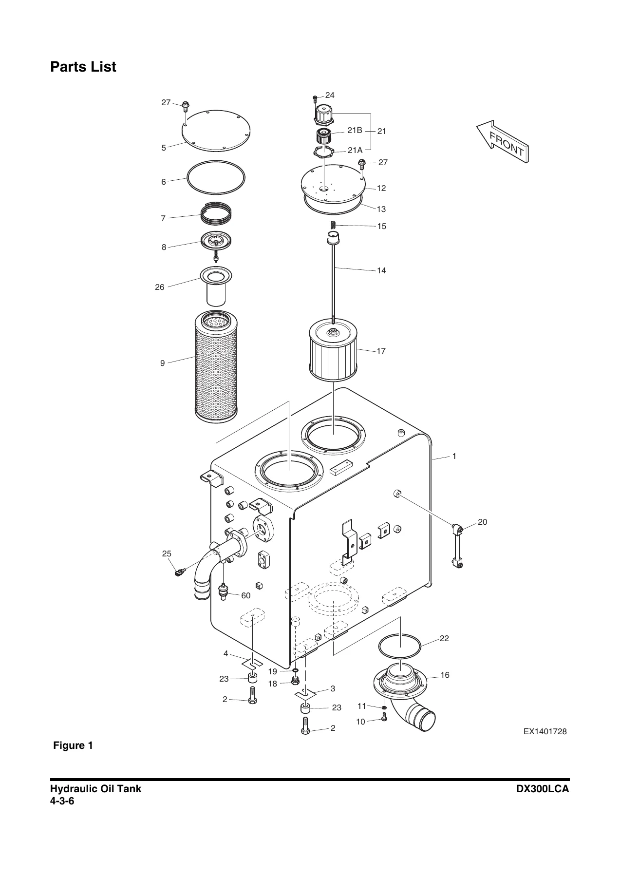
Parts Listp. 178
Air Breatherp. 180
Removalp. 181
Installationp. 187
Completing Workp. 188
Fuel Tankp. 189
Safety Instructionsp. 193
Generalp. 193
Specificationp. 193
Parts Listp. 194
Removalp. 196
Installationp. 201
Completing Workp. 202
Main Pumpp. 203
Safety Instructionsp. 207
Axial Piston Pumpp. 207
Specificationsp. 207
Overviewp. 209
Hydraulic Circuitp. 211
Parts Listp. 212
Section Viewp. 214
Theory of Operationp. 216
Toolsp. 218
Tightening Torquep. 219
Removalp. 220
Installationp. 229
Completing Workp. 229
Disassemblyp. 230
Reassemblyp. 233
Troubleshootingp. 236
Maintenance Instructionsp. 238
Regulatorp. 240
Parts Listp. 240
Port and Hydraulic Circuitp. 242
Functional Explanationp. 243
Adjustmentp. 250
Tightening Torquep. 253
Toolsp. 253
Section Viewp. 254
Disassemblyp. 256
Reassemblyp. 259
Troubleshootingp. 262
Pilot Gear Pumpp. 263
Specificationp. 263
Parts Listp. 264
Theory of Operationp. 265
Port and Hydraulic Circuitp. 265
Precautionp. 266
Drive Coupling (Main Pump)p. 267
Safety Instructionsp. 271
Generalp. 271
Descriptionp. 271
Specificationp. 271
Parts Listp. 272
Section Viewp. 274
Toolsp. 275
Disassemblyp. 276
Reassemblyp. 277
Main Control Valvep. 279
Safety Instructionsp. 283
Generalp. 283
Specificationp. 283
Overviewp. 284
Parts Listp. 290
Theory of Operationp. 296
Cautions for Operationp. 324
Precautionp. 325
Tools and Torquesp. 325
Removalp. 326
Installationp. 335
Completing Workp. 336
Disassemblyp. 337
Caution on Disassemblyp. 337
Sequence of Disassemblyp. 338
Cleaning and Inspectionp. 349
Cleaningp. 349
Inspectionp. 349
Reassemblyp. 350
Caution on Assemblyp. 350
Sequence of Subassemblyp. 351
Maintenance of Relief Valvesp. 362
Troubleshooting, Testing and Adjustmentp. 365
Troubleshootingp. 365
Adjustment of Valvesp. 367
Swing Devicep. 371
Safety Instructionsp. 375
Generalp. 375
Specificationp. 375
Overviewp. 376
Parts Listp. 378
Theory of Operationp. 382
Removalp. 385
Installationp. 389
Completing workp. 389
Section Viewp. 390
Swing Motorp. 390
Swing Reduction Gearp. 392
Precautionp. 394
Tools and Tightening Torquep. 394
Disassemblyp. 395
General Cautionsp. 395
Swing Motorp. 395
Swing Reduction Gearp. 403
Reassemblyp. 412
General Cautionsp. 412
Swing Motorp. 412
Swing Reduction Gearp. 426
Troubleshootingp. 452
General Precautionsp. 452
How to Check Faults of Hydraulic Motorp. 452
Troubleshootingp. 453
Maintenance Instructionsp. 454
Replacement Standard of Worn Partsp. 454
Standard of Sliding Surface Correctionp. 454
Gear Pump (Rotation)p. 455
Safety Instructionsp. 459
Generalp. 459
Specificationp. 459
Overviewp. 460
Parts Listp. 461
Single Gear Pumpp. 462
Disassemblyp. 462
Reassemblyp. 464
Joystick Valve (Work Lever)p. 469
Safety Instructionsp. 473
Generalp. 473
Specificationsp. 473
Overviewp. 474
Parts Listp. 476
Theory of Operationp. 478
Section Viewp. 480
Removalp. 482
Installationp. 487
Completing workp. 488
Tools and Torquesp. 489
Disassemblyp. 489
Reassemblyp. 493
Travel Control Valve (with Damper)p. 501
Safety Instructionsp. 505
Generalp. 506
Specificationp. 506
Overviewp. 507
Parts Listp. 508
Theory of Operationp. 510
Tools and Torquesp. 511
Section Viewp. 512
Removalp. 513
Installationp. 518
Completing Workp. 519
Disassemblyp. 520
Reassemblyp. 523
Troubleshootingp. 528
Solenoid Valvep. 529
Safety Instructionsp. 533
Generalp. 533
Specificationp. 533
Overviewp. 534
Parts Listp. 536
Theory of Operationp. 537
Functions of Solenoid Valvep. 538
EPPR Valvep. 541
Safety Instructionsp. 545
Generalp. 545
Specificationp. 545
Overviewp. 547
Hydraulic Circuitp. 548
Troubleshootingp. 548
Accumulatorp. 549
Safety Instructionsp. 553
Generalp. 553
Specificationsp. 555
Lower Structure and Chassisp. 557
Swing Bearingp. 559
Safety Instructionsp. 563
Generalp. 564
General Descriptionp. 564
Parts Listp. 564
Maintenance Guidelinesp. 565
Disassemblyp. 566
Reassemblyp. 568
Center Jointp. 569
Safety Instructionsp. 573
Generalp. 573
General Descriptionp. 573
Overviewp. 574
Parts Listp. 575
Section Viewp. 576
Removalp. 577
Installationp. 581
Completing Workp. 581
Disassemblyp. 582
Reassemblyp. 585
Troubleshooting, Testing and Adjustmentp. 587
Inspectionp. 587
Testingp. 587
Travel Devicep. 589
Safety Instructionsp. 593
Generalp. 593
Specificationp. 593
Overviewp. 594
Parts Listp. 596
Theory of Operationp. 600
Cautions for Operationp. 608
Precautionp. 612
Tools for Disassembly and Assemblyp. 612
Tightening Torquep. 614
Removalp. 615
Installationp. 620
Completing Workp. 621
Section Viewp. 622
Disassemblyp. 626
General Caution Mattersp. 626
Reduction Gearp. 626
Hydraulic Motorp. 632
Cleaning and Inspectionp. 637
Maintenance Standardp. 637
Reassemblyp. 639
General Caution Mattersp. 639
Hydraulic Motorp. 639
Reduction Gearp. 647
Checkup After Assemblyp. 655
Performance Testp. 655
Troubleshootingp. 657
Track Assemblyp. 661
Safety Instructionsp. 665
Generalp. 665
Track Tensionp. 666
Track Shoes and Linksp. 668
Parts Listp. 668
Track Removalp. 669
Track Installationp. 671
Wear Limits and Tolerancesp. 672
Sprocketp. 674
Wear Limits and Tolerancesp. 674
Front Idlerp. 675
Parts Listp. 675
Front Idler Disassemblyp. 676
Front Idler Reassemblyp. 678
Wear Limits and Tolerancesp. 679
Upper Rollerp. 680
Parts Listp. 680
Upper Roller Removalp. 681
Upper Roller Installationp. 681
Upper Roller Disassemblyp. 682
Upper Roller Reassemblyp. 683
Wear Limits and Tolerancesp. 684
Lower Rollerp. 685
Parts Listp. 685
Lower Roller Removalp. 686
Lower Roller Installationp. 686
Lower Roller Disassemblyp. 686
Lower Roller Reassemblyp. 687
Wear Limits and Tolerancesp. 689
Track Adjusterp. 690
Parts Listp. 690
Disassemblyp. 691
Assemblyp. 692
Frontp. 695
Boom and Armp. 697
Safety Instructionsp. 701
Specificationsp. 702
One – Piece Boomp. 702
Two – Piece Boomp. 704
Removalp. 706
Arm Removalp. 706
Boom Removalp. 708
Installationp. 709
Arm Installationp. 709
Boom Installationp. 709
Completing Workp. 710
Bucketp. 711
Safety Instructionsp. 715
Bucket Tooth Inspection and Replacementp. 716
Bucket O-ring Replacementp. 717
Bucket Shimming Proceduresp. 718
New Bucket Installationp. 718
Shimming Procedures for Installed Bucketp. 719
Bucket Replacement and Reversalp. 720
Replacementp. 721
Reversalp. 722
Cylindersp. 723
Safety Instructionsp. 727
Generalp. 727
General Descriptionp. 727
Specificationp. 727
Parts Listp. 728
Theory of Operationp. 736
Seal of Cylinderp. 737
Special Tools and Materialsp. 739
Piston Nutp. 739
Piston Jigp. 740
Steel Bushing Jigp. 741
Dust Wiper Jigp. 742
Slipper Seal Jigp. 743
Slipper Seal Straightening Jigp. 744
Rod Bushing (DD-bushing) Pushing-in Jigp. 745
Disassemblyp. 746
Reassemblyp. 751
Troubleshootingp. 755
Hydraulic Systemp. 757
Hydraulic Systemp. 759
Safety Instructionsp. 763
Hydraulic Systemp. 763
General Descriptionp. 763
Hydraulic Schematicp. 764
General Descriptionp. 764
Hydraulic Component and Oil Flowp. 766
Hydraulic Componentsp. 766
Main Oil Linep. 768
Pilot Oil Linep. 769
Return Oil Linep. 770
Safety Cutoff Valve Operationp. 771
Power Up Valve Operationp. 772
Travel High-speed Valve Operationp. 774
Swing Brake Release Operationp. 776
Travel Forward and Backward Operationp. 778
Boom Up Operationp. 780
Boom Down Operationp. 782
Arm Dump Operationp. 784
Arm Crowd Operationp. 786
Bucket Dump Operationp. 788
Bucket Crowd Operationp. 790
Combined Bucket Crowd and Boom Up Operationp. 792
Combined Travel and Boom, Arm, Bucket or Swing Operationp. 794
Two Pump Operationp. 796
Hydraulic System Testing and Adjustmentp. 797
Safety Instructionsp. 801
Procedural Troubleshooting Baseline Recommendationsp. 801
Initial Checks and Tests to Establish Operating Condition of the Excavatorp. 801
Pilot Pressurep. 803
Adjustment and Testingp. 803
Power Mode Valvep. 804
Current Signal and Hydraulic Pressure Adjustmentsp. 804
Pressure Up Valvep. 805
Checks and Adjustmentsp. 805
Pump Input Power Controlp. 807
Pump Regulator Adjustmentp. 807
Flow Meter and Flow Meter Kit Installation and Testingp. 810
Swing System Troubleshootingp. 812
Precautions/Initial Checksp. 812
Swing Relief Valve Checking and Adjustmentp. 813
Hydraulic System Troubleshootingp. 815
Safety Instructionsp. 819
Hydraulic Systemp. 819
Unusual Noise Comes Out from Pump Connectionp. 819
Engine Starts but Machine Does Not Operatep. 820
Hydraulic Oil is Cloudyp. 821
Hydraulic Oil Overheatedp. 821
Hydraulic Pump Cavitationp. 822
Hydraulic Oil is Contaminatedp. 822
Boom, Arm, Bucket Speed is Slowp. 823
Boom, Arm or Bucket Power is Weakp. 824
Cylinder Moves When Remote Control Valve is in the Neutral Positionp. 824
TR (L), TR (R) Swing Does Not Operate When Remote Control Valve Operatedp. 825
Swing Speed is Slowp. 826
Machine Swings but Does Not Stopp. 827
One Side Speed is Falls and the Machine Curvesp. 828
Machine Does Not Stop on a Slopep. 829
Travel Motor is Powerless (Travel Only)p. 829
Machine Makes a Curved Travel, When Travel and Actuator Operation are Executed a the Same Timep. 830
Does Not Travel is 2nd Speed or Auto Speedp. 830
Troubleshooting – Swing Gearboxp. 831
Troubleshooting – Hydraulic Problemsp. 832
Troubleshooting – Control Valvep. 834
Troubleshooting – Travel Control Valvep. 835
Troubleshooting – Joystick Control Valvep. 836
Electrical Systemp. 837
Electrical Systemp. 839
Safety Instructionsp. 845
Introductionp. 845
Electrical Supply Systemp. 846
Engine Starting Circuitp. 848
Start Operationp. 848
After Startp. 850
Engine Preheating Systemp. 852
Engine Stopp. 854
Charging Systemp. 856
Monitoring Systemp. 857
Instrument Panelp. 858
Monitoring System Schematicp. 860
Operationp. 862
Instrumentsp. 862
Warning and Indicator Lightsp. 864
Indication of Warning Lightsp. 864
Indication of Multifunction Gaugep. 865
Initial Operationp. 867
Mode Selector Switchp. 867
Graphic Information Area Displayp. 868
Overviewp. 868
Main Menus for the Graphic Display Areap. 869
Menu Selector Buttonsp. 869
Main Menup. 870
Languagep. 870
Set Clockp. 871
Filter/Oil Infop. 871
Adjust Displayp. 872
Set Passwordp. 873
Special Menup. 874
Entering/Accessing and Exiting/Escaping Menusp. 874
Special Menu Selectionsp. 875
Electronic Hydraulic Control System (EPOS)p. 892
Control System Schematicp. 892
Power Mode Controlp. 894
Operationp. 896
Power Mode Control – Circuit Diagramp. 899
Engine Control Systemp. 900
Engine Control Motorp. 901
Engine Control Dialp. 902
Engine Control Circuit Diagramp. 903
Automatic Deceleration Control (Auto Idle Control)p. 904
Engine Overheat Protection Systemp. 906
Power Boost Modep. 908
Operationp. 908
Power Boost Control – Circuit Diagramp. 909
Automatic Travel Speed Controlp. 910
Automatic Travel Speed Control – Circuit Diagramp. 912
Self-diagnostic Functionp. 913
EPOS Controllerp. 913
Air Conditioner Systemp. 915
Outlinep. 915
Internal and External Filtersp. 916
Air-Conditioning System Layoutp. 918
Air Conditioner/Heater Circuit Diagramp. 919
Air Conditioner/Heater Unitp. 920
Ambient Air Temperature Sensorp. 925
Sun Sensorp. 926
Control Panelp. 926
Compressorp. 934
Receiver Dryerp. 934
Troubleshootingp. 935
Refrigerant System Repairsp. 937
Refrigerant Safe Handling Proceduresp. 937
Repair and Replacement Procedurep. 938
Refrigerant Recoveryp. 940
Vacuuming Refrigerant Systemp. 940
Leakage Checkp. 942
Refrigerant Chargingp. 942
Inspecting System For Leakagep. 944
Wiper Systemp. 945
Wiper Circuitp. 945
Wiper operationp. 946
Lighting Systemp. 948
Lighting System Circuit Diagramp. 948
Kind of Lightp. 949
Operationp. 949
Overload Warning Devicep. 950
Overload Warning Device Circuit Diagramp. 950
Audio Controllerp. 951
Audio Controller Circuit Diagramp. 951
Optionsp. 953
One Wayp. 955
Safety Instructionsp. 959
Generalp. 959
General Descriptionp. 959
Theory of Operationp. 959
Hydraulic Circuitp. 960
Caution for Installationp. 961
Installation Procedurep. 962
Main Piping – One Wayp. 962
Pilot Piping – One and Two-wayp. 964
Pilot Piping – One Wayp. 966
Boom Piping – One and Two-wayp. 968
Arm Piping – One and Two-wayp. 970
After Installation Precautionsp. 971
Air Bleedingp. 971
Completing Workp. 972
Two-wayp. 973
Safety Instructionsp. 977
Generalp. 977
General Descriptionp. 977
Theory of Operationp. 977
Structurep. 978
Hydraulic Circuitp. 979
Caution for Installationp. 981
Installation Procedurep. 982
Main Piping – Two-wayp. 982
Pilot Piping – One and Two-wayp. 984
Pilot Piping – Two-wayp. 986
Pilot Piping – Two-way (Pedal)p. 988
Floor Mat – Two-wayp. 990
Boom Piping – One and Two-wayp. 992
Arm Piping – One and Two-wayp. 994
After Installation Precautionsp. 995
Air Bleedingp. 995
Completing Workp. 996
Rotatingp. 997
Safety Instructionsp. 1001
Generalp. 1001
General Descriptionp. 1001
Theory of Operationp. 1001
Structurep. 1002
Hydraulic Circuitp. 1003
Caution for Installationp. 1004
Installation Procedurep. 1006
Main Piping – Rotatingp. 1006
Pilot Piping – Rotating (1)p. 1008
Pilot Piping – Rotating (2)p. 1010
Floor Mat – Rotatingp. 1012
Boom Piping – Rotatingp. 1014
Arm Piping – Rotatingp. 1016
After Installation Precautionsp. 1017
Air Bleedingp. 1017
Completing Workp. 1017
Quick Couplerp. 1019
Safety Instructionsp. 1023
Generalp. 1023
General Descriptionp. 1023
Theory of Operationp. 1023
Hydraulic Circuitp. 1024
Caution for Installationp. 1024
Quick Coupler Operationp. 1025
Securing Work Toolp. 1025
Attaching Quick Coupler to Excavatorp. 1026
Releasing the Work Toolp. 1027
Installation Procedurep. 1028
Main Piping – Quick Couplerp. 1028
Pilot Piping – Quick Couplerp. 1030
Electric Parts – Quick Couplerp. 1031
Boom Piping – Quick Couplerp. 1032
Arm Piping – Quick Couplerp. 1034
After Installation Precautionsp. 1035
Air Bleedingp. 1035
Completing Workp. 1035
Two Pumpp. 1037
Safety Instructionsp. 1041
Generalp. 1041
General Descriptionp. 1041
Theory of Operationp. 1041
Hydraulic Circuitp. 1042
Caution for Installationp. 1043
Installation Procedurep. 1044
Main Piping – Two Pumpp. 1044
Pilot Piping – Two Pumpp. 1046
Switch – Two Pumpp. 1048
After Installation Precautionsp. 1049
Air Bleedingp. 1049
Schematicp. 1051
Hydraulic Schematic / Electrical Schematicp. 1053

Hydraulic Testing and Troubleshooting

A substantial part of the Doosan DX300LCA Excavator Shop Manual 5001 and Up – April 2018 PDF is devoted to understanding and diagnosing the hydraulic system. The system description identifies the main pump, pilot components, accumulator, joystick and pedal valves, main control valve, cylinders, swing device, travel devices, center joint, filters, tank and optional hydraulic equipment. Operating explanations describe how pump output and control-valve circuits are distributed to travel, swing, boom, arm, bucket and optional functions.

The testing and adjustment material includes hydraulic pressure and pump-output checks and provides test conditions so readings can be compared with the manual’s performance data. The troubleshooting section follows real machine symptoms, including abnormal pump-connection noise, a machine that starts but does not operate, cloudy or overheated hydraulic oil, swing faults, travel faults and control-valve or joystick-related problems. Separate troubleshooting material addresses the swing gearbox, hydraulic problems, control valve, travel control valve and joystick control valve. This structure helps narrow a fault through checks rather than relying only on component replacement.

Electrical and Optional Equipment Information

The electrical section includes system descriptions, instrument and monitoring information, sensors, switches, relays, controllers and associated circuit material. The manual identifies items such as the instrument panel, starter switch, front and rear pump pressure sensors, hydraulic oil temperature sensor, fuel sensor, filter switches, alternator, EPOS controller, battery, battery relay, circuit breaker, fuse box, coolant temperature sensor, engine speed sensor and engine oil pressure switch. Electrical schematic material is included at the end of the manual alongside the hydraulic schematic.

Optional hydraulic arrangements are not left out. Dedicated chapters cover One Way, Two-way, Rotating, Quick Coupler and Two Pump systems. These sections include applicable component and piping information, installation-related procedures and operating connections where shown. This is particularly useful when a DX300LCA is equipped with auxiliary hydraulic functions rather than only the standard digging arrangement.

Chapters Covered

  • 1 Safety
    • Track Excavator Maintenance Safety
  • 2 Specifications
    • Specifications
  • 3 General Maintenance
    • General Maintenance Instructions
    • Standard Torques
  • 4 Upper Structure
    • Cabin
    • Counterweight
    • Hydraulic Oil Tank
    • Fuel Tank
    • Main Pump
    • Drive Coupling (Main Pump)
    • Main Control Valve
    • Swing Device
    • Gear Pump (Rotation)
    • Joystick Valve (Work Lever)
    • Travel Control Valve (with Damper)
    • Solenoid Valve
    • EPPR Valve
    • Accumulator

    IMAGES PREVIEW

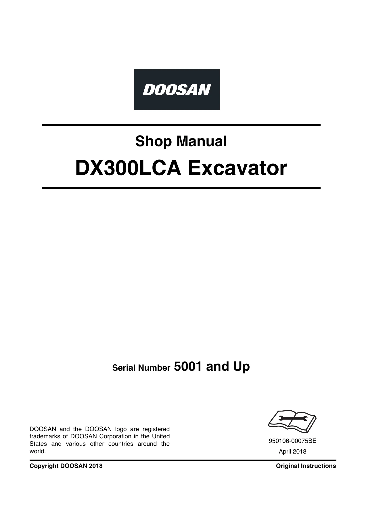
    Doosan DX300LCA Excavator Shop Manual 5001 and Up - April 2018 PDF — PDF page 1 preview
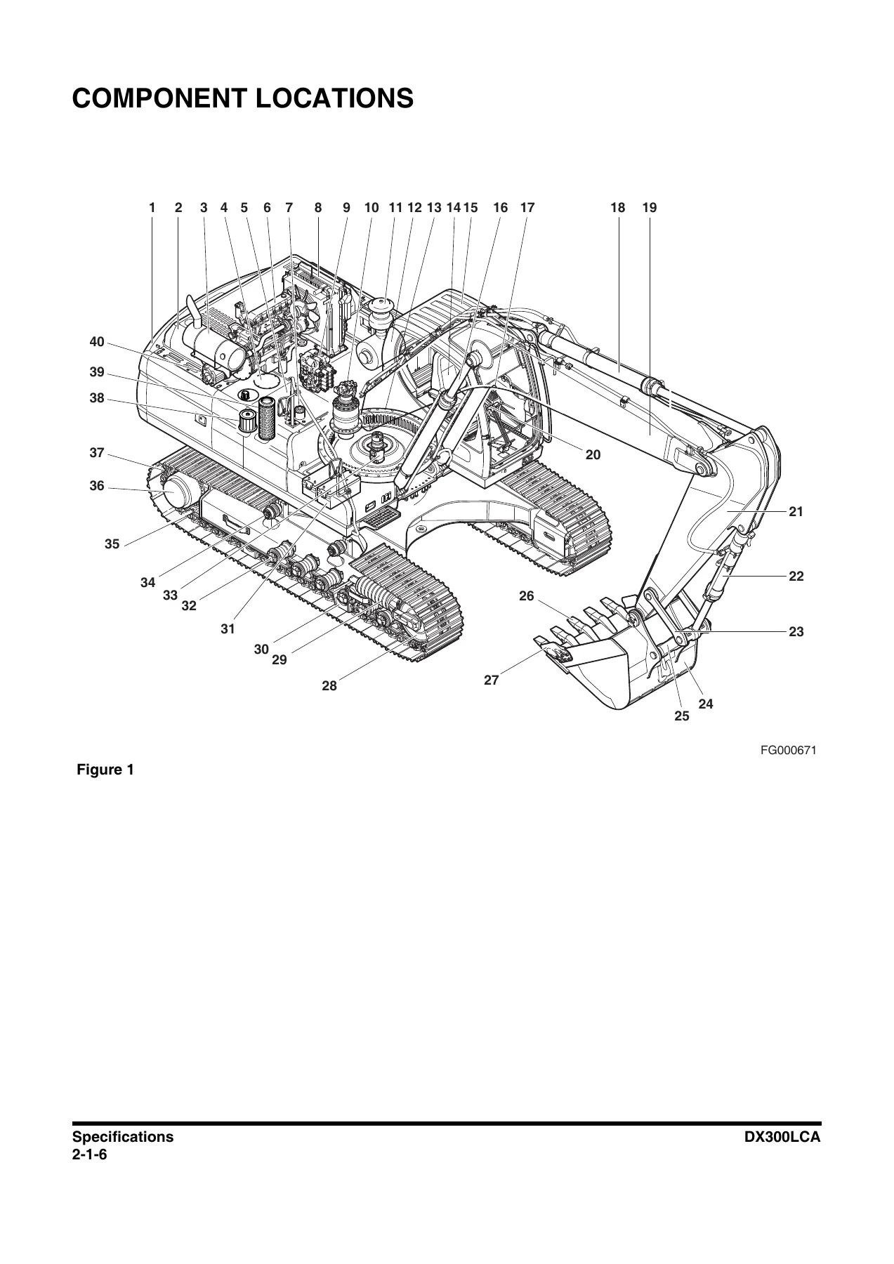
    Doosan DX300LCA Excavator Shop Manual 5001 and Up - April 2018 PDF — PDF page 78 preview
    Doosan DX300LCA Excavator Shop Manual 5001 and Up - April 2018 PDF — PDF page 178 preview

  • 5 Lower Structure and Chassis
    • Swing Bearing
    • Center Joint
    • Travel Device
    • Track Assembly
  • 6 Front
    • Boom and Arm
    • Bucket
    • Cylinders
  • 7 Hydraulic System
    • Hydraulic System
    • Hydraulic System Testing and Adjustment
    • Hydraulic System Troubleshooting
  • 8 Electrical System
    • Electrical System
  • 9 Options
    • One Way
    • Two-way
    • Rotating
    • Quick Coupler
    • Two Pump
  • 10 Schematic
    • Hydraulic Schematic/Electrical Schematic

Taken together, these chapters provide a workshop reference that follows the DX300LCA from machine-level specifications and performance evaluation down to individual assemblies and circuits. A technician can use the same manual to identify a component, review system operation, check expected performance, follow removal or disassembly instructions, inspect parts, apply specified tightening data and use troubleshooting information to investigate operating faults.

Repair and Diagnose Your DX300LCA with the Correct Reference

The Doosan DX300LCA Excavator Shop Manual 5001 and Up – April 2018 PDF supports substantial workshop work on the excavator: hydraulic diagnosis and adjustment, pump and valve service, swing and travel repairs, undercarriage work, front attachment service, cylinder work, cabin and tank removal, electrical-system reference and schematic tracing. Having the procedures, specifications, torque values, test standards and component illustrations together is especially valuable when a repair involves several connected systems or when measured performance needs to be checked against the manual before disassembly.

After purchase, the manual is supplied as an instant PDF download. There is no physical book and no shipping delay. You can open the PDF on a computer, tablet or compatible mobile device and print the pages or sections you need for workshop use.
Reviews

There are no reviews yet.

Be the first to review “Doosan DX300LCA Excavator Shop Manual 5001 and Up – April 2018 PDF”

What Our Customers Say

★★★★★ Live reviews from customers
Loading customer reviews...
0
    0
    Your Cart
    Your cart is emptyReturn to Shop
    🛒
    Recently Purchased
    🕒 verified order