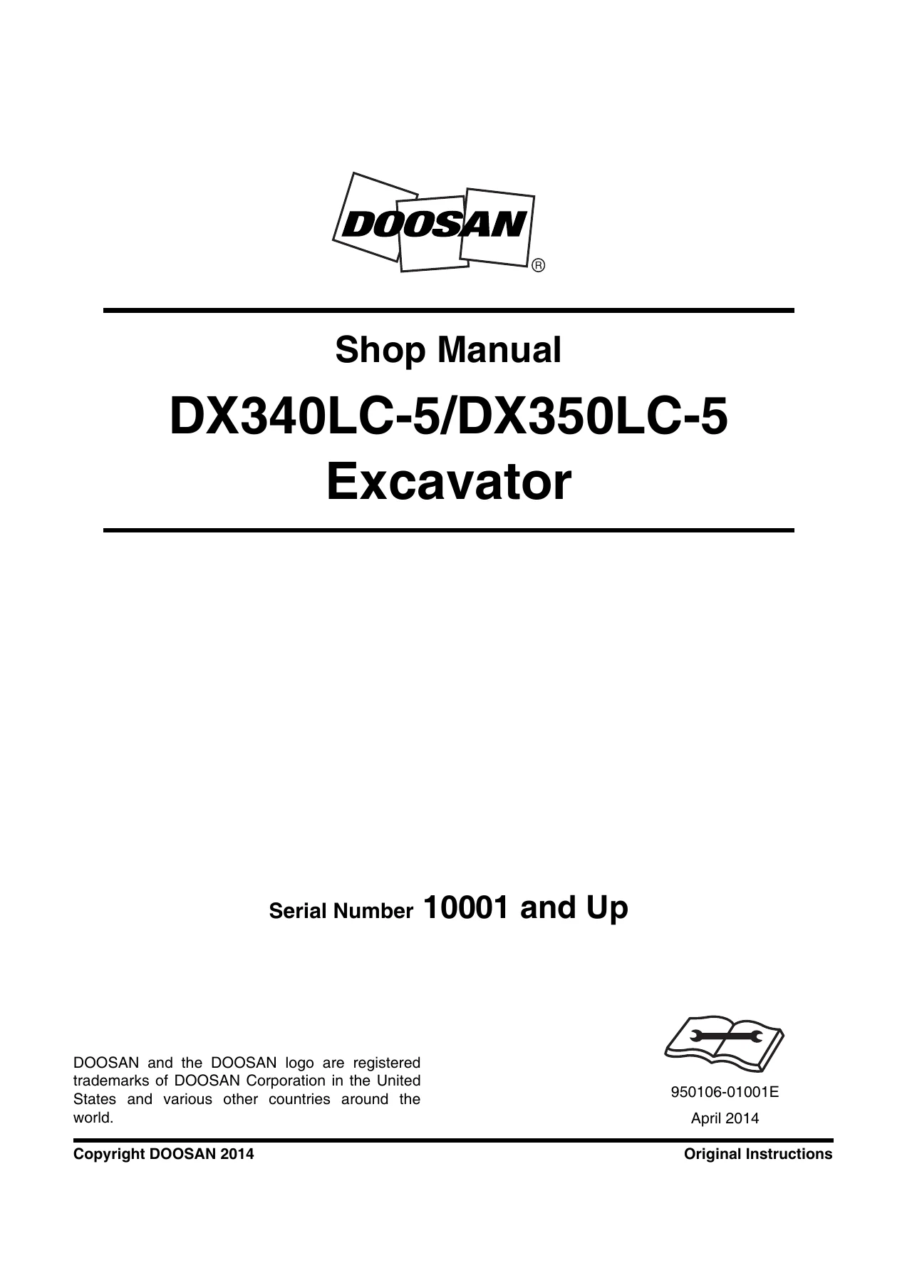
Doosan DX340LC-5 DX350LC-5 Excavator Shop Manual 950106-01001E – April 2014
$49.95 Original price was: $49.95.$29.95Current price is: $29.95.
Complete 1,631-page shop manual for Doosan DX340LC-5 and DX350LC-5 excavators, Serial Number 10001 and Up. Covers specifications, DC 9 engine service, upper and lower structures, boom and arm, bucket, cylinders, hydraulic testing and troubleshooting, electrical systems, attachment options, torque data, and hydraulic/electrical schematics.
Description
Doosan DX340LC-5 DX350LC-5 Excavator Shop Manual 950106-01001E – April 2014
This Doosan DX340LC-5 DX350LC-5 Excavator Shop Manual 950106-01001E – April 2014 provides detailed service and repair information for DX340LC-5 and DX350LC-5 excavators with Serial Number 10001 and Up. Across 1,631 pages, it brings together machine specifications, performance standards, component service procedures, hydraulic and electrical information, engine repair data, adjustment procedures, troubleshooting, torque specifications, attachment systems, and schematics.
The manual is organized around the excavator’s major assemblies, allowing a technician to move from machine-level specifications and testing into individual components such as the main pump, control valve, swing device, travel device, front attachment, cylinders, and electrical and hydraulic circuits. Removal, installation, disassembly, reassembly, inspection, testing, and troubleshooting information is included throughout the relevant sections.
File Details
- Manual type: Shop Manual
- Brand: DOOSAN
- Models: DX340LC-5 / DX350LC-5
- Serial coverage: 10001 and Up
- Document number: 950106-01001E
- Edition: 1st Edition
- Date: April 2014
- Language: English
- Page count: 1,631 pages
- File format: PDF
Machine Specifications and Performance Information
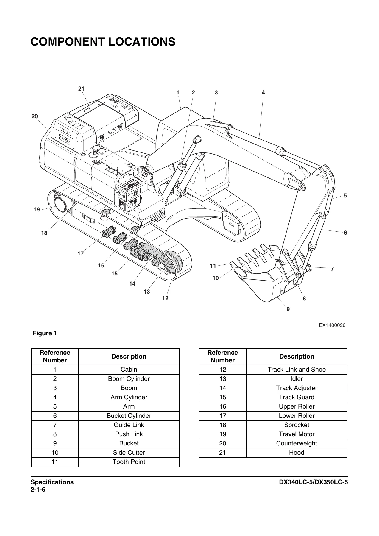
The specifications section of the Doosan DX340LC-5 DX350LC-5 shop manual identifies component locations and provides general dimensions for both one-piece and two-piece boom configurations. Working-range information covers different arm and bucket combinations, while general specifications include machine weights, digging forces, tank and hydraulic capacities, bucket capacity ranges, shoe choices, and ground-pressure data.
Performance testing receives its own detailed coverage. The manual explains test preparation, test-area requirements, measurement practices, and performance standards before moving into procedures for hydraulic cylinder cycle times, travel speed, track revolution speed, mistrack, swing speed, and swing drift. This gives technicians defined methods for comparing actual machine operation with the standards printed in the manual instead of relying only on subjective symptoms.
Examples of machine data included in the manual include a shipping weight of 34.9 tons (76,941 lb), a 600 liter (158.5 U.S. gal) fuel tank, 450 liter (118.8 U.S. gal) hydraulic system capacity, and 240 liter (63.4 U.S. gal) hydraulic reservoir capacity. The bucket heaped capacity range is listed as 1.25 – 2.01 m3 (1.63 – 2.63 yd3), with additional dimensional and working-range data provided for the available front configurations.
IMAGES PREVIEW
DC 9 Engine Service and Repair Coverage
A substantial engine section covers the DC 9 engine fitted to the machines in this manual. Engine specification data identifies a 5-cylinder, straight, 4-cycle water-cooled engine with air-to-air intercooling and direct injection. Rated net power is listed as 237 kW (318 HP) at 1,800 rpm, displacement as 9,300 cc, bore as 130 mm, stroke as 140 mm, and compression ratio as 17:1. The engine section also contains identification information, performance curves, special tools, tightening torques, inspection procedures, and extensive component-level repair instructions.
Coverage extends through the cylinder head, valve mechanism, cylinder block and liner, camshaft, connecting rod, crankshaft, flywheel, piston, roller tappet, timing gear, lubrication system, exhaust and aftertreatment components, cooling system, fuel system, and engine electrical controls. Fuel-system subjects include the accumulator, fuel manifold, overflow valve, feed pump, injectors, filter and heater, together with troubleshooting. Exhaust-system coverage includes the variable geometry turbocharger, oxidation catalytic converter, EGR system, reductant components and related sensors. The manual also provides numerous component-specific tightening procedures and torque values for engine assembly work.
Hydraulic Service, Testing and Troubleshooting
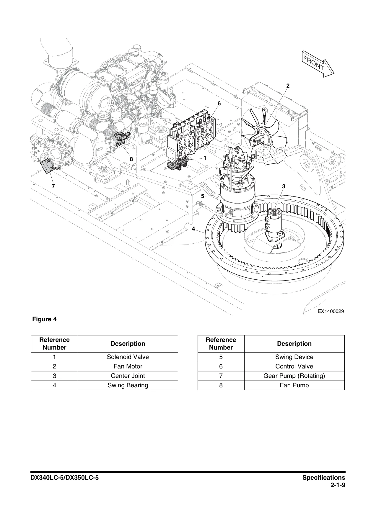
Hydraulic information is spread through both component chapters and dedicated hydraulic-system sections. The manual covers the main pump, main control valve, swing device, fan pump and fan motor, joystick and travel control valves, solenoid valve, accumulator, center joint, travel device, cylinders, hydraulic tank and related circuitry. General hydraulic maintenance guidance emphasizes system cleanliness, contamination prevention, oil-leak inspection, correct assembly practices and pressure-release precautions.
The dedicated hydraulic chapters explain system operation and include testing, adjustment and troubleshooting information. The hydraulic system identifies major components such as the two main pumps, control valve, swing and travel devices, boom, arm and bucket cylinders, pilot components, valves, filters, oil cooler, hydraulic tank, attachment-control valves and associated circuits. This makes the manual useful both when tracing a hydraulic function and when servicing the individual hardware responsible for that function.
Component Removal, Overhaul and Installation
The Doosan DX340LC-5 DX350LC-5 Excavator Shop Manual contains component-focused sections for the upper structure, undercarriage and front attachment. Depending on the assembly, these sections include specifications, parts identification, theory of operation, inspection, removal, installation, disassembly, reassembly, maintenance standards and troubleshooting. The swing device section, for example, covers the swing motor, reduction gear, parking brake, hydraulic circuit, removal and installation, complete disassembly and reassembly, troubleshooting and worn-part standards.
The lower structure covers the swing bearing, center joint, travel device and track assembly. Front equipment coverage includes the boom and arm, bucket and hydraulic cylinders. Procedures are supported by component illustrations, connection information, tightening values and service precautions where applicable.
Torque and Assembly Reference
General maintenance material includes welding precautions, hydraulic-system precautions, cleaning and inspection methods, bearing inspection and repair practices. A dedicated standard-torque section contains metric and U.S. fastener torque charts, Type 8 phosphate-coated hardware values, hose-clamp values, ORFS swivel nut recommendations, split-flange torque values and information on torque-wrench extension tools. Separate engine pages provide normal and special tightening torques as well as component-specific sequences for assemblies such as the cylinder head, connecting rods, flywheel, fuel system and other engine parts.
Chapters Covered
- 1. Safety
- Track Excavator Maintenance Safety: safety messages, general precautions, transportation, operation, maintenance, environment and circumstances
- 2. Specifications
- Component locations, general dimensions, one-piece and two-piece boom configurations, working ranges, general specifications, workload material weights, performance standards and operational performance tests
Complete PDF Bookmark TreeComplete Bookmarks
The complete bookmarks in the “Doosan DX340LC-5 DX350LC-5 Excavator Shop Manual 950106-01001E – April 2014” are as follows:
+DX340LC-5/DX350LC-5p. 1
NOTICEp. 3Table of Contentsp. 5+Safetyp. 7
+Track Excavator Maintenance Safetyp. 9
Safety Instructionsp. 13Safety Messagesp. 13+Generalp. 14
Safe Operation is Operator's Responsibilityp. 14Know Your Machinep. 14Proper Work Tools and Attachmentsp. 15Pressurized Fluidsp. 15Flying or Falling Objectsp. 16Personal Protective Equipment (PPE)p. 17Correction of Machine Problemsp. 17Crushing and Cuttingp. 17Hot Coolant and Oils – Burn Preventionp. 18Fire and Explosion Preventionp. 19Fire Extinguisher and First-aid Kit (Emergency Medical Kit)p. 22Electrical System and Electrical Shockp. 23Roll-over Protective Structure (ROPS)p. 23+Transportationp. 27
Obey State and Local Over-the-Road Regulationsp. 27Loading and Unloadingp. 27Transporting Machinep. 28+Operationp. 29
Before Engine Startingp. 29Work Sitep. 30Mounting/Dismountingp. 31Cleaningp. 32Operator Stationp. 32Seat Beltp. 33Visibility Informationp. 34Boost Starting or Charging Engine Batteriesp. 35Starting Enginep. 36Swinging or Travelingp. 37Lifting and Diggingp. 39Operation on Slopesp. 40Towingp. 41Attachmentp. 42Equipment Lowering with Engine Stoppedp. 42Engine Stopp. 43Parking Machinep. 43Preservation/Storing Machinep. 44+Maintenancep. 46
Warning Tagp. 49Cleaningp. 50Proper Tools and Clothingp. 50Disassembling Precautionsp. 50Use of Lightingp. 50Fire and Explosion Preventionp. 51Burn Preventionp. 52Rubber That Contains Fluoridesp. 53Rubber and Plasticsp. 54Welding Repairsp. 55Warning for Counterweight and Front Attachment Removalp. 56Lock Inspection Coversp. 57Working on Machinep. 57Accumulatorp. 58Compressed Airp. 58Track Tension Adjustmentsp. 59Supports and Blocking for Work Equipmentp. 59High-pressure Lines, Tubes and Hosesp. 60Batteryp. 61+Environment and Circumstancesp. 63
Work Site Areas Requiring Extra Cautionp. 63High-voltage Cablesp. 65Underground Operationp. 66Working in Waterp. 66Working in Contaminated Environmentp. 66Operation in Extreme Conditionsp. 67Exhaust Ventilationp. 71Asbestos Informationp. 72Silica Dust Informationp. 72Disposal of Hazardous Materialsp. 73Soundp. 74Vibrationp. 74+Specificationsp. 75
+Specificationsp. 77
Safety Instructionsp. 81General Descriptionp. 81Component Locationsp. 82+General Dimensionsp. 86
One – Piece Boomp. 86Two – Piece Boomp. 87+Working Rangep. 88
One – Piece Boomp. 88Two – Piece Boomp. 90General Specificationsp. 92Approximate Weight of Workload Materialsp. 94+Performance Testsp. 96
Purpose of Performance Testsp. 96Kinds of Testsp. 96Performance Standardsp. 96Precautions for Evaluation of Test Datap. 96Definition of "Performance Standard"p. 97+Preparation for Performance Testsp. 97
The Machinep. 97Test Areap. 97Precautionsp. 97Make Precise Measurementp. 98Operational Performance Standard Tablep. 99+Operational Performance Testp. 101
Hydraulic Cylinder Cycle Timep. 101Travel Speedp. 103Track Revolution Speedp. 104Mistrack Checkp. 106Swing Speedp. 108Swing Function Drift Checkp. 109+General Maintenancep. 111
+General Maintenance Instructionsp. 113
Safety Instructionsp. 117Welding Precautions and Instructionsp. 118Hydraulic System – General Precautionsp. 119+Maintenance Service and Repair Procedurep. 121
General Precautionsp. 121+Hydraulic System Cleanliness and Oil Leaksp. 122
Maintenance Precautions for Hydraulic System Servicep. 122Oil Leakage Precautionsp. 123+Cleaning and Inspectionp. 124
General Instructionsp. 124Bearing Inspectionp. 125+Standard Torquesp. 133
Safety Instructionsp. 137Torque Values for Standard Metric Fastenersp. 138Torque Values for Standard U.S. Fastenersp. 139Type 8 Phosphate Coated Hardwarep. 141Torque Values for Hose Clampsp. 142ORFS Swivel Nut Recommended Torquep. 142Torque Values for Split Flangesp. 143+Torque Wrench Extension Toolsp. 144
Torque Multiplicationp. 144Other Uses for Torque Wrench Extension Toolsp. 145Tightening Torque Specifications (Metric)p. 146+Enginep. 149
+Enginep. 151
Safety Instructionsp. 157Overviewp. 158+Inspectionp. 159
Cleaning the Enginep. 159+Special Toolsp. 159
Mounting the Engine in a Universal Standp. 169+Engine Identificationp. 170
Engine Data Platep. 170Engine Specificationp. 171Engine Performance Curvesp. 172+Tightening Torquesp. 174
Normal Tightening Torquep. 174Special Tightening Torquep. 178+Cylinderp. 206
Cylinder Headp. 206Valve Mechanismp. 224Cylinder Blockp. 227Cylinder Linerp. 242Flywheel Housingp. 249Front Coverp. 252Oil Mist Separatorp. 254+Actuating Systemp. 260
Camshaftp. 260Connecting Rodp. 268Crankshaftp. 270Flywheelp. 279Pistonp. 284Roller Tappetp. 290Intake Manifoldp. 291Power Take Offp. 291Torsion Damperp. 292Belt Circuitp. 293Balance Shaft Unitp. 300Timing Gearp. 305+Lubrication Systemp. 311
General Informationp. 311Centrifugal Oil Cleanerp. 313Oil Coolerp. 318Oil Filterp. 321Oil Pumpp. 322Oil Sumpp. 324Oil Pressure Sensorp. 325Troubleshooting Chips Found in the Enginep. 326Troubleshooting the Lubrication Systemp. 330Lubrication Oil Consumptionp. 331+Exhaust Systemp. 334
General Informationp. 334T113, Exhaust Temperature Sensor before Catalytic Converterp. 350T115, NOx Sensorp. 351T131 NOx Sensorp. 352T116, Reductant Pick-up Unitp. 354Evaporatorp. 359V117 Reductant Doserp. 359V118, Coolant Valve for Heating the Reductant Systemp. 366V183 Reductant Pumpp. 368H25, H26 Electrically Heated Reductant Hosep. 379M4000 Electric Exhaust Brakep. 380Reductant Tankp. 386Oxidation Catalytic Converterp. 393Exhaust Manifoldp. 395Variable Geometry Turbochargerp. 403EGR Systemp. 411EGR Valvep. 418EGR Coolerp. 423+Cooling Systemp. 425
Internal Cleaning of Cooling Systemp. 428Charge Air Coolerp. 429Charge Air Temperature Sensorp. 431Charge Air Pressure Sensorp. 433Coupling Coil for AC Compressorp. 434Thermostatp. 435Coolant Pumpp. 438Coolant Temperature Sensorp. 439+Fuel Systemp. 441
General Informationp. 441Accumulatorp. 446Fuel Manifoldp. 447Overflow Valvep. 456Feed Pumpp. 459Injectorp. 465Fuel Filterp. 471Fuel Heaterp. 475Fuel System Troubleshootingp. 476+Electrical Systemp. 490
E44, Control Unit EMSp. 490Control Unit EECp. 506Engine Speed Sensorp. 511T110 Oil Level Sensorp. 513T111, Fuel Pressure Sensorp. 514T125, Exhaust Back Pressure Sensorp. 516T135, Camshaft Position Sensorp. 517V109, Solenoid Valve for Charge Pressurep. 519V120, Fuel Inlet Metering Valvep. 520V142, V143, V144, V145, V146 Solenoid Valve for Injectorp. 522T8, Coolant Level Monitorp. 523P3, Alternatorp. 524M1, Starter Motorp. 534AC Compressorp. 537Electrical Partsp. 540EMS S8 (1/2)p. 551EMS S8 (2/2)p. 553EEC, EEC3 Exhaust Emission Control (9, 13 Liter Engines XPI)p. 555+Engine Coolant Heater (Option)p. 557
Safety Instructionsp. 561+Disassembly and Assemblyp. 561
Changing the Circulating Pumpp. 561Changing the Temperature Limiterp. 563Changing the Temperature Sensorp. 564Changing the Combustion Air Fanp. 566Changing the Burner, Flame Monitor and Glow Plugp. 568Changing the Burner Headp. 570Changing the Heat Exchangerp. 572+Upper Structurep. 573
+Cabinp. 575
Safety Instructionsp. 579+Cabin Identificationp. 579
Roll-over Protective Structure (ROPS)p. 579Removalp. 581Installationp. 585Dimensions of Cabin Glassp. 588+Removal and Installation of Cabin Glassp. 592
Removal of Cabin Glassp. 592Installation of Cabin Glassp. 594Installation of Upper Door Glassp. 599Installation of Upper Front Glassp. 599+Counterweightp. 601
Safety Instructionsp. 605+Generalp. 606
Warning for Counterweight and Front Attachment Removalp. 606Removalp. 608Installationp. 609+Hydraulic Oil Tankp. 611
Safety Instructionsp. 615+Generalp. 615
Specificationp. 615Parts Listp. 616Air Breatherp. 618Removalp. 619Installationp. 624Completing Workp. 625+Fuel Tankp. 627
Safety Instructionsp. 631+Generalp. 631
Specificationp. 631Parts Listp. 632Removalp. 634Installationp. 638Completing Workp. 639+Main Pumpp. 641
Safety Instructionsp. 647+Generalp. 647
Specificationsp. 647Overviewp. 650Hydraulic Circuitp. 651Parts Listp. 652Theory of Operationp. 656Manual Overridep. 664Angle Sensorp. 666+PPRV (Peak Pressure Reducing Valve)p. 667
Installationp. 674Hydraulic Oilp. 674Guide for External Oil Leakagep. 674+Repairp. 675
Necessary Tools and Jigsp. 675Cautions During Disassembling and Assemblingp. 676Disassembling Procedurep. 677Assembling Procedurep. 680+Precautionp. 681
Tightening Torquesp. 681Slotted Screwsp. 681Threaded Plugsp. 682Sealing Nutsp. 683+Maintenance and Repairp. 684
Cleaning and Carep. 684Inspectionp. 685Maintenancep. 685Repairp. 686Spare Partsp. 686Decommissioningp. 687+Removal and Replacementp. 687
Required Toolsp. 687Preparing for Removalp. 687Removing the Axial Piston Unitp. 688Preparing the Components for Storage or Further Usep. 688+Troubleshootingp. 689
How to Proceed for Troubleshootingp. 689Malfunction Tablep. 690Section Viewp. 692Removalp. 693Installationp. 702Completing Workp. 702+Replacing Seals and Assembly Groupsp. 703
Replacing the Shaft Sealp. 704Sealing or Replacing the Gear Pumpp. 707Sealing the Cover of the Power Take-offp. 709Sealing the Port Plate with Valvep. 711Sealing or Replacing the Pressure Reducing Valvep. 713Replacing the Angle Position Sensorp. 715Replacing Sealing Nutsp. 717+D-Eco Power Systemp. 718
Introduction of D-Eco Power Systemp. 718Initialization of D-Eco Power Systemp. 728+D-Eco Power Diagnostic Tools Operationp. 754
Program Startp. 754D-Eco Power Diagnostic Tools Main Screenp. 755Contents and Functionp. 755D-Eco Power Diagnostic Check Listp. 756+D-Eco Power Diagnostic Tools Checkp. 757
Joystick Checkp. 757Angle Checkp. 770EPPR V/V Checkp. 774Main Pump Checkp. 780Relief Pressure Checkp. 786+Drive Coupling (Main Pump)p. 791
Safety Instructionsp. 795+Generalp. 795
Specificationp. 795Parts Listp. 796+Section Viewp. 798
Toolsp. 799Disassemblyp. 800Reassemblyp. 800+Main Control Valvep. 803
Safety Instructionsp. 807+Generalp. 807
Specificationp. 807Overviewp. 808Parts Listp. 812Theory of Operationp. 815Removalp. 856Installationp. 864Completing Workp. 864+Disassemblyp. 865
General Repair Instructionsp. 865Repair Instructionsp. 866+Reassemblyp. 885
Maintenance and Repairp. 892+Troubleshootingp. 898
Troubleshooting, Testing and Adjustmentp. 898+Start-up Proceduresp. 901
Commissioningp. 901+Swing Devicep. 905
Safety Instructionsp. 909+Generalp. 909
Specificationp. 909Overviewp. 910Hydraulics Circuitp. 911Parts Listp. 912Theory of Operationp. 917Cautions for Operationp. 925+Precautionp. 929
Tools for Disassembly and Assemblyp. 929Removalp. 931Installationp. 935Completing workp. 935Disassembly and Reassemblyp. 936+Troubleshootingp. 957
General Instructionsp. 957Examination of Hydraulic Motorp. 957Troubleshootingp. 958+Maintenance Instructionsp. 961
Replacement Standard of Worn Partsp. 961Standard of Sliding Surface Correctionp. 961+Fan Pump for Oil Coolerp. 963
Safety Instructionsp. 967+Generalp. 968
Specificationp. 968Overviewp. 969Parts Listp. 970Theory of Operationp. 972+Maintenance Guidelinesp. 977
Sealing Driveshaftp. 978Sealing Control Valvep. 980Toolsp. 980Removalp. 981Installationp. 984Completing Workp. 985+Section Viewp. 986
EPPR Valvep. 986+Disassemblyp. 987
Disassembly of Rotary Groupp. 988Disassembly of Control Devicep. 989Disassembly of Shaft/Bearingsp. 990Cleaning and Inspectionp. 991+Reassemblyp. 994
Adjustment of Taper Roller Bearingp. 995+Fan Motor for Oil Coolerp. 1001
Safety Instructionsp. 1005+Generalp. 1005
Specificationp. 1005Overviewp. 1006Parts List and Section Viewp. 1007+Precautionp. 1008
Toolsp. 1008Removalp. 1009Installationp. 1013Completing Workp. 1013Disassemblyp. 1014+Reassemblyp. 1017
Reassemblyp. 1017Assemblyp. 1018+Gear Pump (Rotation)p. 1021
Safety Instructionsp. 1025+Generalp. 1025
Specificationp. 1025Overviewp. 1026Parts Listp. 1027+Joystick Valve (Work Lever)p. 1029
Safety Instructionsp. 1033+Generalp. 1033
Specificationsp. 1033Overviewp. 1034Parts Listp. 1036Theory of Operationp. 1038Tools and Torquesp. 1039Section Viewp. 1040Removalp. 1042Installationp. 1047Completing workp. 1047Disassemblyp. 1048Reassemblyp. 1052+Travel Control Valve (with Damper)p. 1059
Safety Instructionsp. 1063+Generalp. 1064
Specificationp. 1064Overviewp. 1065Parts Listp. 1066Theory of Operationp. 1068Tools and Torquesp. 1069Section Viewp. 1070Removalp. 1071Installationp. 1074Completing Workp. 1077Disassemblyp. 1078Reassemblyp. 1081Troubleshootingp. 1086+Solenoid Valvep. 1087
Safety Instructionsp. 1091+Generalp. 1091
Specificationp. 1091Overviewp. 1092Parts Listp. 1094Theory of Operationp. 1095Disassembly and Reassemblyp. 1096Troubleshootingp. 1097+Accumulatorp. 1099
Safety Instructionsp. 1103+Generalp. 1103
Specificationsp. 1105+Two Pumpp. 1107
Safety Instructionsp. 1111+Generalp. 1111
Theory of Operationp. 1111Hydraulic Circuitp. 1112Layoutp. 1113+Lower Structure and Chassisp. 1115
+Swing Bearingp. 1117
Safety Instructionsp. 1121+Generalp. 1122
General Descriptionp. 1122Parts Listp. 1122Maintenance Guidelinesp. 1123Disassemblyp. 1124Reassemblyp. 1126+Center Jointp. 1127
Safety Instructionsp. 1131+Generalp. 1131
General Descriptionp. 1131Overviewp. 1132Parts Listp. 1133Section Viewp. 1134Disassemblyp. 1135Reassemblyp. 1138+Troubleshooting, Testing and Adjustmentp. 1140
Inspectionp. 1140Testingp. 1140+Travel Devicep. 1141
Safety Instructionsp. 1145+Generalp. 1145
Specificationp. 1145Overviewp. 1146Parts Listp. 1148Theory of Operationp. 1152Cautions for Operationp. 1162+Precautionp. 1166
Tools for Disassembly and Assemblyp. 1166Tightening Torquep. 1168Removalp. 1169Installationp. 1174Completing Workp. 1175Section Viewp. 1176+Disassemblyp. 1178
Cautions on Disassemblyp. 1178Disassembly Sequencep. 1178+Reassemblyp. 1188
Cautions on Assemblyp. 1188Assembly Sequencep. 1188Performance Testp. 1205Troubleshootingp. 1207+Track Assemblyp. 1209
Safety Instructionsp. 1213Generalp. 1213Track Tensionp. 1214+Track Shoes and Linksp. 1216
Parts Listp. 1216Track Removalp. 1217Track Installationp. 1219Wear Limits and Tolerancesp. 1220+Sprocketp. 1222
Wear Limits and Tolerancesp. 1222+Front Idlerp. 1223
Overviewp. 1223Parts Listp. 1224Front Idler Disassemblyp. 1225Front Idler Reassemblyp. 1227+Upper Rollerp. 1228
Overviewp. 1228Parts Listp. 1229Upper Roller Removalp. 1230Upper Roller Installationp. 1230Upper Roller Disassemblyp. 1230Upper Roller Reassemblyp. 1232+Lower Rollerp. 1233
Overviewp. 1233Parts Listp. 1234Lower Roller Removalp. 1235Lower Roller Installationp. 1235Lower Roller Disassemblyp. 1235Lower Roller Reassemblyp. 1236+Track Adjusterp. 1238
Parts Listp. 1238Disassemblyp. 1239Assemblyp. 1240+Frontp. 1243
+Boom and Armp. 1245
Safety Instructionsp. 1249+Specificationsp. 1250
One – Piece Boomp. 1250Two – Piece Boomp. 1252+Removalp. 1254
Arm Removalp. 1254Boom Removalp. 1256+Installationp. 1257
Arm Installationp. 1257Boom Installationp. 1257Completing Workp. 1258+Bucketp. 1259
Safety Instructionsp. 1263Bucket Tooth Inspection and Replacementp. 1264Bucket O-ring Replacementp. 1265+Bucket Shimming Proceduresp. 1266
+New Bucket Installationp. 1266
Shimming Procedures for Installed Bucketp. 1267+Bucket Replacement and Reversalp. 1268
Replacementp. 1269Reversalp. 1270+Cylindersp. 1271
Safety Instructionsp. 1275+Generalp. 1275
General Descriptionp. 1275Specificationp. 1275Parts Listp. 1276Theory of Operationp. 1284Seal of Cylinderp. 1285+Special Tools and Materialsp. 1287
Piston Nutp. 1287Piston Jigp. 1288Steel Bushing Jigp. 1289Dust Wiper Jigp. 1290Slipper Seal Jigp. 1291Slipper Seal Straightening Jigp. 1292Rod Bushing (DD-bushing) Pushing-in Jigp. 1293Disassemblyp. 1294Reassemblyp. 1299Troubleshootingp. 1303+Hydraulic Systemp. 1305
+Hydraulic Systemp. 1307
Safety Instructionsp. 1311General Descriptionp. 1311+Hydraulic Schematicp. 1312
General Descriptionp. 1312Hydraulic Componentp. 1314Boom Up Operationp. 1316Boom Down Operationp. 1318Easy Boom Operationp. 1320Arm Crowd Operationp. 1322Arm Dump Operationp. 1324Bucket Crowd Operationp. 1326Bucket Dump Operationp. 1328+Swing Operationp. 1330
ON Swing Signalp. 1330OFF Swing Signalp. 1331Travel Operationp. 1332Travel Straight Operationp. 1334Holding Valve Operation – Cylinder Locking (Pilot Pressure Is 0 Bar)p. 1336Holding Valve Operation – Cylinder Released (Pilot Pressure Is Given)p. 1337Main Relief Valve and Port Relief Valve Operationp. 1338Bypass Cut Valve and Bypass Cut Solenoid Valve Operationp. 1339+Hydraulic System Testing and Adjustmentp. 1341
Safety Instructionsp. 1345+Procedural Troubleshooting Baseline Recommendationsp. 1346
Initial Checks and Tests to Establish Operating Condition of the Excavatorp. 1346+Pilot Pressurep. 1347
Adjustment and Testingp. 1347+Pump Swash Platep. 1348
Adjustment and Testingp. 1348+Pump EPPRVp. 1349
Adjustment and Testingp. 1349+Pump Pressurep. 1350
Adjustment and Testingp. 1350+Pump Regulatorp. 1351
Adjustment and Testingp. 1351+Installation and Testing of Flow Meter and Flow Meter Kitp. 1353
Installation and Testing Proceduresp. 1353+Swing System Troubleshootingp. 1354
Precautions/Initial Checksp. 1354Swing Relief Valve Checking and Adjustmentp. 1355+Hydraulic System Troubleshootingp. 1357
Safety Instructionsp. 1361+Hydraulic Systemp. 1361
Unusual Noise Comes Out from Pump Connectionp. 1361Engine Starts but Machine Does Not Operatep. 1362Hydraulic Oil is Cloudyp. 1363Hydraulic Oil Overheatedp. 1363Hydraulic Pump Cavitationp. 1364Hydraulic Oil is Contaminatedp. 1364Attachment Cylinders, Swing and Travel Motors are All Operable. But Speed Is Lower and Power Lacks.p. 1365Travel Left, Bucket are Inoperable. But Boom Up and Arm are Slower Than Normal Operation.p. 1366Travel Right, Swing are Inoperable. But Boom Up and Arm are Slower Than Normal Operation.p. 1367Attachment Cylinders, Swing and Travel Motors are All Operable. But Fine Operation Is Difficult and Loud Noises are Heard.p. 1368Arm-in Is Unstable.p. 1369Travel Right Motor are Inoperable or Operable in One Direction Only.p. 1369Travel Left Motor are Inoperable or Operable in One Direction Only.p. 1370Swing Motor are Inoperable or Operable in One Direction Only.p. 1370Arm Is Operable but Slower in One Direction.p. 1371Two Pump (Breaker etc.) Becomes Slower.p. 1371Machine Cannot Travel Straight During Combined Operation of Travel and Front.p. 1372Machine Cannot Travel Straight During Travel Operation.p. 1372Considerable Flow at Pump with Neutral Lever Position.p. 1373Troubleshooting – Swing Gearboxp. 1374Troubleshooting – Hydraulic Problemsp. 1375Troubleshooting – Main Pumpp. 1378Troubleshooting – Control Valvep. 1380Troubleshooting – Travel Control Valvep. 1382Troubleshooting – Joystick Control Valvep. 1382+Electrical Systemp. 1383
+Electrical Systemp. 1385
Safety Instructionsp. 1391Introductionp. 1391Electrical Supply Systemp. 1392+Engine Starting Circuitp. 1394
Start Operationp. 1394After Startp. 1396Engine Stopp. 1397Charging Systemp. 1399+Monitoring Systemp. 1400
Instrument Panelp. 1401Functional Checkp. 1401Monitoring System Schematicp. 1402+Operationp. 1404
Instrumentsp. 1404+Warning and Indicator Lightsp. 1406
Indication of Warning Lightsp. 1406Indication of Multifunction Gaugep. 1410Initial Operationp. 1412+Graphic Information Area Displayp. 1413
Overviewp. 1413Main Menus for the Graphic Display Areap. 1413Menu Selector Buttonsp. 1413+User Menup. 1414
User Menu – Access and Escape Methodsp. 1414+Special Menup. 1446
Entering/Accessing and Exiting/Escaping Menusp. 1446Special Menu Selectionsp. 1447+Electronic Hydraulic Control System (EPOS)p. 1476
Control System Schematicp. 1476+Power Plus Mode Controlp. 1478
Operationp. 1480Power Mode Controlp. 1482+Smart Power Control (SPC)p. 1484
Operationp. 1484Engine Control Systemp. 1487Engine Control Dialp. 1488Engine Controlp. 1490Automatic Deceleration Control (Auto Idle Control)p. 1492Engine Overheat Protection Systemp. 1494+Power Boost Modep. 1497
Operationp. 1497Power Boost Controlp. 1498+Automatic Travel Speed Controlp. 1500
Automatic Travel Speed Controlp. 1502+Water in Fuel Warning Systemp. 1503
Operationp. 1503+Self-diagnostic Functionp. 1504
EPOS Controllerp. 1504+Air Conditioner Systemp. 1506
Outlinep. 1506Internal and External Filtersp. 1507Air-Conditioning System Layoutp. 1508Air Conditioner/Heater Circuit Diagramp. 1509Air Conditioner/Heater Unitp. 1510Ambient Air Temperature Sensorp. 1515Sun Sensorp. 1516Control Panelp. 1516Receiver Dryerp. 1524Troubleshootingp. 1525+Refrigerant System Repairsp. 1527
Refrigerant Safe Handling Proceduresp. 1527Repair and Replacement Procedurep. 1528Refrigerant Recoveryp. 1530Vacuuming Refrigerant Systemp. 1530Leakage Checkp. 1532Refrigerant Chargingp. 1532Inspecting System For Leakagep. 1534+Wiper Systemp. 1535
Wiper Circuitp. 1535Wiper Operationp. 1536+Lighting Systemp. 1538
Lighting System Circuit Diagramp. 1538Kind of Lightp. 1539Operationp. 1539+Overload Warning Devicep. 1540
Overload Warning Device Circuit Diagramp. 1540+Audio Controllerp. 1541
Audio Controller Circuit Diagramp. 1541+Optionsp. 1543
+One Wayp. 1545
Safety Instructionsp. 1549+Generalp. 1549
General Descriptionp. 1549Theory of Operationp. 1549Hydraulic Circuitp. 1550Caution for Installationp. 1551+Installation Procedurep. 1552
Main Piping – One or Two-wayp. 1552Main Piping – One Wayp. 1554Pilot Piping – One Wayp. 1556Boom Piping – One and Two-wayp. 1558Arm Piping – One and Two-wayp. 1560After Installation Precautionsp. 1561Air Bleedingp. 1561Completing Workp. 1562+Two-wayp. 1563
Safety Instructionsp. 1567+Generalp. 1567
General Descriptionp. 1567Theory of Operationp. 1567Structurep. 1568Hydraulic Circuitp. 1569Caution for Installationp. 1571+Installation Procedurep. 1572
Main Piping – One or Two-wayp. 1572Main Piping – Two-wayp. 1574Pilot Piping – Two-wayp. 1576Pilot Piping – Two-way (Pedal)p. 1578Boom Piping – One and Two-wayp. 1580Arm Piping – One and Two-wayp. 1582Floor Mat – Two-way (Pedal)p. 1584After Installation Precautionsp. 1585Air Bleedingp. 1585Completing Workp. 1585+Rotatingp. 1587
Safety Instructionsp. 1591+Generalp. 1591
General Descriptionp. 1591Theory of Operationp. 1591Structurep. 1592Hydraulic Circuitp. 1593Caution for Installationp. 1594+Installation Procedurep. 1596
Main Piping – Rotatingp. 1596Pilot Piping – Rotatingp. 1598Boom Piping – Rotatingp. 1600Arm Piping – Rotatingp. 1602After Installation Precautionsp. 1603Air Bleedingp. 1603Completing Workp. 1603+Quick Couplerp. 1605
Safety Instructionsp. 1609+Generalp. 1609
General Descriptionp. 1609Theory of Operationp. 1609Hydraulic Circuitp. 1610Caution for Installationp. 1611+Quick Coupler Operationp. 1612
To Engage Attachmentp. 1612To Release Attachmentp. 1615+Installation Procedurep. 1618
Main Piping – Quick Couplerp. 1618Electric Parts – Quick Couplerp. 1619Boom Piping – Quick Couplerp. 1620Arm Piping – Quick Couplerp. 1622After Installation Precautionsp. 1623Air Bleedingp. 1623Completing Workp. 1623+Schematicp. 1625
+Hydraulic Schematic / Electrical Schematicp. 1627
Hydraulic Schematicp. 1629Electrical Schematic(1/2)p. 1630Electrical Schematic(2/2)p. 1631 - 3. General Maintenance
- General Maintenance Instructions: welding precautions, hydraulic-system precautions, service and repair procedures, hydraulic cleanliness, oil leakage, cleaning and inspection, bearing inspection
- Standard Torques: metric and U.S. fasteners, Type 8 hardware, hose clamps, ORFS swivel nuts, split flanges, torque-wrench extensions and tightening specifications
- 4. Engine
- DC 9 engine inspection, special tools, identification, specifications, performance curves and tightening torques
- Cylinder head, valve mechanism, cylinder block and liner, flywheel housing, front cover and oil mist separator
- Camshaft, connecting rod, crankshaft, flywheel, piston, roller tappet, intake manifold, power take off, torsion damper, belt circuit, balance shaft and timing gear
- Lubrication system, oil cleaner, cooler, filter, pump and sump, plus lubrication troubleshooting
- Exhaust and aftertreatment system, sensors, reductant system, oxidation catalyst, turbocharger and EGR
- Cooling system, charge-air components, thermostat, coolant pump and sensors
- Fuel system, accumulator, manifold, feed pump, injectors, filters, heater and troubleshooting
- Engine electrical controls, sensors, solenoid valves, alternator, starter motor and EMS/EEC systems
- Engine Coolant Heater (Option)
- 5. Upper Structure
- Cabin and Counterweight
- Hydraulic Oil Tank and Fuel Tank
- Main Pump and Drive Coupling (Main Pump)
- Main Control Valve and Swing Device
- Fan Pump and Fan Motor for Oil Cooler
- Gear Pump (Rotation)
- Joystick Valve (Work Lever) and Travel Control Valve (with Damper)
- Solenoid Valve, Accumulator and Two Pump
- 6. Lower Structure and Chassis
- Swing Bearing
- Center Joint
- Travel Device
- Track Assembly
- 7. Front
- Boom and Arm
- Bucket
- Cylinders
- 8. Hydraulic System
- Hydraulic System
- Hydraulic System Testing and Adjustment
- Hydraulic System Troubleshooting
- 9. Electrical System
- Electrical System service and circuit information
- 10. Options
- One Way attachment hydraulic installation and circuit
- Two-way attachment hydraulic installation and circuit
- Rotating system
- Quick Coupler
- 11. Schematic
- Hydraulic Schematic / Electrical Schematic
Taken together, these chapters give a technician a machine-wide repair reference rather than a single-system guide. The content moves from safety and baseline specifications through engine, structure, front attachment, hydraulics, electrical controls and optional attachment circuits, with testing and troubleshooting sections available for diagnosing performance before parts are removed.
Repair the DX340LC-5 and DX350LC-5 with the Correct Service Information
The Doosan DX340LC-5 DX350LC-5 Excavator Shop Manual 950106-01001E – April 2014 supports major mechanical repairs, engine work, hydraulic diagnosis and adjustment, component overhaul, electrical troubleshooting, front-equipment service, undercarriage work and attachment-system installation. Detailed procedures, specifications, pressure and performance standards, tightening values and schematics help technicians carry out repairs and checks using the values and methods specified for these machines.
After purchase, the manual is supplied as an instant PDF download. There is no physical book and no shipping delay. The PDF can be opened on compatible computers, tablets or phones and pages can be printed when a paper reference is useful at the machine or workbench.

What Our Customers Say
🌟 Related Products
Discover more professional manuals for your equipment

2018 Kobelco SK210LC-10 Hydraulic Excavator Shop Manual S5YN0049E04 PDF

Doosan DX62R-3 DX63-3 Excavator Shop Manual 1001-Up 950106-01085E PDF

Komatsu PC300-6, PC300LC-6, PC350-6, PC350LC-6 Shop Manual SEBM014302 - PDF Download


Reviews
There are no reviews yet.