★ TRUSTED BY 321,897+ PROFESSIONALS WORLDWIDE
🏢
Trusted Business
Verified & Licensed
🛡️
Virus Free Files
100% Safe Downloads
🔒
Secure Payment
SSL Protected
Instant Delivery
Available Immediately
Sale!

Kobelco SK50P Hydraulic Excavator Shop Manual S5PS0010E01 PS02-00101~ PDF

Original price was: $44.95.Current price is: $26.95.

Comprehensive 940-page shop manual for the Kobelco SK50P hydraulic excavator, applicable to machines PS02-00101~. Covers specifications, maintenance standards, hydraulic and electrical systems, component operation, removal and installation, disassembly and assembly, troubleshooting, and Yanmar TNV engine service information.

Instant PDF Download
Available immediately
💾
Save to Your Device
Download & keep forever
🛡️
Antivirus Scanned
100% virus-free
🌍
Trusted Worldwide
175,000+ customers

Description

Kobelco SK50P Hydraulic Excavator Shop Manual S5PS0010E01 PS02-00101~ PDF

The Kobelco SK50P Hydraulic Excavator Shop Manual S5PS0010E01 PS02-00101~ PDF brings together the technical information used for maintenance and repair of the SK50P hydraulic excavator. The manual identifies the applicable machine as SK50P from serial number PS02-00101~ for SE Asia and combines machine specifications, service standards, system explanations, detailed component information, disassembly and assembly procedures, troubleshooting material, and engine service information in one extensive document.

With 938 PDF pages, this is substantially more than a basic maintenance guide. It includes dimensional drawings, hydraulic circuit diagrams, electric circuit and harness information, component sectional views, standard working times, inspection procedures, pressure-testing instructions, service limits, torque information, removal and installation sequences, and detailed repair coverage for major hydraulic and travel components.

File Details

  • Manual type: Shop Manual
  • Brand / model: Kobelco SK50P
  • Machine type: Hydraulic Excavator
  • Applicable machines: PS02-00101~
  • Language: English
  • Pages: 940
  • File format: PDF
  • Book Code No.: S5PS0010E01
  • SK50P application: January, 2011

Machine and Service Information Inside

The SK50P specification material identifies a YANMAR 4TNV88-BXPYBE (EDM-4TNV88) engine and records machine, engine, hydraulic, travel, attachment, crawler, bucket, weight and dimensional data. The manual also provides an engine performance curve and detailed attachment dimensions for the boom, arm, bucket, dozer and swing bracket, together with maintenance standards for pins, bushings and installation clearances.

Maintenance information goes beyond routine checks. Standard working-time tables cover removal, installation, replacement and overhaul operations for attachment, canopy and guard, upper structure and undercarriage work. Performance inspection sections give procedures for checking engine speed, hydraulic oil pressure, travel performance, slew performance, cylinder operation, slew bearing play and crawler tension. These procedures are paired with standard values and repair or serviceability criteria where the manual provides them.

Hydraulic and Electrical System Coverage

A major portion of the Kobelco SK50P shop manual is devoted to understanding how the machine functions. The hydraulic section identifies the principal pump, control valve, slewing motor, travel motor, cylinders, pilot valves, solenoid valve, filters, strainer, check valve and hydraulic oil tank. Hydraulic circuit explanations trace neutral operation and individual travel, slew, bucket, boom, arm, swing and dozer functions, as well as combined travel/dozer and travel/boom operation. Full circuit and schematic piping drawings provide visual references for following oil flow through the system.

The electrical section explains circuit-diagram conventions and connector identification before covering electrical equipment, harnesses and cables. It includes electric circuit diagrams, component and harness arrangement drawings, and detailed harness layouts for the main harness, right deck harness, starter and battery cables, key switch harness, engine harness and working-light wiring.

Component-system chapters then examine the construction and operating principles of equipment such as the hydraulic pump, attachment and travel pilot valves, control valve, slewing motor, travel motor, swivel joint and hydraulic cylinders. Sectional illustrations and component breakdowns support diagnosis and component-level repair work rather than limiting the manual to complete-unit replacement.

Chapters Covered

  • Outline
    • General precautions for repairs
    • International unit conversion system
  • Specifications
    • Components name and machine dimensions
    • Specifications and performance
    • Machine and component weights
    • Transportation
    • Crawler shoes and bucket
    • Engine specifications and performance curve
  • Attachment Dimensions
    • Boom and arm dimensional drawings and maintenance standards
    • Bucket and detailed lug/boss dimensions
    • Dozer dimensional drawings and maintenance standards
    • Swing bracket dimensions and maintenance standards

    IMAGES PREVIEW

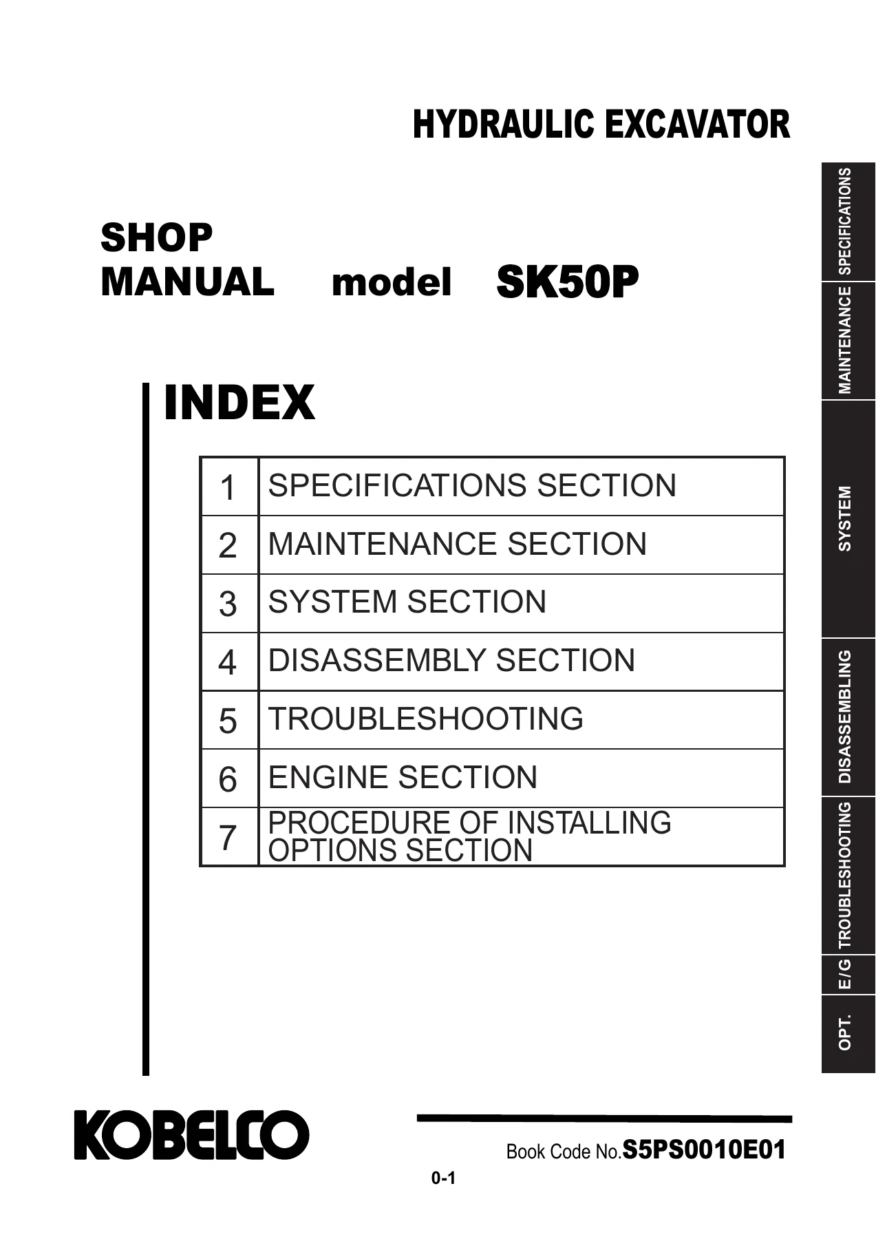
    Kobelco SK50P Hydraulic Excavator Shop Manual S5PS0010E01 PS02-00101~ PDF — PDF page 1 preview
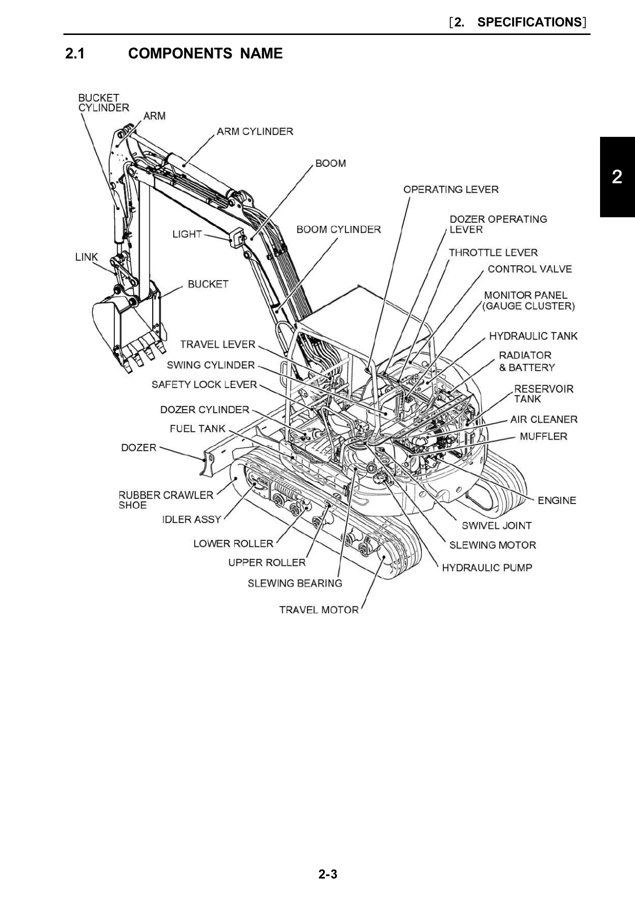
    Kobelco SK50P Hydraulic Excavator Shop Manual S5PS0010E01 PS02-00101~ PDF — PDF page 19 preview
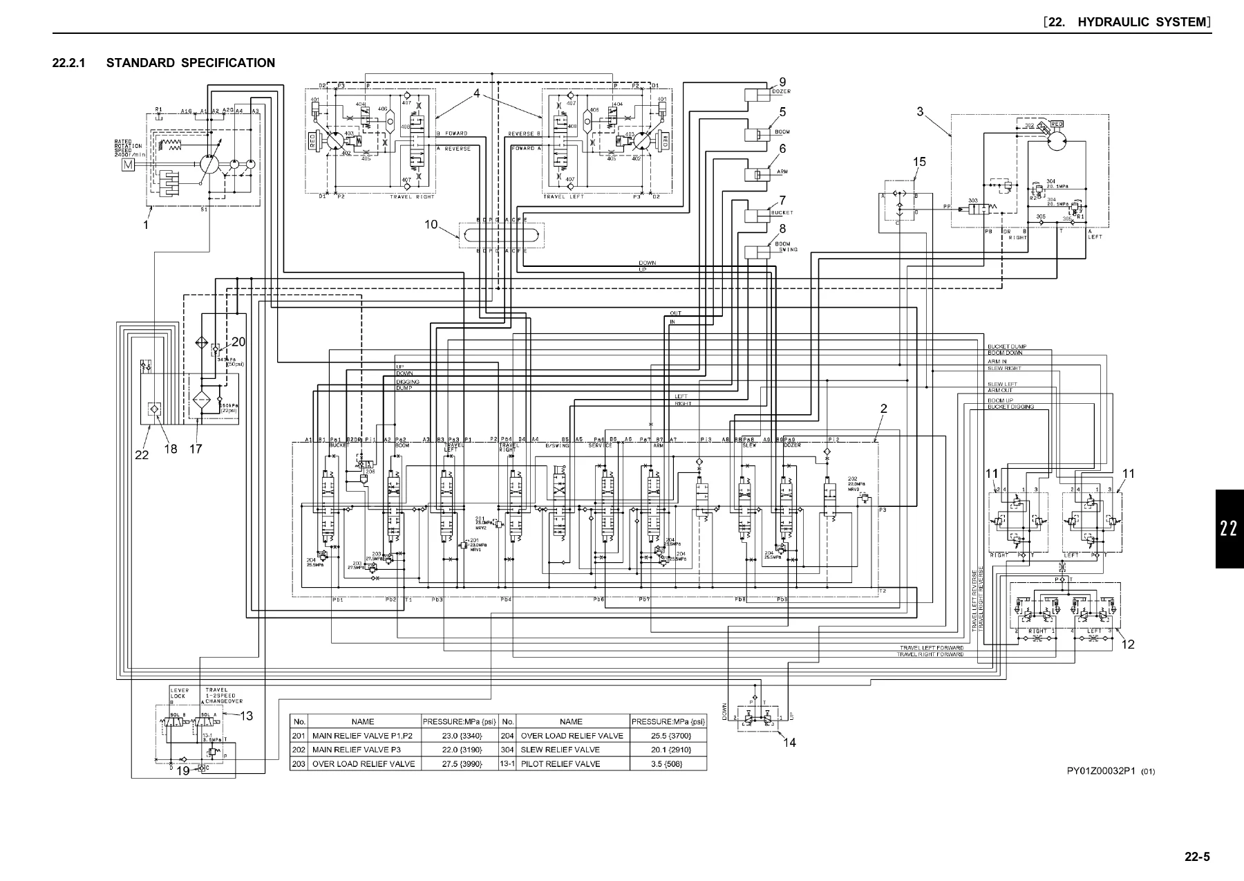
    Kobelco SK50P Hydraulic Excavator Shop Manual S5PS0010E01 PS02-00101~ PDF — PDF page 109 preview

  • Tools
    • Capscrew, nut, joint, hose and tube-fitting torque specifications
    • Screw and tool sizes, plugs and special spanners
    • Special tools, locking/sealing compounds and lifting jigs
  • Standard Maintenance Time Table
    • Attachment, canopy and guard work
    • Upper structure maintenance operations
    • Undercarriage maintenance operations
  • Maintenance Standard and Test Procedure
    • Performance inspection standards
    • Engine speed and hydraulic pressure measurement
    • Travel and slew performance testing
    • Attachment cylinder performance and gravity-drift tests
    • Slew bearing play and crawler tension measurement
  • Hydraulic System
    • Hydraulic circuit functions and component models
    • Neutral, travel, slew, bucket, boom, arm, swing and dozer circuits
    • Combined operating circuits
    • Hydraulic system schematic piping
  • Electrical System
    • Circuit diagrams and harness connection information
    • Electrical equipment and harness lists
    • Component and harness arrangement drawings
    • Detailed harness and cable diagrams
  • Components System
    • Hydraulic pump and pilot valves
    • Control valve
    • Slewing and travel motors
    • Swivel joint and hydraulic cylinders
    • Electrical equipment
  • General Disassembly and Assembly
    • General repair organization and tightening-torque guidance
  • Attachments
    • Bucket, arm, boom, swing and dozer removal and installation
    • Hydraulic cylinder disassembly and assembly
  • Upper Slewing Structure
    • Removal and installation of canopy, guards, tanks, pump, valve, engine, radiator, motor, swivel joint and upper frame
    • Disassembly and assembly of hydraulic pump, control valve, pilot valves, slewing motor and swivel joint
  • Travel System
    • Crawler, rollers, front idler, idler adjuster and sprocket
    • Travel motor and slewing bearing removal and installation
    • Travel motor disassembly and assembly
  • Troubleshooting – Hydraulic System
    • Attachment, travel and slewing operation diagnosis
    • Pump troubleshooting
  • Troubleshooting – Electrical System
    • General electrical faults
    • Attachment and travel operation faults
    • Deceleration faults
  • Troubleshooting – Engine
    • Starting trouble and engine rotation trouble
    • Output drop and other engine trouble
  • Engine
    • TNV-series general service information and periodic maintenance
    • Engine, fuel, cooling and lubrication systems
    • Turbocharger, starter motor and alternator
    • Electric wiring and engine troubleshooting

Taken together, these sections let a technician move from identifying specifications and service limits to understanding system operation, measuring performance, locating faults, removing assemblies and carrying out component repair. The numerous diagrams are especially useful for relating written procedures to hydraulic circuits, wiring, component construction and physical machine locations.

Removal, Installation and Component Repair

The disassembly material provides practical sequences for major SK50P assemblies. Attachment coverage includes bucket removal and installation, arm and boom work, swing bracket and swing cylinder procedures, and dozer removal and installation. The upper slewing structure section extends this approach to the canopy, guards, floor plate, battery, counterweight, hydraulic pump, control valve, solenoid valve, fuel and hydraulic tanks, air cleaner, generator, muffler, control stand, starter, radiator, engine, pilot valve, slewing motor, swivel joint and upper frame.

Complete PDF Bookmark Tree

Complete Bookmarks

The complete bookmarks in the “Kobelco SK50P Hydraulic Excavator Shop Manual S5PS0010E01 PS02-00101~ PDF” are as follows:

TNV_DI_SM_(0BTNV-G00101).pdfp. 1
Table of Contentsp. 553
Introductionp. 555
Yanmar Warrantiesp. 557
Yanmar Limited Warrantyp. 559
What is Covered by this Warranty?p. 559
How Long is the Warranty Period?p. 559
What the Engine Owner Must Do:p. 559
To Locate an Authorized Yanmar Industrial Engine Dealer or Distributor:p. 560
What Yanmar Will Do:p. 560
What is Not Covered by this Warranty?p. 560
Warranty Limitations:p. 561
Warranty Modifications:p. 561
Questions:p. 561
Retail Purchaser Registrationp. 561
Emission System Warrantyp. 562
Yanmar Co., Ltd. Limited Emission Control System Warranty – USA Onlyp. 562
Your Warranty Rights and Obligations:p. 562
Californiap. 562
Manufacturer’s Warranty Period:p. 562
Warranty Coverage:p. 563
Warranted Parts:p. 563
Exclusions:p. 564
Owner’s Warranty Responsibilities:p. 564
Safetyp. 565
Safety Statementsp. 567
Safety Precautionsp. 568
General Service Informationp. 589
Component Identificationp. 591
Location of Labelsp. 593
Engine Nameplate (Typical)p. 594
Emission Control Regulationsp. 594
EPA / ARB Regulations – USA Onlyp. 594
Emission Control Labelsp. 594
The 97/68/EC Directive Certified Enginesp. 595
Engine Familyp. 595
Function of Major Engine Componentsp. 596
MAIN ELECTRONIC CONTROL COMPONENTS AND FEATURESp. 597
Function of Cooling System Componentsp. 599
Diesel Fuelp. 600
Diesel Fuel Specificationsp. 600
Additional Technical Fuel Requirementsp. 600
Bio-Diesel Fuelsp. 600
Filling The Fuel Tankp. 601
Priming the Fuel Systemp. 603
Engine Oilp. 603
Engine Oil Specificationsp. 603
Service Categoriesp. 603
Definitionsp. 603
Additional Technical Engine Oil Requirements:p. 604
Engine Oil Viscosityp. 604
Checking Engine Oilp. 604
Adding Engine Oilp. 605
Engine Oil Capacity (Typical)p. 605
Engine Coolantp. 606
Engine Coolant Specificationsp. 607
Additional Technical Coolant Specifications:p. 607
Alternative Engine Coolantp. 607
Filling Radiator with Engine Coolantp. 607
Engine Coolant Capacity (Typical)p. 608
Specificationsp. 609
Description of Model Numberp. 609
Engine Speed Specificationsp. 609
Principal Engine Specificationsp. 611
3TNV82A (~ EPA Tier2)p. 611
3TNV84 (~ EPA Tier2)p. 612
3TNV84T (~ EPA Tier2)p. 613
3TNV88 (~ EPA Tier2)p. 614
4TNV84 (~ EPA Tier2)p. 615
4TNV84T (~ EPA Tier2)p. 616
4TNV88 (~ EPA Tier2)p. 617
4TNV94L (~ EPA Tier2)p. 618
4TNV98 (~ EPA Tier2)p. 619
4TNV98T (~ EPA Tier2)p. 620
4TNV106 (~ EPA Tier2)p. 621
4TNV106T (~ EPA Tier2)p. 622
Engine Service Standardsp. 633
Tightening Torques for Standard Bolts and Nutsp. 634
Abbreviations and Symbolsp. 636
Abbreviationsp. 636
Symbolsp. 636
Unit Conversionsp. 637
Unit Prefixesp. 637
Units of Lengthp. 637
Units of Volumep. 637
Units of Massp. 637
Units of Forcep. 637
Units of Torquep. 637
Units of Pressurep. 637
Units of Powerp. 637
Units of Temperaturep. 637
Periodic Maintenancep. 639
Before You Begin Servicingp. 641
Introductionp. 654
The Importance of Periodic Maintenancep. 654
Performing Periodic Maintenancep. 654
Yanmar Replacement Partsp. 654
Required EPA / ARB Maintenance – USA Onlyp. 654
EPA / ARB Installation Requirements – USA Onlyp. 654
Periodic Maintenance Schedulep. 655
Periodic Maintenance Proceduresp. 658
After Initial 50 Hours of Operationp. 658
Replace Engine Oil and Engine Oil Filterp. 658
Check and Adjust Cooling Fan V-Beltp. 660
Every 50 Hours of Operationp. 662
Drain Fuel Filter / Water Separatorp. 662
Check Batteryp. 664
Every 250 Hours of Operationp. 665
Drain Fuel Tankp. 665
Replace Engine Oil and Engine Oil Filterp. 666
Check and Clean Radiator Finsp. 667
Check and Adjust Cooling Fan V-Beltp. 668
Check and Adjust the Governor Lever and Engine Speed Control (This does not apply to the following electronically controlled engines: 4TNV84T- Z, 4TNV98-E, Z, and 4TNV98T-Z.)p. 668
Clean Air Cleaner Elementp. 669
Every 500 Hours of Operationp. 670
Replace Air Cleaner Elementp. 670
Replace Fuel Filterp. 671
Clean Fuel Filter / Water Separatorp. 672
Every 1000 Hours of Operationp. 674
Drain, Flush and Refill Cooling System With New Coolantp. 674
Adjust Intake / Exhaust Valve Clearancep. 677
Every 1500 Hours of Operationp. 677
Inspect, Clean and Test Fuel Injectorsp. 677
Inspect Turbocharger (Blower Wash as Necessary) – 3TNV84T, 4TNV98T, 4TNV84T, and 4TNV106T, 3TNV84T-Z, 4TNV84T-Z, 4TNV98T-Zp. 678
Inspect, Clean and Test EGR Valvep. 678
Inspect and Clean EGR Lead Valvep. 678
Clean EGR Coolerp. 678
Inspect Crankcase Breather Systemp. 678
Every 2000 Hours of Operationp. 680
Check and Replace Fuel Hoses and Engine Coolant Hosesp. 680
Lap the Intake and Exhaust Valvesp. 680
Enginep. 681
Before You Begin Servicingp. 683
Introductionp. 686
Cylinder Head Specificationsp. 686
Adjustment Specificationsp. 686
Cylinder Headp. 686
Intake / Exhaust Valve and Guidep. 687
Push Rodp. 689
Rocker Arm and Shaftp. 689
Valve Springp. 690
Camshaft and Timing Gear Train Specificationsp. 691
Camshaftp. 691
Idler Gear Shaft and Bushingp. 693
Timing Gear Backlashp. 693
Crankshaft and Piston Specificationsp. 694
Crankshaftp. 694
Thrust Bearingp. 695
Pistonp. 696
Piston Ringp. 698
Connecting Rodp. 702
Connecting Rod Small Endp. 702
Connecting Rod Big Endp. 702
Tappetp. 703
Cylinder Block Specificationsp. 704
Cylinder Blockp. 704
Special Torque Chartp. 705
Torque for Bolts and Nutsp. 705
Special Service Toolsp. 708
Measuring Instrumentsp. 712
2-Valve Cylinder Headp. 714
2-Valve Cylinder Head Componentsp. 714
Components of a two-valve cylinder headp. 715
Disassembly of 2-Valve Cylinder Headp. 716
Removing the glow plugsp. 717
Removal of Valve Coverp. 717
Removal of Rocker Arm Assemblyp. 718
Disassembly of Rocker Arm Assemblyp. 718
Removal of Cylinder Headp. 718
Removal of Intake / Exhaust Valvesp. 719
Removal of Valve Guidesp. 720
Cleaning of Cylinder Head Componentsp. 720
Inspection of Cylinder Head Componentsp. 720
Inspection of Push Rodsp. 721
Inspection of Rocker Arm Assemblyp. 721
Inspection of Valve Guidesp. 721
Inspection of Cylinder Headp. 722
Inspection of Intake and Exhaust Valvesp. 722
Inspection of Valve Springsp. 724
Reassembly of Cylinder Headp. 724
Reassembly of Valve Guidesp. 724
Reassembly of Intake and Exhaust Valvesp. 725
Reassembly of Cylinder Headp. 726
Reassembly of Rocker Arm Reassemblyp. 727
Reassembly of the Valve Coverp. 728
4-Valve Cylinder Headp. 729
4-Valve Cylinder Head Componentsp. 729
Disassembly of 4-Valve Cylinder Headp. 730
Removal of Valve Coverp. 732
Removal of Rocker Arm Assemblyp. 733
Disassembly of Rocker Arm Assemblyp. 733
Removal of Cylinder Headp. 734
Removal of Intake and Exhaust Valvesp. 734
Removal of Valve Guidesp. 735
Cleaning of Cylinder Head Componentsp. 735
Inspection of Cylinder Head Componentsp. 736
Inspection of Push Rodsp. 736
Inspection of Rocker Arm Assemblyp. 736
Inspection of Valve Guidesp. 737
Inspection of Cylinder Headp. 737
Inspection of Intake and Exhaust Valvesp. 738
Inspection of Valve Springsp. 740
Inspection of Valve Bridgesp. 740
Reassembly of Cylinder Headp. 741
Reassembly of Valve Guidesp. 741
Reassembly of Intake and Exhaust Valvesp. 741
Reassembly of Cylinder Headp. 742
Reassembly of Rocker Arm Assemblyp. 743
Reassembly of the Valve Coverp. 745
Measuring and Adjusting Valve Clearancep. 746
2-Valve Cylinder Headsp. 747
4-Valve Cylinder Headsp. 748
Crankshaft and Camshaft Componentsp. 751
Disassembly of Enginep. 752
Disassembly of Camshaft and Timing Componentsp. 753
Removal of Timing Gear Case Coverp. 753
Checking Timing Gear Backlashp. 753
Measuring Idler Gear-to-Crankshaft Gear Backlashp. 754
Measuring Idler Gear-to-Camshaft Gear Backlashp. 754
Removal of Timing Gearsp. 754
Removal of Oil Panp. 755
Removal of Camshaftp. 756
Removal of Gear Case or Front Platep. 757
Disassembly of Crankshaft and Piston Componentsp. 758
Removal of Pistonsp. 758
Removal of Crankshaftp. 760
Inspection of Crankshaft and Camshaft Componentsp. 762
Replacement of Crankshaft Oil Sealsp. 762
Measure Crankshaft Bearing Oil Clearancep. 763
Inspection of Cylinder Blockp. 763
Inspection of Pistons, Piston Rings and Wrist Pinp. 763
Inspection of Connecting Rodp. 765
Inspection of Tappetsp. 765
Inspection of Crankshaftp. 766
Inspection of Camshaftp. 767
Inspection of Camshaft Bushing and Boresp. 767
Inspection of Idler Gear and Shaftp. 767
Honing and Boringp. 768
Reassembly of Crankshaft and Piston Componentsp. 769
Reassembly of Pistonsp. 769
Installation of Crankshaftp. 772
Installation of Pistonsp. 773
Reassembly of Camshaft and Timing Componentsp. 775
Installation of Gear Case or Front Platep. 775
Installation of Camshaftp. 776
Installation of Timing Gearsp. 777
Installation of Gear Case Coverp. 777
Installation of Oil Panp. 778
Final Reassembly of Enginep. 779
EGR systemp. 780
EGR systemp. 780
EGR systemp. 782
4TNV98-E, 4TNV98-Zp. 784
4TNV84T-Z, 4TNV98T-Zp. 784
Inspecting/cleaning EGR related componentsp. 785
EGR Valvep. 785
EGR valve operation checksp. 785
Cleaning the EGR valvesp. 786
Lead valvesp. 786
Precautions for installationp. 787
EGR coolerp. 787
EGR pipe and other connecting elbowsp. 787
Installing EGR related components/partsp. 788
Fuel Systemp. 789
Before You Begin Servicingp. 791
Introductionp. 796
Fuel Injection Pumpp. 796
Stop Solenoidp. 797
Cold Start Devicep. 797
Trochoid Fuel Pumpp. 798
Electronically controlled governorp. 798
Fuel System Specificationsp. 799
Special Torque Chartp. 799
Test and Adjustment Specificationsp. 800
Special Service Toolsp. 801
Measuring Instrumentsp. 801
Fuel System Diagramp. 802
Fuel System Componentsp. 803
2-Valve Cylinder Headp. 803
4-Valve Cylinder Headp. 805
Fuel Injection Pumpp. 807
Removal of Fuel Injection Pumpp. 807
Installation of Fuel Injection Pumpp. 812
Checking and Adjusting Fuel Injection Timingp. 818
Determining the Fuel Injection Timing Specificationp. 818
(6.8 X 2) = 13.6 + 4 = 17.6˚ Fuel injection Timingp. 818
Checking Fuel Injection Timingp. 819
Adjusting Fuel Injection Timingp. 822
Fuel Injectorsp. 823
Removal of Fuel Injectorsp. 823
2-Valve Cylinder Headp. 823
4-Valve Cylinder Headp. 824
Testing of Fuel Injectorsp. 826
Disassembly and Inspection of Fuel Injectorsp. 827
Adjusting Fuel Injector Pressurep. 829
Reassembly of Fuel Injectorsp. 829
Installation of the Fuel Injectorsp. 830
2-Valve Cylinder Headp. 830
4-Valve Cylinder Headp. 830
Fuel injection system (for a four-valve cylinder head)p. 831
Cooling Systemp. 833
Before You Begin Servicingp. 835
Introductionp. 838
Cooling System Diagramp. 838
Engine Coolant Pump Componentsp. 839
Engine Coolant System Checkp. 840
Engine Coolant Pumpp. 840
Removal of Engine Coolant Pumpp. 840
Disassembly of Engine Coolant Pumpp. 842
Cleaning and Inspectionp. 842
Temperature Switchp. 842
Water temperature sensorp. 842
Thermostatp. 843
Radiator Capp. 843
Reassembly of Engine Coolant Pumpp. 843
Installation of Engine Coolant Pumpp. 844
Lubrication Systemp. 847
Before You Begin Servicingp. 849
Introductionp. 851
Oil Pump Service Informationp. 851
Lubrication System Diagramp. 854
Checking Engine Oil Pressurep. 855
Trochoid Oil Pumpp. 855
3TNV82A to 4TNV88 Oil Pump Componentsp. 855
Disassembly of Oil Pumpp. 856
Cleaning and Inspectionp. 857
Check Outer Rotor Outside Clearancep. 857
Outer Rotor to Inner Rotor Tip Clearancep. 857
Check Outer Rotor Side Clearancep. 858
Check Inner Rotor and Gear Boss Clearancep. 858
Reassembly of Oil Pumpp. 858
Trochoid Oil Pumpp. 859
3TNV82A-B, 3TNV88-B, 3TNV88- U, 4TNV88-B4TNV88-U, 3TNV84T-Z, 4TNV84T-Z Oil Pump Componentsp. 859
Disassembly of Oil Pumpp. 860
Cleaning and inspectionp. 860
Check Outer Rotor Outside Clearancep. 860
Outer Rotor to Inner Rotor Tip Clearancep. 861
Check Outer Rotor Side Clearancep. 861
Check Rotor Shaft Clearancep. 861
Reassembly of Oil Pumpp. 862
Trochoid Oil Pumpp. 863
4TNV94L/98/106 Oil Pump Componentsp. 863
Disassembly of Oil Pumpp. 863
Cleaning and Inspectionp. 864
Check Outer Rotor Outside Clearancep. 864
Outer Rotor to Inner Rotor Tip Clearancep. 864
Check Outer Rotor Side Clearancep. 864
Check Rotor Shaft Clearancep. 865
Reassembly of Oil Pumpp. 865
Turbochargerp. 867
Before You Begin Servicingp. 869
Introductionp. 871
Specificationsp. 871
Turbocharger Service Informationp. 871
Troubleshootingp. 872
Excessive Exhaust Smokep. 872
Generates White Smokep. 873
Sudden Oil Decreasep. 873
Decrease in Outputp. 873
Poor (Slow) Response (Starting) of Turbochargerp. 873
Abnormal Sound or Vibrationp. 873
Turbocharger Componentsp. 874
Turbocharger Component Functionsp. 876
Theory of Operationp. 877
Turbinep. 877
Compressorp. 877
Bearingsp. 877
Compressor Side Sealing Mechanismp. 877
Waste Gate Modulationp. 877
Waste Gate Controlp. 877
Washing Procedurep. 878
Periodic Inspectionp. 879
Visual Inspectionp. 879
Inspection of Rotor Rotationp. 879
Inspection of Rotor Playp. 879
Removal of Turbochargerp. 879
Checking Rotor Playp. 880
To Check Rotor End Play:p. 880
To Check Rotor Run-out:p. 880
Waste Gate Valve Testp. 880
Waste Gate Actuator Leak Testp. 881
Installation of Turbochargerp. 881
Starter Motorp. 883
Before You Begin Servicingp. 885
Introductionp. 887
Starter Motor Informationp. 887
3TNV82A to 4TNV88 – Standard and Optionalp. 887
Starter Motor Specificationsp. 889
Starter Motor Troubleshootingp. 890
Starter Motor Componentsp. 891
Starter Motorp. 892
Removal of Starter Motorp. 892
Disassembly of Starter Motorp. 892
Cleaning and Inspectionp. 894
Armaturep. 894
Field Coilp. 896
Magnetic Switchp. 897
Pinion Clutch Assemblyp. 898
Reassembly of Starter Motorp. 899
Check Pinion Projection Lengthp. 900
No-Load Testp. 901
Installation of Starter Motorp. 902
Alternatorp. 903
Before You Begin Servicingp. 905
Introductionp. 908
Dynamo and Alternator Informationp. 908
3TNV82A to 4TNV106T – Standard and Optional Dynamosp. 908
3TNV82A to 4TNV106T – Standard and Optional Alternatorsp. 908
Alternator Specificationsp. 909
Dynamo Specificationsp. 909
Alternator Troubleshootingp. 910
Alternator Componentsp. 911
Alternator Wiring Diagramp. 912
Alternator Standard Outputp. 913
Alternatorp. 914
Removal of Alternatorp. 914
Disassembly of Alternatorp. 914
Reassembly of Alternatorp. 916
Installation of Alternatorp. 918
Dynamo Component Locationp. 919
Dynamo Wiring Diagramp. 920
Operation of Dynamop. 920
Dynamo Standard Outputp. 921
Testing of Dynamop. 922
Testing Stator Coil Continuityp. 922
Testing Stator Coil Short-to-Groundp. 922
Testing Dynamo Regulated Outputp. 922
Dynamop. 922
Removal of Dynamop. 922
Disassembly of Dynamop. 923
Reassembly of Dynamop. 923
Installation of Dynamop. 924
Troubleshootingp. 925
Special Service Toolsp. 926
Troubleshooting By Measuring Compression Pressurep. 927
Compression Pressure Measurement Methodp. 927
Measured Value and Troubleshootingp. 930
Quick Reference Table For Troubleshootingp. 930
Failure Diagnosis Tablep. 931
Electrical Wiringp. 937

Component overhaul coverage is equally substantial. Hydraulic cylinder procedures address preparation, disassembly, inspection, assembly and post-repair checks. Separate sections cover hydraulic pump, control valve, attachment pilot valve, travel pilot valve, slewing motor, swivel joint and travel motor disassembly and assembly. The travel-system chapter also deals with crawler components, rollers, front idler, adjuster, sprocket and slewing bearing.

Diagnostic and Troubleshooting Reference

The Kobelco SK50P Hydraulic Excavator Shop Manual S5PS0010E01 PS02-00101~ PDF provides both test procedures and symptom-based troubleshooting. Hydraulic diagnosis includes attachment operational problems, slow or weak travel, travel deviation, slewing failure or reduced performance, and pump-related problems. Electrical troubleshooting includes starting faults, horn and work-light problems, hourmeter and gauge faults, loss of attachment controls, two-speed travel switching problems and deceleration-control faults. Engine troubleshooting addresses starting difficulties, engine rotation problems, reduced output and other engine-related symptoms.

The engine portion incorporates a Yanmar TNV DI service manual that covers a wider TNV engine family, including 4TNV88 variants, rather than being written exclusively for the SK50P engine. The SK50P-specific sections of the shop manual identify the machine’s engine as 4TNV88-BXPYBE (EDM-4TNV88), so applicability should be checked against the model-specific information when using the broader TNV engine material.

Repair the SK50P with the Procedures and Data in One Manual

This Kobelco SK50P Hydraulic Excavator Shop Manual S5PS0010E01 PS02-00101~ PDF supports work ranging from specification checks and performance testing to hydraulic and electrical diagnosis, attachment service, major assembly removal, component disassembly and reassembly, travel-system repair and engine servicing. Having the prescribed procedures, diagrams, measurements, service standards and tightening information available during a repair helps technicians inspect components against defined values and follow the documented sequence instead of relying on memory or trial and error.

Delivered as an instant PDF after payment, there is no physical book and no shipping delay. Open the manual on a computer, tablet or phone, keep it available beside the machine during service work, or print the pages you need for the job.

Reviews

There are no reviews yet.

Be the first to review “Kobelco SK50P Hydraulic Excavator Shop Manual S5PS0010E01 PS02-00101~ PDF”

What Our Customers Say

★★★★★ Live reviews from customers
Loading customer reviews...
0
    0
    Your Cart
    Your cart is emptyReturn to Shop
    🛒
    Recently Purchased
    🕒 verified order