
Komatsu PC400LC-8 Hydraulic Excavator Shop Manual – A88001 and Up (CEBM018801)
Original price was: $49.95.$29.95Current price is: $29.95.
928-page Komatsu PC400LC-8 hydraulic excavator shop manual for serial numbers A88001 and up. Covers specifications, hydraulic and electrical systems, standard values, testing and adjusting, troubleshooting, disassembly and assembly, plus hydraulic and electrical diagrams.
Description
Komatsu PC400LC-8 Hydraulic Excavator Shop Manual – A88001 and Up (CEBM018801)
The Komatsu PC400LC-8 Hydraulic Excavator Shop Manual – A88001 and Up (CEBM018801) is a comprehensive 928-page technical workshop reference for the PC400LC-8 hydraulic excavator with serial numbers A88001 and up. Issued by Komatsu America Corp. in December 2007, the manual is organized around machine specifications, structure and function, maintenance standards, standard values, testing and adjustment, troubleshooting, disassembly and assembly, and machine diagrams. It is written for service work where component identification, correct measurements, hydraulic and electrical diagnosis, removal and installation procedures, and repair limits need to be checked against the machine-specific information.
File Details
- Manual type: Shop Manual
- Brand / model: Komatsu PC400LC-8 Hydraulic Excavator
- Serial coverage: PC400LC-8 A88001 and up
- Engine shown in specifications: SAA6D125E-5
- Language: English
- Page count: 928 pages
- File format: PDF
- Publication number: CEBM018801
- Date: December 2007
Machine-specific workshop information
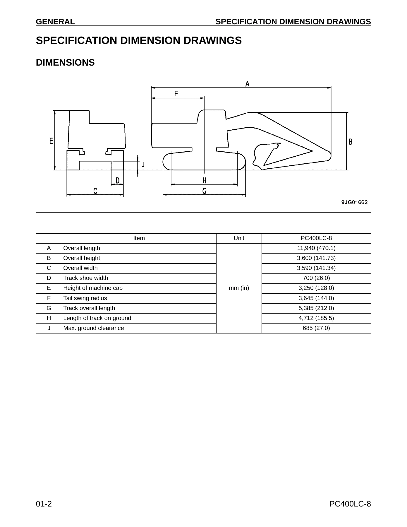
This PC400LC-8 shop manual goes well beyond basic maintenance data. The General section provides specification dimension drawings, working ranges, machine specifications, component weights, and fuel, coolant, and lubricant information. The specifications identify the SAA6D125E-5 engine and include engine performance data, the 24 V starting and charging system, undercarriage configuration, hydraulic pump information, travel and swing motor information, and boom, arm, and bucket cylinder dimensions. Capacity information includes the engine oil pan, swing machinery case, final drive cases, hydraulic system, fuel tank, and cooling system.
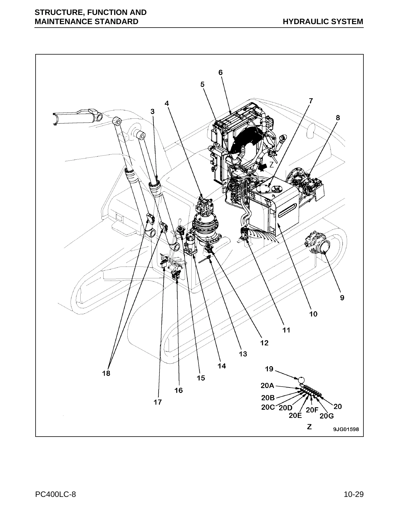
The Structure, Function and Maintenance Standard material explains how major PC400LC-8 systems are built and how they operate. It covers the power train, final drive, swing machinery, swing circle, track frame and undercarriage, the hydraulic pump and control valve system, Closed Center Load Sensing System (CLSS), pressure compensation, regeneration circuits, travel and swing control, PPC and solenoid control, cylinders, work equipment, electrical control, sensors, the machine monitor, and KOMTRAX components. Component drawings, sectional views, hydraulic circuit illustrations, clearances, repair limits, spring specifications, pressure settings, and tightening torques are used throughout this part of the manual.
For diagnosis and setup work, the manual supplies standard-value tables and dedicated testing procedures rather than relying only on general descriptions. Engine-related values include operating speeds, intake pressure, exhaust temperature and smoke, valve clearance, compression pressure, blow-by pressure, and oil pressure. Chassis-related tables cover hydraulic performance, work equipment speed and drift, travel and swing behavior, pump delivery, and other measurable conditions used to compare machine performance with standard or permissible values.
Chapters Covered
- 01 GENERAL
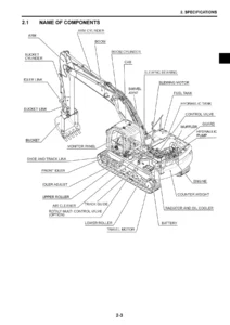
- Specification dimension drawings, dimensions and working ranges
- Machine specifications
- Weight table
- Fuel, coolant and lubricants
- 10 STRUCTURE, FUNCTION AND MAINTENANCE STANDARD
- Engine related parts, radiator, oil cooler and aftercooler
- Power train, final drive, sprocket, swing machinery and swing circle
- Undercarriage and frame, track frame, recoil spring, idler, carrier roller, track roller and triple grouser shoe
- Hydraulic piping, hydraulic tank and filter, hydraulic pump, LS valve, PC valve and LS(PC)-EPC valve
- Control valve and CLSS (Closed Center Load Sensing System)
- Unload, bypass, pressure compensation, regeneration, merge-divider, drift preventive, quick return, relief and attachment-control circuits
- PPC valves, solenoid valve, accumulator, return oil filter and center swivel joint
- Travel motor, brake valve, swing motor and reverse prevention valve
- Boom, arm and bucket hydraulic cylinders
- Work equipment and component dimensions
- Air conditioner piping
- Electrical and electronic control systems, sensors, pump controller, machine monitor and KOMTRAX terminal system
- 20 STANDARD VALUE TABLES
- Engine-related standard and permissible values
- Chassis-related standard and permissible values for travel, swing, work equipment and hydraulic performance
- 30 TESTING AND ADJUSTING
- Service tools
- Engine checks including boost pressure, blow-by, compression, oil pressure, engine speed, fuel-system checks and valve clearance
- Belt tension, swing circle bearing clearance and track shoe tension
- Work equipment, swing and travel circuit oil-pressure checks
- Control circuit, pump PC control, pump LS control, solenoid and PPC valve pressure checks
- Work equipment PPC and swing PPC play adjustment
- Hydraulic drift diagnosis, residual-pressure release, oil-leakage measurement and air bleeding
- Diode inspection and electrical-system preparation
- Machine monitor ordinary, operator and service functions, abnormality records, maintenance settings and adjustments
- KOMTRAX terminal, GPS, communication and modem settings
- PM Clinic Service
- 40 TROUBLESHOOTING
- Failure codes, fuse locations and fuse-box connection information
- General troubleshooting procedure, checks and connector information
- Electrical-system E-mode troubleshooting
- Hydraulic and mechanical H-mode troubleshooting
- Problems involving work equipment power and speed, travel, steering, swing, drift and attachment circuits
- Machine monitor, sensor, solenoid, controller, wiring and communication-related diagnostic paths
- 50 DISASSEMBLY AND ASSEMBLY
- How to read the section, special tools and tool sketches
- HD30 and DT connector repair procedures
- Engine component references and cooling-system components
- Radiator, hydraulic oil cooler and aftercooler removal and installation
- Engine and hydraulic oil pump removal and installation
- Drive assembly removal, disassembly, assembly and installation
- Swing motor, swing machinery and swing circle procedures
- Carrier roller, track roller, idler and undercarriage service procedures
- Center swivel joint, hydraulic tank, control valve and hydraulic-system component procedures
- Hydraulic cylinders and work equipment removal, installation and assembly work
- Electrical-system service procedures
- 90 OTHER
- Hydraulic diagram
- Electrical diagram
Taken together, these chapters give a technician a machine-specific path from understanding system operation to measuring actual performance, isolating faults, judging wear or service limits, and carrying out component removal, installation, disassembly and assembly. The cross-references between structure/function, standard values, testing and adjusting, troubleshooting, and repair procedures are especially useful when a symptom needs to be traced to a hydraulic, mechanical or electrical cause before parts are removed.
Hydraulic, electrical and diagnostic depth
A major portion of the Komatsu PC400LC-8 Hydraulic Excavator Shop Manual – A88001 and Up (CEBM018801) is devoted to the hydraulic system. The manual identifies the HPV160+160(190) variable-displacement piston pump arrangement and explains pump delivery control, LS and PC valve operation, the control valve, CLSS, pressure compensation, boom and arm regeneration, merge-divider operation, self-pressure reduction, travel junction control, boom and arm drift prevention, quick return, relief and safety-suction valves, and attachment circuit selection. Diagrams show oil paths and valve states so pressure readings and symptoms can be related to actual circuit operation.
Electrical and electronic material covers wire codes, control-system structure, sensors, switches, engine and pump control, machine-monitor functions and diagnostic records. The troubleshooting section includes failure-code information, fuse locations, connector references, E-mode electrical troubleshooting and H-mode hydraulic/mechanical troubleshooting. This makes the manual useful for faults that cross system boundaries, such as a machine that lacks hydraulic power, travels slowly, will not swing correctly, shows monitor or sensor abnormalities, or has attachment-control problems.
Disassembly, assembly and service measurements
The repair section combines removal and installation sequences with component-specific disassembly and assembly instructions. Procedures include precautions, component weights where needed for lifting, specified sealants or lubricants, oil refill information, tightening torques and references to testing steps such as bleeding air or releasing residual hydraulic pressure. Separate standard and maintenance data elsewhere in the manual provide the clearances, wear limits and judgement criteria needed before deciding whether a part can be reused, repaired or replaced.
Examples of the documented service scope include the drive assembly, swing motor and swing machinery, swing circle, undercarriage rollers and idler, hydraulic tank, center swivel joint, control valve, hydraulic cylinders and work equipment. The manual also contains connector repair procedures and electrical-system service material, allowing mechanical, hydraulic and electrical work to be approached within the same PC400LC-8 chassis reference.
Coverage note
The manual itself explains that Komatsu shop information is divided among chassis, engine, electrical and attachment volumes to avoid duplication. Within this PC400LC-8 volume, certain engine-component removal, installation, disassembly and assembly procedures direct the technician to the separate engine shop manual, and engine-system S-mode troubleshooting is also identified as being in the engine shop manual. This PDF therefore provides the extensive PC400LC-8 chassis, hydraulic, electrical, testing, troubleshooting and repair coverage listed above, while some engine-specific procedures require the corresponding engine shop manual.
Repair and diagnose the PC400LC-8 with the correct reference
Use the Komatsu PC400LC-8 Hydraulic Excavator Shop Manual – A88001 and Up (CEBM018801) when you need to identify systems, verify specifications, measure pressures and performance, follow diagnostic paths, check repair limits, or carry out removal and installation work on the PC400LC-8 covered from serial A88001 and up. Having the model-specific procedures, standard values, circuit diagrams, tightening information and component illustrations together helps reduce guesswork and supports repairs that follow the specified sequence and judgement criteria.
Your manual is supplied as an instant PDF download after payment. There is no physical book and no shipping delay. Open it on a computer, tablet or phone, keep it available in the workshop, and print the pages you need for the job.

Reviews
There are no reviews yet.