★ TRUSTED BY 321,897+ PROFESSIONALS WORLDWIDE
🏒
Trusted Business
Verified & Licensed
πŸ›‘οΈ
Virus Free Files
100% Safe Downloads
πŸ”’
Secure Payment
SSL Protected
⚑
Instant Delivery
Available Immediately
Sale!

Doosan DX140LC Shop Manual K1027955AE-1 – Serial 5457 & Up Excavator Repair PDF

Original price was: $39.95.Current price is: $24.95.

Complete Doosan DX140LC Shop Manual (K1027955AE-1) covering serial numbers 5457 and up. This PDF service and repair guide includes engine, hydraulics, electrical, undercarriage, and attachment procedures for the DX140LC excavator.

⚑
Instant PDF Download
Available immediately
πŸ’Ύ
Save to Your Device
Download & keep forever
πŸ›‘οΈ
Antivirus Scanned
100% virus-free
🌍
Trusted Worldwide
175,000+ customers

Description

Doosan DX140LC Shop Manual K1027955AE-1

This Doosan DX140LC Shop Manual is the complete service and repair guide for DX140LC excavators from serial number 5457 and up. Published under document number K1027955AE-1, this PDF workshop manual gives technicians, mechanics, and equipment owners direct access to the same procedures used for professional maintenance, troubleshooting, and overhaul of the DX140LC machine.

Whether you are servicing a single excavator or managing a fleet, the Doosan DX140LC Shop Manual provides the detailed, system-by-system information needed to diagnose faults, perform repairs, and maintain the machine to specification. Every major assembly is covered, from the DL06 engine and hydraulic pumps to the swing bearing, travel motors, control valves, and electrical system.

File Details

  • Manual Type: Shop Manual (Service & Repair)
  • Brand: Doosan
  • Model: DX140LC
  • Document Number: K1027955AE-1
  • Serial Number Range: 5457 and Up
  • Language: English
  • File Format: PDF
  • Page Count: Approximately 910 pages

Chapters Covered

The Doosan DX140LC Shop Manual is organized into major sections that mirror the machine’s structure and systems. The table of contents includes:

  • Safety – Track Excavator Safety
  • Specifications – Specification for DX140LC
  • General Maintenance – General Maintenance Procedures, Standard Torques
  • Upper Structure – Cabin (NON-ROPS), Cabin (ROPS), Counterweight, Fuel Tank, Fuel Transfer Pump (Opt), Swing Bearing, Swing Reduction Gear
  • Lower Structure and Chassis – Track Assembly
  • Engine and Drive Train – Drive Coupling (Main Pump)
  • Hydraulics – Hydraulic System Troubleshooting, Testing and Adjustment, Accumulator, Center Joint (Swivel), Cylinders, Swing Motor, Travel Motor, Main Pump, Main Control Valve, Remote Control Valve (Work Lever / Joystick), Travel Control Valve (with Damper), Solenoid Valve Assembly, Breaker EPPR Valve (Opt), Hydraulic Schematic (DX140LC)
  • Electrical System – Electrical System (NON-ROPS), Electrical System (ROPS), Electrical Schematic (NON-ROPS), Electrical Schematic (ROPS)
  • Attachments – Boom and Arm, Bucket

The depth of coverage in this DX140LC shop manual goes well beyond routine maintenance. Each section includes component descriptions, theory of operation, removal and installation procedures, disassembly and reassembly steps, inspection criteria, wear limits, torque values, and troubleshooting charts. The hydraulic section alone spans hundreds of pages with detailed circuit explanations, pressure adjustment procedures, and diagnostic tables for the main pump, control valve, swing motor, travel motor, and remote control valve.

What This Doosan DX140LC Shop Manual Enables

With this Doosan DX140LC repair manual on hand, a technician can confidently tackle jobs that would otherwise require guesswork or trial-and-error. The manual supports:

  • Engine and drive train service – Drive coupling removal and installation with precise clearance measurements (Measure H: 3.0 – 7.0 mm) and torque specifications for the DL06 engine application.
  • Hydraulic system diagnosis and repair – Pilot pressure testing, main relief pressure adjustment (330 kg/cmΒ² standard, 350 kg/cmΒ² with pressure up), power mode valve current and pressure settings, pump regulator adjustment, and swing/travel motor overhaul procedures.
  • Electrical troubleshooting – Complete wiring schematics for both NON-ROPS and ROPS configurations, e-EPOS controller diagnostics, self-diagnostic function codes, air conditioner system troubleshooting, wiper and lighting circuits, and audio controller pinouts.
  • Undercarriage work – Track tension adjustment, track shoe and link inspection with wear limits, front idler and roller disassembly/reassembly, and track spring cylinder service.
  • Upper structure repairs – Cabin removal and installation for both ROPS and NON-ROPS versions, counterweight removal with stability warnings, fuel tank service, swing bearing axial and lateral play measurement, and swing reduction gear overhaul.
  • Attachment service – Boom and arm pin specifications, removal and installation procedures, bucket tooth replacement, bucket O-ring service, and attachment reversal.

Why the Doosan DX140LC Shop Manual Matters

The DX140LC is a 14-ton class excavator powered by the DL06 engine, producing 96 PS at 1,850 rpm with a maximum torque of 44.5 kgΒ·m at 1,400 rpm. Its hydraulic system uses two variable displacement axial piston pumps with a total displacement of 63 cc/rev each, operating at a main relief pressure of 330 kg/cmΒ² (4,689 psi) in normal operation and 350 kg/cmΒ² (4,970 psi) with pressure up. The pilot pump is a gear type delivering 15 cc/rev with a relief pressure set at 40 kg/cmΒ².

These are precise specifications. Operating the machine outside themβ€”or attempting repairs without the correct proceduresβ€”can lead to component failure, reduced service life, and costly downtime. The Doosan DX140LC Shop Manual K1027955AE-1 eliminates that risk by providing the exact values, sequences, and precautions required for every major service task.

For example, the manual specifies that the drive coupling Measure H must be set between 3.0 and 7.0 mm to avoid noise and premature wear on the coupling or main pump. It details the pump regulator adjustment process, noting that a 1/4 turn on the larger diameter adjusting screw equals approximately 17 horsepowerβ€”information that is critical when balancing pump output or addressing engine overloading complaints. The swing bearing section explains how to measure axial and lateral play, with the recommendation that checks be made at least twice a year to track wear progression.

The electrical system coverage is equally thorough. The e-EPOS controller self-diagnostic function can be accessed to read fault codes, and the manual provides a complete failure information code table for both machine-side codes (V201 through V230) and engine-side codes (E011 through E101). This allows a technician to pinpoint issues quickly rather than replacing parts blindly.

Complete PDF Bookmark Tree

Complete Bookmarks

The complete bookmarks in the β€œDoosan DX140LC Shop Manual K1027955AE-1 – Serial 5457 & Up Excavator Repair PDF” are as follows:

DX140LC
Table of Contentsp. 7
Safetyp. 9
Track Excavator Safetyp. 11
Safety Precautionsp. 15
Applicable Modelsp. 15
To the Operator of a DOOSAN Excavatorp. 16
Learn Signal Words Used with Safety Alert Symbolp. 18
General Safety Essentialsp. 19
Accessory Applicationsp. 19
Lifting Capacity Rating Configurationp. 19
Location of Safety Labelsp. 20
Summary of Safety Precautions for Lifting in Digging Modep. 21
Unauthorized Modificationsp. 22
General Hazard Informationp. 22
Safety Rulesp. 22
Safety Featuresp. 22
Inside Operator's Cabinp. 23
Clothing and Personal Protective Itemsp. 23
Breathing Masks, Ear Protection May Be Requiredp. 24
Vibration Level Informationp. 24
Recommendations for Limiting Vibrationsp. 24
Mounting and Dismountingp. 25
Fuel, Oil and Hydraulic Fluid Fire Hazardsp. 26
Precautions When Handling Fluids at High Temperaturep. 26
Asbestos Dust Hazard Preventionp. 27
Injury from Work Equipmentp. 27
Fire Extinguisher and First Aid Kitp. 27
Protection from Falling or Flying Objectsp. 28
Attachment Precautionsp. 29
Accumulatorp. 29
Indoor Ventilationp. 29
Emergency Exitp. 30
Emergency Exit (ROPS)p. 30
Before Starting Enginep. 31
Work Site Precautionsp. 31
Checks Before Starting Enginep. 32
Engine Startingp. 32
Before Operating Machinep. 33
Machine Operationp. 34
When Swinging or Changing Direction of Travelp. 34
Travel Precautionsp. 34
Traveling on Slopesp. 35
Prohibited Operationsp. 36
Precautions for Operationp. 37
Avoid High-voltage Cablesp. 37
Roll Over Protective Structure (ROPS) When Required by Local Regulationsp. 38
General ROPS Guidelines for ROPS Certified Cabinsp. 38
ROPS Certificationp. 39
Protecting Cabin from Falling Object (Optional)p. 39
Operate Carefully on Snow, Ice and in Very Cold Temperaturesp. 40
Operations on Slopesp. 41
Parking Machinep. 41
Never Let Anyone Ride on Attachmentp. 41
Maintenancep. 42
Warning Tagp. 42
Clean Before Inspection or Maintenancep. 42
Proper Toolsp. 43
Use of Lightingp. 43
Fire Prevention and Explosion Preventionp. 43
Burn Preventionp. 44
Welding Repairsp. 45
Treatment for Electrical Welding on Body Structurep. 46
Warning for Counterweight and Front Attachment Removalp. 46
Precautions for Removal, Installation, and Storage of Attachmentsp. 47
Precautions When Working on Machinep. 47
Lock Inspection Coversp. 47
Prevention of Crushing and Cuttingp. 48
Track Tension Adjustments Require Cautionp. 48
Supports and Blocking for Work Equipmentp. 48
Action When Abnormality Is Found During Inspectionp. 49
Precautions with High-pressure Lines, Tubes and Hosesp. 49
Waste Materialsp. 50
Batteryp. 51
Battery Hazard Preventionp. 51
Boost Starting or Charging Engine Batteriesp. 52
Towingp. 53
Precautions When Towingp. 53
Shipping and Transportationp. 54
Obey State and Local Over-the-Road Regulationsp. 54
Lifting With Slingp. 54
Specificationsp. 55
Specification for DX140LCp. 57
Safety Precautionsp. 61
Applicable Modelsp. 61
General Descriptionp. 62
Component Locationsp. 62
General Dimensionsp. 64
One – Piece Boomp. 64
Two – Piece Boomp. 65
Working Rangep. 66
One – Piece Boomp. 66
Two – Piece Boomp. 67
General Specificationsp. 68
Engine Performance Curves (Per DIN6270 Standard)p. 70
Approximate Weight of Workload Materialsp. 72
Performance Testsp. 74
Excavator Performance Standardsp. 75
Test Conditionsp. 75
Travel Speed and Travel Motor Balance (Steering Deviation) Testsp. 75
Speed Testp. 75
Travel Deviationp. 77
Swing Speed and Deceleration Force Testp. 77
Swing Speed Testp. 77
Swing Deceleration Force Testp. 78
Cylinder Performance Testsp. 79
Boom Cylinders Testp. 79
Arm Cylinder Testp. 79
Bucket Cylinder Testp. 79
Hydraulic Cylinder Natural Drop Testp. 79
Travel Motor Jack-up Testp. 80
General Maintenancep. 81
General Maintenance Proceduresp. 83
Safety Precautionsp. 87
Applicable Modelsp. 87
Welding Precautions and Guidelinesp. 88
Hydraulic System – General Precautionsp. 89
Maintenance Service and Repair Procedurep. 91
General Precautionsp. 91
Hydraulic System Cleanliness and Oil Leaksp. 92
Maintenance Precautions for Hydraulic System Servicep. 92
Oil Leakage Precautionsp. 93
Cleaning and Inspectionp. 94
General Guidelinesp. 94
Bearing inspectionp. 95
Normal Bearingp. 96
Bent Cagep. 96
Gallingp. 97
Abrasive Step Wearp. 97
Etchingp. 98
Misalignmentp. 98
Indentationsp. 98
Fatigue Spallingp. 99
Brinellingp. 99
Cage Wearp. 99
Abrasive Roller Wearp. 100
Cracked Inner Racep. 100
Smearsp. 100
Frettagep. 101
Heat Discolorationp. 101
Stain Discolorationp. 101
Standard Torquesp. 103
Safety Precautionsp. 107
Applicable Modelsp. 107
Torque Values for Standard Metric Fastenersp. 108
Torque Values for Standard U.S. Fastenersp. 109
Type 8 Phosphate Coated Hardwarep. 111
Torque Values for Hose Clampsp. 112
Torque Values for Split Flangesp. 113
Torque Wrench Extension Toolsp. 114
Torque Multiplicationp. 114
Other Uses for Torque Wrench Extension Toolsp. 115
Tightening Torque Specifications (Metric)p. 116
I. "Loctite" Fastener Adhesivesp. 117
II. "Loctite" Pipe Thread Sealantp. 117
III. "Loctite" gasket/flange sealerp. 117
IV. "Loctite" retaining compoundsp. 118
V. "Loctite" Adhesivesp. 118
Upper Structurep. 119
Cabin (NON-ROPS)p. 121
Safety Precautionsp. 125
Applicable Modelsp. 125
Cab Identificationp. 126
Removalp. 127
Installationp. 131
Cabin (ROPS)p. 135
Safety Precautionsp. 139
Applicable Modelsp. 139
Cab Identificationp. 140
Roll Over Protective Structure (ROPS) When Required by Local Regulationsp. 140
General ROPS Guidelines for ROPS Certified Cabinsp. 140
ROPS Certificationp. 141
Removalp. 142
Installationp. 146
Counterweightp. 149
Safety Precautionsp. 153
Applicable Modelsp. 153
Generalp. 154
Warning for Counterweight and Front Attachment Removalp. 154
Removalp. 156
Installationp. 157
Fuel Tankp. 159
Safety Precautionsp. 163
Applicable Modelsp. 163
General Descriptionp. 164
Parts Listp. 164
Specificationsp. 165
Removalp. 166
Installationp. 170
Start-up Proceduresp. 173
Fuel Transfer Pump (Opt)p. 175
Safety Precautionsp. 179
Applicable Modelsp. 179
General Descriptionp. 180
Theory of Operationp. 180
Troubleshootingp. 181
Replacement of Rotor and Vanep. 181
Replacement of Rear Coverp. 182
Replacement of Armaturep. 182
Swing Bearingp. 183
Safety Precautionsp. 187
Applicable Modelsp. 187
Swing Bearing Maintenancep. 188
Operating Recommendationp. 188
Measuring Swing Bearing Axial Playp. 188
Measuring Bearing Lateral Playp. 188
Swing Bearing Basic Operationp. 189
Assemblyp. 191
Swing Reduction Gear SP000921p. 193
Safety Precautionsp. 197
Applicable Modelsp. 197
General Descriptionp. 199
Theory of Operationp. 199
Reassemblyp. 200
Parts Listp. 200
Shrinkage Fitting of Shaft and Flexible Bearingp. 202
Reassembly of Carrier Subp. 205
Assembly of the Mainp. 212
Testp. 224
Reassembly of motorp. 227
Lower Structure and Chassisp. 235
Track Assemblyp. 237
Safety Precautionsp. 241
Applicable Modelsp. 241
General Descriptionp. 242
Track Tensionp. 242
Cleaning and Inspection (Wear Limits and Tolerances)p. 244
Track Shoep. 246
Lower Rollerp. 248
Upper Rollerp. 249
Front Idlerp. 250
Track Shoes and Linksp. 251
Track Removalp. 251
Track Installationp. 252
Front Idlerp. 253
Parts Listp. 253
Disassembly of Front Idlerp. 254
Reassembly of Front Idlerp. 255
Lower Rollerp. 257
Parts Listp. 257
Lower Roller Removalp. 258
Lower Roller Disassemblyp. 258
Lower Roller Reassemblyp. 259
Lower Roller Installationp. 260
Upper Rollerp. 262
Parts Listp. 262
Upper Roller Removalp. 263
Upper Roller Disassemblyp. 263
Upper Roller Reassemblyp. 265
Track Spring and Track Adjusting Cylinderp. 266
Parts Listp. 266
Engine and Drive Trainp. 267
Drive Coupling (Main Pump)p. 269
Safety Precautionsp. 273
Applicable Modelsp. 273
Drive Couplingp. 274
Special Toolsp. 275
Installation of Drive Couplingp. 276
Installation Procedurep. 277
Hydraulicsp. 279
Hydraulic System Troubleshooting, Testing and Adjustmentp. 281
Safety Precautionsp. 285
Applicable Modelsp. 285
Hydraulic System – General Notesp. 286
Hydraulic Schematicp. 287
General Notesp. 287
Operation of Working Componentsp. 289
Boom Operating Circuitp. 289
Boom Up Circuitp. 289
Boom Down Circuitp. 289
Arm Operating Circuitp. 290
Arm Crowd Circuitp. 290
Arm Dump Circuitp. 290
Bucket Operating Circuitp. 291
Bucket Crowd Circuitp. 291
Bucket Dump Circuitp. 291
Swing Operating Circuitp. 291
Right Swing Operating Circuitp. 292
Left Swing Operating Circuitp. 292
Swing Relief Valve and Makeup Valvep. 292
Travel Operating Circuitp. 292
Forward Travel Circuitp. 293
Reverse Travel Circuitp. 293
Procedural Troubleshooting Baseline Recommendationsp. 294
Initial Checks and Tests to Establish Operating Condition of the Excavatorp. 294
Triage Summaryp. 294
Pilot Pressurep. 296
Adjustment and Testingp. 296
Power Mode Valvep. 297
Current Signal and Hydraulic Pressure Adjustmentsp. 297
Pressure Up Valvep. 298
Checks and Adjustmentsp. 298
Pump Input Power Controlp. 300
Pump Regulator Adjustmentp. 300
Flow Meter and Flow Meter Kit Installation and Testingp. 304
Installation and Testing Procedurep. 304
Swing System Troubleshootingp. 306
Precautions/Initial Checksp. 306
Swing Relief Valve Checking and Adjustmentp. 307
Troubleshooting – Swing Gearboxp. 309
Troubleshooting – Hydraulic Problemsp. 310
Troubleshooting – Control Valvep. 312
Troubleshooting – Travel Control Valvep. 313
Troubleshooting – Joystick Control Valvep. 314
Accumulatorp. 315
Safety Precautionsp. 319
Applicable Modelsp. 319
General Descriptionp. 320
Specificationsp. 322
Center Joint (Swivel)p. 323
Safety Precautionsp. 327
Applicable Modelsp. 327
General Descriptionp. 328
Parts Listp. 329
Troubleshooting, Testing and Adjustmentp. 330
Inspectionp. 330
Testingp. 330
Disassemblyp. 331
Reassemblyp. 332
Cylindersp. 333
Safety Precautionsp. 337
Applicable Modelsp. 337
General Descriptionp. 338
Theory of Operationp. 338
Parts Listp. 340
Special Tools and Materialsp. 342
Piston Nutp. 342
Piston Jigp. 344
Steel Bushing Jigp. 346
Dust Wiper Jigp. 348
Slipper Seal Jigp. 350
Slipper Seal Straightening Jigp. 352
Disassemblyp. 354
Reassemblyp. 359
Swing Motorp. 363
Safety Precautionsp. 367
Applicable Modelsp. 367
Instruction Manualp. 368
Indication of Typep. 368
Specificationsp. 369
Construction and Principles of Workingp. 370
Constructionp. 370
Principles of Workingp. 372
Precaution in Usep. 377
Inspectionp. 377
Rotation Directionp. 377
External Load of Shaftp. 378
Hydraulic Fluids and Range of Temperaturep. 378
Filterp. 379
Installation and Pipingp. 379
Oil Filling and Air Bleederp. 380
Precaution in Starting Operationsp. 380
Troubleshootingp. 381
General Cautionsp. 381
Investigation Manner of the Motor Bodyp. 381
Condition and Countermeasures of Troublesp. 382
Maintenance Manualp. 384
Disassembling and Assemblingp. 384
Tightening Torque of Boltsp. 384
Necessary Toolsp. 385
Procedures for Disassemblyp. 387
Procedures for Assemblyp. 391
Maintenance Standardsp. 397
Standards for Replacement of Worn Partsp. 397
Standard for Correcting Sliding Surfacesp. 397
Travel Moterp. 399
Safety Precautionsp. 403
Applicable Modelsp. 403
Product Overviewp. 404
General Specificationsp. 404
External Dimensionsp. 405
General Descriptionp. 406
Operating Descriptionp. 409
Reduction Gearp. 409
Functionp. 409
Operating Descriptionp. 409
Hydraulic Drivesp. 410
Functionp. 410
Operating Principles and Descriptionp. 411
Precautions for Usep. 418
Installation (Refer to Diagram of External Dimensions)p. 418
Mounting Bolt Torquep. 418
Tubingp. 419
Fluid Selectionp. 419
Maintenance and Inspectionp. 421
Daily Inspectionp. 421
Changing Fluidp. 422
Changing Lubricationp. 422
Seals Tablep. 424
Troubleshootingp. 425
Outline of Maintenancep. 427
Toolsp. 427
Boltsp. 427
Equipmentsp. 428
Fabricated Toolsp. 428
Torquep. 432
Weight Tablep. 432
Disassemblingp. 433
Work Preparationp. 433
General Precautions for Workp. 433
Disassembling Orderp. 434
Maintenance Standardsp. 451
Sealsp. 451
Maintenance Standards for Wearable Partsp. 451
Assemblingp. 453
Preparationp. 453
General Precautions for Assembling Workp. 453
Order of Assemblingp. 454
Performance Testp. 470
Main Pumpp. 471
Safety Precautionsp. 475
Applicable Modelsp. 475
General Descriptionp. 476
Gear (Pilot ) Pumpp. 478
Relief Valvep. 478
Relief Valve Pump Regulator Descriptionp. 479
Horsepower Controlp. 479
Power Shift Controlp. 479
Negative Oil Discharge (Pump Bypass) Controlp. 480
Pump Regulator Operationp. 480
Pump Output Decreasep. 481
Pump Discharge Decreasep. 481
Pump Discharge Increasep. 481
Horsepower Controlp. 482
Overload Protectionp. 482
Regulator Adjustmentp. 482
Pump Input Power Control Adjustmentp. 483
Electric Proportional Reducing Valvep. 484
Part Listp. 486
Main Pumpp. 486
Pump Regulatorp. 488
Specificationsp. 490
Hydraulic Pump Performance Characteristicsp. 490
Main Pump Pressure/Flow Outputp. 490
Troubleshooting, Testing and Adjustmentp. 492
Main Pumpp. 492
Disassemblyp. 493
General Disassemblyp. 493
Main Pump Disassemblyp. 495
Pump Regulator Disassemblyp. 496
Cleaning and Inspection (Wear Limits and Tolerances)p. 500
Service Standards for Replacing Worn Partsp. 501
Reassemblyp. 502
Pump Regulator Reassemblyp. 502
Main Pump Reassemblyp. 506
Main Control Valvep. 509
Safety Precautionsp. 513
Applicable Modelsp. 513
General Descriptionp. 514
Theory of Operationp. 515
Service Spool Movementp. 515
Swing Spool Movementp. 516
Bucket Spool Movementp. 516
Boom Spool Movementp. 517
Arm Spool Movementp. 520
Parallel Orifices for Armp. 523
Neutral Cut Spool Movement (First Service convergence)p. 524
Add-on Spool Movementp. 524
Relief Valvep. 525
Composite Operationp. 526
Travel Composite Operationp. 526
Anti-drift Valvep. 527
Disassemblyp. 529
Precautions for Disassemblyp. 529
Disassembling Proceduresp. 529
Disassembly of Main Spoolp. 529
Disassembly of Sub-Spoolp. 531
Disassembly of Boom, Arm Anti-Drift Valvep. 531
Disassembly of Travel Right, Swing, Bucket, Boom1, 2, Arm1,Boom Swing, Blade, Second Service, Loa…p. 532
Disassembly of Check Valve in the Straight Travel Orifice (travel left section)p. 532
Disassemble of Arm2 Load Check Valvep. 532
Disassembly of the External Convergence Check Valve of the First Servicep. 533
Disassembly of the Common Check Valvep. 533
Disassembly of the Arm1 Semi Para Check Valvep. 533
Disassembly of the Relief Valvep. 533
Disassembly of the Shut-off Valvep. 533
Disassembly of Other Plugsp. 534
Disassembly of the Add-on Sectionp. 534
Washingp. 535
Inspectionp. 535
Assemblingp. 536
Sub-Assemblyp. 536
Main Spoolp. 536
Sub Spoolp. 537
Sub-Spool Partp. 537
Boom, Arm Anti-Drift Valvep. 537
Shut-Off Valvep. 538
Assembling Control Valvep. 539
Assembling Add-on Sectionp. 539
Assembling Right Travel, Swing, Bucket, Boom1, 2, Arm1, and Blade Load Check Partp. 540
Assembling Arm2 Load Check Valve Partp. 540
Assembling Travel Orifice (left travel section) Check Valvep. 541
First Service, Assembling External Joint Flow Check Valvep. 541
Assembling Common Check Valvep. 541
Assembling Arm1 Semi Para Check Valvep. 541
Assembling Boom, Arm Anti-Drift Valvep. 541
Assembling Relief Valvep. 542
Assembling Sub-Spoolp. 542
Assembling Sub Spoolp. 543
Assembling Main Spoolp. 543
Assembling Other Plugsp. 543
Relief Valvep. 545
Main Relief Valvep. 545
Body Main Relief Valve Operationp. 545
Disassembling / Reassembling Body Main Relief Valvep. 546
Add-on Main Relief Valve Operationp. 547
Disassembling / Reassembling Add-on Main Relief Valvep. 548
Overload Relief Valvep. 549
Relief Valve Operationp. 549
Suction operationp. 550
Disassembling / Reassembling Overload Relief Valvep. 551
Negacon Relief Valvep. 552
Negacon Relief Valve Operationp. 552
Disassembling / Reassembling Negacon Relief Valvep. 553
Adjusting Relief Valvep. 554
Main Relief Valve (common for body and add-on)p. 554
Overload Relief Valvep. 554
Installationp. 555
Operationp. 555
Control Valve Specificationp. 556
Troubleshootingp. 557
Control Valve: overallp. 557
Hydraulic System: Overallp. 558
Remote Control Valve (Work Lever / Joystick)p. 559
Safety Precautionsp. 563
Applicable Modelsp. 563
General Descriptionp. 565
Theory of Operationp. 565
Structurep. 565
Functionp. 565
Parts Listp. 566
Specificationsp. 568
Performancep. 568
Torquesp. 568
Tools and Materialsp. 568
Disassemblyp. 569
Cleaning and Inspection (Wear Limits and Tolerances)p. 572
Reassemblyp. 573
Start-up Proceduresp. 579
Travel Control Valve (with Damper)p. 581
Safety Precautionsp. 585
Applicable Modelsp. 585
General Descriptionp. 587
Theory of Operationp. 587
Pressure Reducing Valvep. 588
Operating Theory of Damper Mechanismp. 589
Causes of Faults and Measuresp. 591
Parts Listp. 592
Specificationp. 594
Torquesp. 594
Removalp. 595
Disassemblyp. 596
Cleaning and Inspection (Wear Limits and Tolerances)p. 598
Reassemblyp. 599
Installationp. 604
Startup Proceduresp. 605
Solenoid Valve Assemblyp. 607
Safety Precautionsp. 611
Applicable Modelsp. 611
Parts Listp. 612
Functions of 5-Solenoid Valve Assembly Packagep. 613
Functions of Solenoid Valve Assembly Packagep. 613
This solenoid valve assembly package have the following functions.p. 613
Functions and Operations of Solenoid Valvesp. 613
Detailed Functions and Operations of Solenoid Valvesp. 613
Assembly Diagram and Tools Requiredp. 615
Cautions During Disassembly and Reassemblyp. 616
Solenoid Valve Diagramp. 617
Check Points and Solutions for Problemsp. 618
Checking of Pilot Pressure for Defectsp. 619
Breaker EPPR Valve (Opt)p. 621
Safety Precautionsp. 625
Applicable Modelsp. 625
Structurep. 626
Numbers and Names of Partsp. 626
Functions and Operationp. 627
Cautions for Operationp. 627
Maintenance Instructionsp. 628
Maintenancep. 628
Bolt Tightening Torquep. 628
Tools Used for Disassembly and Assemblyp. 628
Disassemblyp. 629
Assemblyp. 630
Hydraulic Schematic (DX140LC)p. 633
Safety Precautionsp. 637
Applicable Modelsp. 637
DX140LCp. 639
Electrical Systemp. 641
Electrical System (NON-ROPS)p. 643
Safety Precautionsp. 648
Applicable Modelsp. 648
Introductionp. 649
Electrical Supply Systemp. 650
Engine Starting Circuitp. 652
Start Operationp. 652
After Startp. 654
Engine Preheating Systemp. 656
Engine Stopp. 658
Charging Systemp. 660
Monitoring Systemp. 661
Instrument Panelp. 662
Monitoring System Schematicp. 664
Operationp. 666
Instrumentsp. 666
Warning and Indicator Lightsp. 668
Indication of Warning Lightsp. 668
Indication of Multifunction Gauge and Letter Information Areap. 669
Initial Operationp. 671
Mode Selector Switchp. 671
Graphic Information Area Displayp. 672
Overviewp. 672
Main Menus for the Graphic Display Areap. 673
Menu Selector Buttonsp. 673
Main Menup. 674
Languagep. 674
Set Clockp. 675
Filter/Oil Infop. 675
Adjust Displayp. 676
Set Passwordp. 677
Special Menup. 678
Entering/Accessing and Exiting/Escaping Menusp. 678
Special Menu Selectionsp. 679
Electronic Hydraulic Control System (eEPOS)p. 696
Control System Schematicp. 696
Power Mode Controlp. 698
Operationp. 700
Power / Economy Mode Control  Circuit Diagramp. 703
Engine Control Systemp. 704
Engine Control Dialp. 705
Engine Control Circuit Diagramp. 706
Automatic Deceleration Control (Auto Idle Control)p. 708
Engine Overheat Protection Systemp. 710
Power Boost Modep. 712
Operationp. 712
Power Boost Control  Circuit Diagramp. 714
Automatic Travel Speed Controlp. 716
Automatic Travel Speed Control  Circuit Diagramp. 718
Selfdiagnostic Functionp. 719
eEPOS Controllerp. 719
Air Conditioner Systemp. 721
Outlinep. 721
Internal and External Filtersp. 722
AirConditioning System Layoutp. 724
Air Conditioner/heater Circuit Diagramp. 725
Air Conditioner/heater Unitp. 726
Ambient Air Temperature Sensorp. 731
Sun Sensorp. 732
Control Panelp. 732
Compressorp. 739
Receiver Dryerp. 739
Troubleshootingp. 740
Weight of R134a Gas Used In Machinesp. 742
Refrigerant System Repairsp. 743
Refrigerant Safe Handling Proceduresp. 743
Repair and Replacement Procedurep. 744
Refrigerant Recoveryp. 746
Vacuuming Refrigerant Systemp. 746
Leakage Checkp. 748
Refrigerant Chargingp. 748
Inspecting System For Leakagep. 750
Wiper Systemp. 751
Wiper Circuitp. 751
Wiper operationp. 752
Lighting Systemp. 754
Lighting System Circuit Diagramp. 754
Kind of Lightp. 755
Operationp. 755
Audio Controllerp. 756
Audio Controller Circuit Diagramp. 756
Electrical System (ROPS)p. 757
Safety Precautionsp. 762
Applicable Modelsp. 762
Introductionp. 763
Electric Wire Colorp. 763
Electrical Supply Systemp. 764
Engine Starting Circuitp. 766
Start Operationp. 766
After Startp. 768
Operation of the Start Circuit (2)  Immediately After Startp. 769
Engine Preheating Systemp. 770
Engine Stopp. 772
Charging Systemp. 774
Monitoring Systemp. 775
Instrument Panelp. 776
Monitoring System Schematicp. 778
Operationp. 780
Instrumentsp. 780
Warning and Indicator Lightsp. 782
Indication of Warning Lightsp. 782
Indication of Multifunction Gauge and Letter Information Areap. 783
Initial Operationp. 785
Mode Selector Switchp. 785
Power Mode Switchp. 785
Auto Idle Switchp. 785
Graphic Information Area Displayp. 786
Overviewp. 786
Main Menus for the Graphic Display Areap. 787
Menu Selector Buttonsp. 787
Main Menup. 788
Languagep. 788
Set Clockp. 789
Filter/Oil Infop. 789
Menu Display Order and Icon Explanationp. 790
Adjust Displayp. 790
Set Passwordp. 791
Special Menup. 792
Entering/Accessing and Exiting/Escaping Menusp. 792
Entering/Accessing Menusp. 792
Exiting/Escaping Menusp. 793
Special Menu Selectionsp. 793
Information of Machine Statusp. 793
Failure Informationp. 798
Information of Machine Operationp. 806
Machine Operation Info Screenp. 809
Electronic Hydraulic Control System (eEPOS)p. 810
Control System Schematicp. 810
Power Mode Controlp. 812
Operationp. 814
1. Power Modep. 814
2. Standard Modep. 815
3. Economy Modep. 816
4. Operation in case of failure in the control system (Aux mode operation)p. 816
Power / Economy Mode Control  Circuit Diagramp. 817
Engine Control Systemp. 818
Engine Control Dialp. 819
Engine Control Circuit Diagramp. 820
Automatic Deceleration Control (Auto Idle Control)p. 822
Engine Overheat Protection Systemp. 824
Power Boost Modep. 826
Operationp. 826
Power Boost Control  Circuit Diagramp. 828
Automatic Travel Speed Controlp. 830
Automatic Travel Speed Control  Circuit Diagramp. 832
Selfdiagnostic Functionp. 833
eEPOS Controllerp. 833
Air Conditioner Systemp. 835
Outlinep. 835
Internal and External Filtersp. 836
How to Check Internal Air Filterp. 836
How to Check External Air Filterp. 836
AirConditioning System Layoutp. 838
Air Conditioner/heater Circuit Diagramp. 839
Air Conditioner/heater Unitp. 840
Air Flow Diagramp. 840
Door Open by Vent Modesp. 841
Main Componentsp. 841
Actuator  Wind Direction Controlp. 842
Actuator  Temperature Controlp. 842
Actuator  Internal/external Air Exchangep. 843
Air Flow Control Modulep. 843
Ambient Air Temperature Sensorp. 845
Sun Sensorp. 846
Control Panelp. 846
Appearance and Terminal Arrangementp. 846
Terminal Termsp. 847
Control Logicp. 847
Self Diagnosisp. 851
Ambient Temperature Displayp. 852
Compressorp. 853
Receiver Dryerp. 853
Troubleshootingp. 854
Refrigerant Pressure Checkp. 854
Weight of R134a Gas Used In Machinesp. 856
Refrigerant System Repairsp. 857
Refrigerant Safe Handling Proceduresp. 857
Repair and Replacement Procedurep. 858
Refrigerant Recoveryp. 860
Vacuuming Refrigerant Systemp. 860
Leakage Checkp. 862
Refrigerant Chargingp. 862
Inspecting System For Leakagep. 864
Wiper Systemp. 865
Wiper Circuitp. 865
Wiper operationp. 866
Continuous operationp. 866
Intermittent operationp. 866
Lighting Systemp. 868
Lighting System Circuit Diagramp. 868
Kind of Lightp. 869
Operationp. 869
Audio Controllerp. 870
Audio Controller Circuit Diagramp. 870
Operations Via Audio Control Panelp. 870
Electrical Schematic (NON-ROPS)p. 871
Safety Precautionsp. 875
Applicable Modelsp. 875
DX140/180/225/255LC/DX225LL/DX225NLCp. 877
Electrical Schematic (ROPS)p. 879
Safety Precautionsp. 883
Applicable Modelsp. 883
DX140/180/225/255LC/DX225LL/DX225NLCp. 885
Attachmentsp. 887
Boom and Armp. 889
Safety Precautionsp. 893
Applicable Modelsp. 893
Front Attachment Pin Specificationsp. 894
One-Piece Boomp. 894
Two-Piece Boomp. 895
Front Attachment – Removal and Installationp. 896
Arm Removal Procedurep. 896
Boom Removal Procedurep. 898
Installationp. 899
Arm Installation Procedurep. 899
Boom Installation Procedurep. 899
Start-up Proceduresp. 899
Bucketp. 901
Safety Precautionsp. 905
Applicable Modelsp. 905
Bucket Tooth Inspection and Replacementp. 906
Bucket O-ring Replacementp. 907
Bucket Attachment, Removal and Reversalp. 909
Detaching the Bucketp. 909
Attaching the Bucketp. 909
Reversing the Bucketp. 910


IMAGES PREVIEW

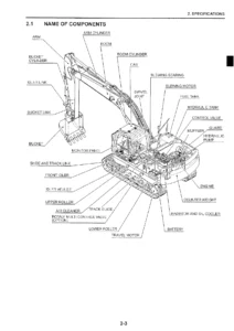
Doosan DX140LC Shop Manual K1027955AE-1 - Serial 5457 & Up Excavator Repair PDF β€” PDF page 1 preview
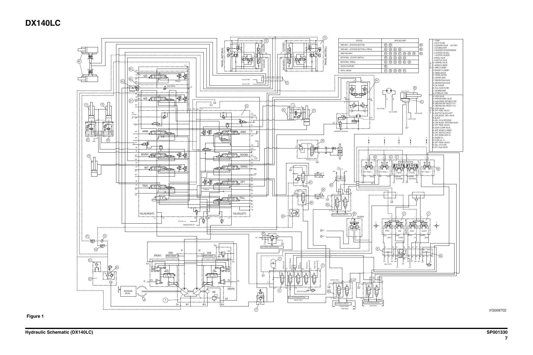
Doosan DX140LC Shop Manual K1027955AE-1 - Serial 5457 & Up Excavator Repair PDF β€” PDF page 639 preview
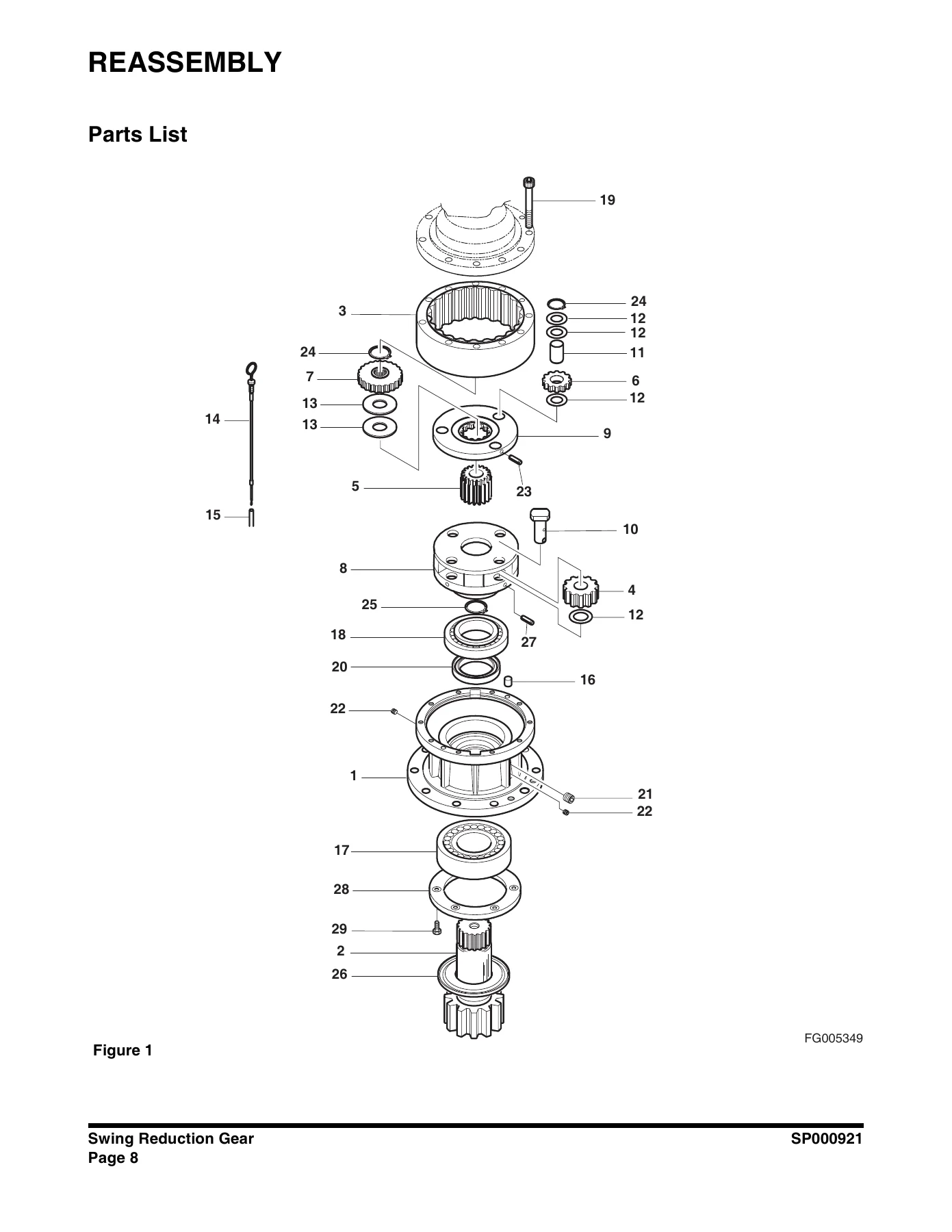
Doosan DX140LC Shop Manual K1027955AE-1 - Serial 5457 & Up Excavator Repair PDF β€” PDF page 200 preview

Instant PDF Delivery

This Doosan DX140LC Shop Manual is delivered as an instant PDF download after payment. There is no shipping, no waiting for a physical book, and no risk of a damaged or lost package. The file can be viewed on any deviceβ€”laptop, tablet, or smartphoneβ€”and printed pages can be taken directly to the machine when needed.

Whether you are performing a routine 500-hour service, diagnosing a hydraulic fault, overhauling a travel motor, or rebuilding a swing reduction gear, this manual gives you the complete, model-specific information to do the job correctly. It is the definitive reference for the DX140LC excavator, covering serial numbers 5457 and up.


Reviews

There are no reviews yet.

Be the first to review “Doosan DX140LC Shop Manual K1027955AE-1 – Serial 5457 & Up Excavator Repair PDF”

What Our Customers Say

β˜…β˜…β˜…β˜…β˜… Live reviews from customers
Loading customer reviews...
0
    0
    Your Cart
    Your cart is emptyReturn to Shop
    πŸ›’
    Recently Purchased
    πŸ•’ verified order