
Komatsu PC200-7 PC200LC-7 PC220-7 PC220LC-7 Shop Manual – PDF Workshop Manual
Original price was: $39.95.$23.95Current price is: $23.95.
Complete 810-page Komatsu shop manual for PC200-7, PC200LC-7, PC220-7 and PC220LC-7 hydraulic excavators, covering structure and function, testing and adjusting, disassembly and assembly, specifications and circuit diagrams.
Description
Komatsu PC200-7, PC200LC-7, PC220-7 and PC220LC-7 Shop Manual
This Komatsu PC200-7 PC200LC-7 PC220-7 PC220LC-7 Shop Manual is the full 810-page workshop reference for the four hydraulic excavators listed on the cover, covering serial numbers PC200-7 200001 and up, PC200LC-7 200001 and up, PC220-7 60001 and up and PC220LC-7 60001 and up. All four machines are powered by the SAA6D102E-2 engine, and the manual is split into the five service divisions Komatsu uses across its excavator range: General, Structure Function and Maintenance Standard, Testing and Adjusting, Disassembly and Assembly, and Others. Everything a technician needs to inspect, diagnose, adjust, remove, rebuild and reinstall the machine to specification is contained in this single document.
File Details
- Manual type: Shop manual (service and repair)
- Brand: Komatsu
- Models covered: PC200-7, PC200LC-7, PC220-7, PC220LC-7
- Engine: SAA6D102E-2
- Serial ranges: PC200-7 / PC200LC-7 from 200001; PC220-7 / PC220LC-7 from 60001
- Language: English
- Page count: 810 pages
- File format: PDF
- Document number: SEBM024312
Chapters Covered
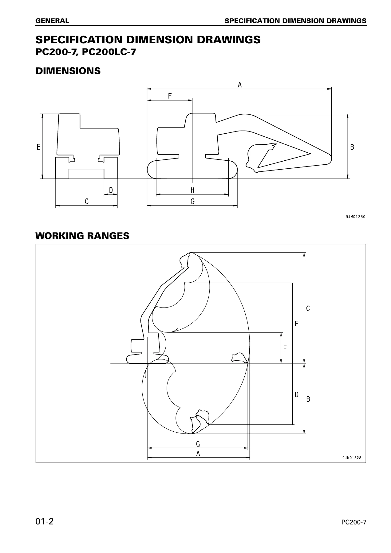
- 01 GENERAL – specification dimension drawings for PC200-7/PC200LC-7 and PC220-7/PC220LC-7; specifications; weight tables; fuel, coolant and lubricants
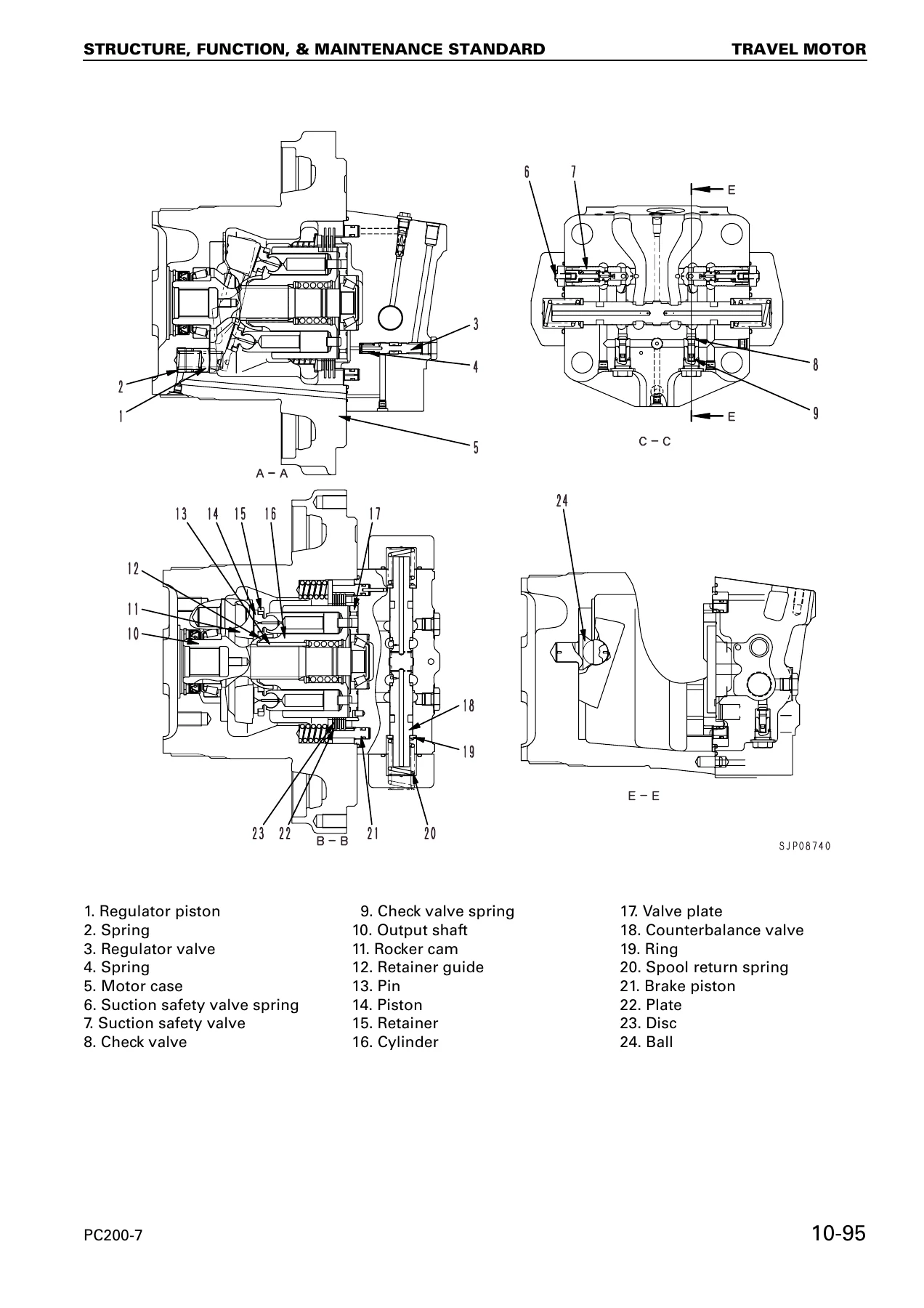
- 10 STRUCTURE, FUNCTION AND MAINTENANCE STANDARD – engine related parts; radiator, oil cooler and aftercooler; power train; final drive; swing machinery; swing circle; track frame and recoil spring; idler, carrier roller, track roller and track shoe; hydraulic equipment layout drawing; hydraulic tank and hydraulic pump; control valve; CLSS; self pressure reducing valve; swing motor and reverse prevention valve; center swivel joint, travel motor and travel junction valve; stroke regulation when travelling and valve control; work equipment, swing, travel and service PPC valves; solenoid valve, PPC accumulator and return oil filter; boom hydraulic drift prevention valve, lift check valve and attachment circuit selector valve; hydraulic cylinders; work equipment; air conditioner; engine control; electronic control system; multi monitor system, 7-segment monitor system and sensors
- 20 TESTING AND ADJUSTING – standard value table for engine related parts; standard value table for chassis related parts; testing and adjusting procedures; troubleshooting
- 30 DISASSEMBLY AND ASSEMBLY – starting motor; fuel injection pump; engine front and rear seals; cylinder head; radiator; hydraulic oil cooler; engine and hydraulic pump assemblies; final drive; swing motor and swing machinery; carrier roller, track roller, idler, recoil spring, sprocket, track shoe and swing circle; revolving frame; center swivel joint; hydraulic tank; control valve; hydraulic pump; input shaft oil seal; work equipment and travel PPC valves; hydraulic cylinders; work equipment; air conditioner unit; counterweight; operator’s cab; cab glass; front window; monitor; governor pump controller
- 90 OTHERS – hydraulic circuit diagrams and electrical circuit diagrams
Read together, these five divisions give a complete technical picture of the machine. The General chapter fixes the working envelope, weights and fluid requirements. The Structure, Function and Maintenance Standard chapter explains how each assembly is built and how it should behave, and it also carries the maintenance standards, wear limits and service limits used to judge whether a disassembled part can be reused. The Testing and Adjusting chapter supplies the measurement conditions, standard values and permissible values for the engine, hydraulics, swing and travel circuits, along with the adjustment points and torques needed to bring a machine back into tolerance. The Disassembly and Assembly chapter walks through removal, dismantling, inspection, reassembly and installation of the major components, including tightening torques, coating materials, special tools and air-bleeding requirements. The Others chapter gathers the hydraulic and electrical circuit diagrams that support diagnosis across the whole machine.
What a Technician Can Do With This Manual
The Komatsu PC200-7 PC200LC-7 PC220-7 PC220LC-7 Shop Manual supports the jobs that actually come through a service bay. Engine side, it covers engine speed checks, valve clearance adjustment, compression and blow-by pressure measurement, fuel injection timing, engine oil pressure and the adjustment of the engine speed sensor. Hydraulic side, it covers relief pressures for the work equipment, swing and travel circuits, control circuit pressure, PC and LS control circuit pressures, solenoid valve output pressure and PPC valve output pressure, along with the procedures for adjusting the main relief valve, swing relief pressure, PC valves and LS valves. The electronic control system is documented with the engine/pump composite control, pump/valve control, one-touch power maximizing, auto-deceleration, auto warm-up and overheat prevention, swing control, travel control and attachment flow control functions, plus the monitor panel service menus and the sensor and pressure switch data needed to trace faults.
For major repairs, the manual goes deep. The final drive is covered down to bearing, nut and floating seal fits with press-fitting forces and tangential force limits. Swing motor and swing machinery disassembly and assembly is documented with the special tools and the serial-number-based repair notes, including the change from grease-lubricated to oil-lubricated structure on early machines. Hydraulic cylinders are covered with piston ring expansion, head assembly press-fitting and the machining and caulking steps for reused rods and pistons. The control valve section covers pressure compensation valve seal replacement with guide tools, filter orientation and cover bolt tightening sequences. The travel PPC valve, work equipment PPC valve and center swivel joint each have their own assembly precautions and torque tables.
Correct procedures and correct specifications matter here because this is a load-sensing, closed-centre hydraulic machine with electronically controlled pump regulation. A relief pressure set too high stresses the pump and engine; set too low it costs digging force. Pump absorption torque adjustments change how much of the engine’s output the pump can use, and getting them wrong shows up as stall or sluggishness. Wear limits on the undercarriage and swing components decide whether a part goes back in or is replaced, and the manual gives the numbers to make that call. Torque values on the final drive, swing circle, track shoe and cylinder head are safety-critical, and the manual states them explicitly.
This is also a document that spans four machines in two size classes. The PC200-7 and PC200LC-7 are covered alongside the larger PC220-7 and PC220LC-7, with differences in dimensions, working ranges, weights, track components and some reduction ratios noted where they apply. The electrical and hydraulic circuit diagrams in the Others chapter are common reference material, and the connector tables, T-adapter part numbers and fuse box connection tables support actual hands-on fault finding rather than just background reading.
Delivery
IMAGES PREVIEW
The complete Komatsu PC200-7 PC200LC-7 PC220-7 PC220LC-7 Shop Manual is delivered as a downloadable PDF once payment is confirmed. There is no physical shipment and no waiting for a courier. The file can be opened on a workshop desktop, a laptop, a tablet or a phone, searched on screen while you work, and printed page by page if you prefer a paper copy at the machine. Because it is a single file, the whole manual travels with the technician, including the specification tables and circuit diagrams that are needed most often in the field.

Reviews
There are no reviews yet.