
Komatsu PC300-6, PC300LC-6, PC350-6, PC350LC-6 Shop Manual SEBM014302 – PDF Download
Original price was: $39.95.$23.95Current price is: $23.95.
Complete Komatsu shop manual for PC300-6, PC300LC-6, PC350-6 and PC350LC-6 excavators (SAA6D108-2 engine) under document number SEBM014302. 788 pages of specifications, structure and function, testing and adjusting, disassembly and assembly, maintenance standards and circuit diagrams, delivered as an instant PDF download.
Description
Komatsu PC300-6, PC300LC-6, PC350-6 and PC350LC-6 Shop Manual – SEBM014302
This is the full Komatsu shop manual for the PC300-6, PC300LC-6, PC350-6 and PC350LC-6 hydraulic excavators, issued under document number SEBM014302. It is the structured workshop reference rather than an operator booklet: general specifications, structure and function of every major assembly, testing and adjusting procedures with judgement values, complete disassembly and assembly sequences, maintenance standards for wear limits, and the hydraulic and electric circuit diagrams collected in the Others section. Everything is written for the serviceman who has to make a decision on the machine – what to measure, what the reading should be, what to take apart, and what to put back at which torque.
The Komatsu PC300-6 / PC300LC-6 / PC350-6 / PC350LC-6 Shop Manual SEBM014302 covers serial numbers 33001 and up for the PC300-6 and PC300LC-6, and 12001 and up for the PC350-6 and PC350LC-6. All four machines mount the SAA6D108-2 engine.
File Details
- Manual type: Shop Manual (Workshop / Service Manual)
- Brand: Komatsu
- Models covered: PC300-6, PC300LC-6, PC350-6, PC350LC-6
- Document number: SEBM014302
- Serial number coverage: PC300-6 and PC300LC-6 – 33001 and up; PC350-6 and PC350LC-6 – 12001 and up
- Engine: SAA6D108-2
- Language: English
- Format: PDF
- Page count: 788 pages
Chapters Covered
The manual is divided into six numbered sections, each of which is then broken down into the individual component groups of the machine.
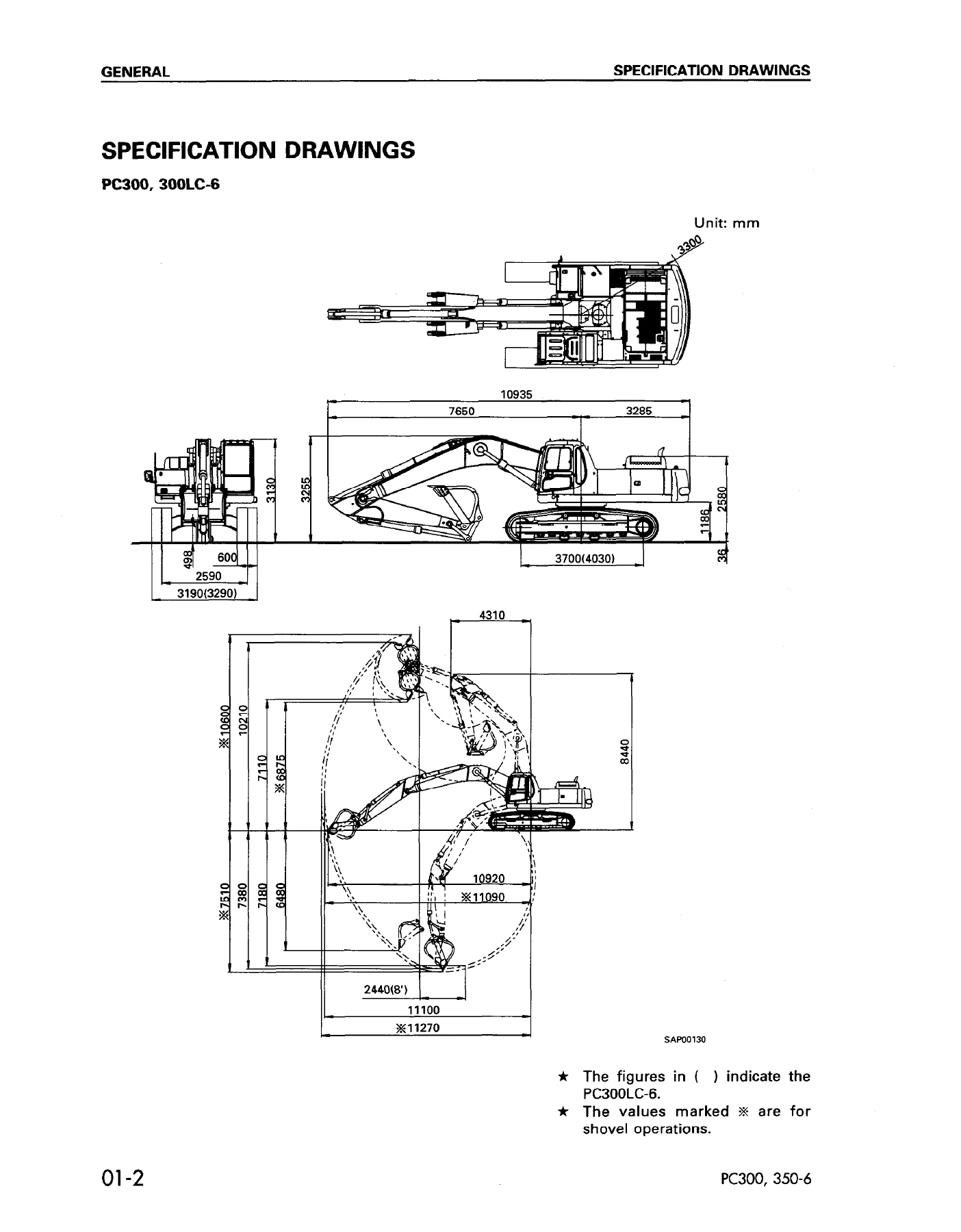
- 01 General – specification drawings, specifications, weight table, fuel, coolant and lubricants
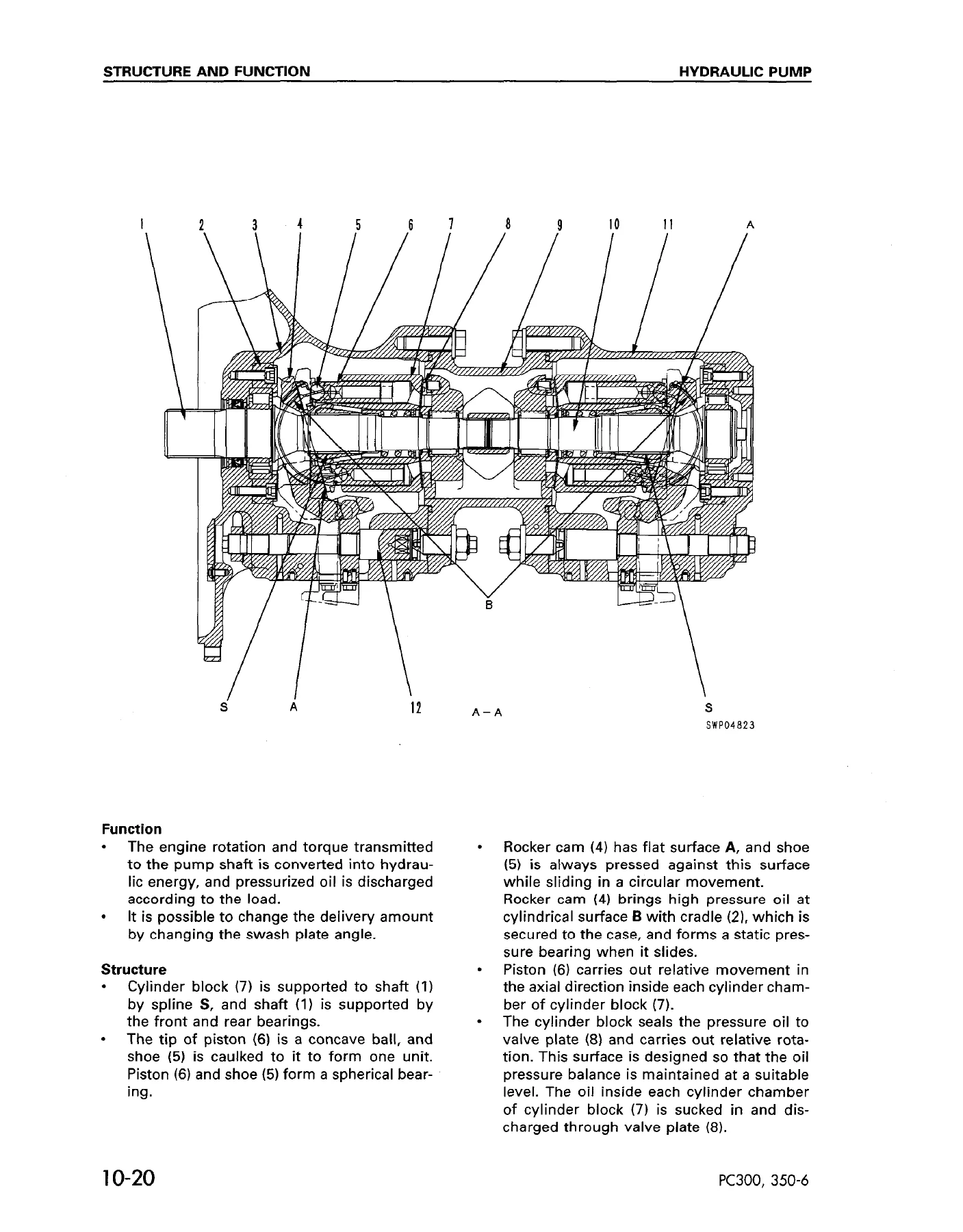
- 10 Structure and Function – parts related to engine, radiator and oil cooler, power train, final drive, swing circle, swing machinery, track frame and recoil spring, track shoe, hydraulic piping drawing, hydraulic circuit diagram, hydraulic tank and hydraulic filter, hydraulic pump, control valve, self-reducing pressure valve, suction safety valve, CLSS, swing motor, center swivel joint, travel motor, valve control, work equipment and swing PPC valve, travel PPC valve, service PPC valve, PPC safety lock valve, PPC accumulator, PPC shuttle valve and travel junction valve, LS-EPC valve, solenoid valve, boom holding valve, work equipment, air conditioner, actual electric wiring diagram, electric circuit diagram, engine control, electronic control system, machine monitor system, front window auto pull-up system
- 20 Testing and Adjusting – standard value tables for engine related parts, chassis related parts and electrical parts, tools for testing and adjusting, measuring engine speed, measuring exhaust colour, adjusting valve clearance, measuring compression pressure, measuring blow-by pressure, testing and adjusting fuel injection timing, measuring engine oil pressure, belt tension checks and adjustments, adjusting engine speed, measuring air supply (boost) pressure, testing and adjusting governor motor lever stroke, hydraulic pressure in work equipment/swing/travel circuit, TVC valve output pressure, LS valve output pressure and LS differential pressure, control circuit oil pressure, solenoid valve output pressure, PPC valve output pressure and PPC shuttle valve testing, adjusting work equipment and swing PPC valve, testing travel deviation, testing locations causing hydraulic drift, measuring oil leakage, releasing remaining pressure, testing swing circle bearing clearance, testing sprocket wear, track shoe tension, bleeding air, troubleshooting charts
- 30 Disassembly and Assembly – starting motor, alternator, engine oil cooler, fuel injection pump, water pump, nozzle holder, turbocharger, thermostat, engine front seal, engine rear seal, governor motor, cylinder head, aftercooler, hydraulic cooler, radiator and hydraulic cooler, engine and main pump, damper, fuel tank, center swivel joint, final drive, sprocket, swing motor, swing machinery, revolving frame, swing circle, idler and recoil spring, idler, recoil spring, track roller, carrier roller, track shoe, hydraulic tank, main pump, main pump input shaft oil seal, control valve, pump merge/divider valve, pressure compensation valve, servo valve for front and rear pump, LS-EPC solenoid valve, solenoid valve, work equipment PPC valve, travel PPC valve, PPC shuttle valve, boom lock valve, boom cylinder, arm cylinder, bucket cylinder, hydraulic cylinder, work equipment, bucket, arm, bucket and arm, boom, operator’s cab, counterweight, air conditioner compressor, condenser, receiver tank, air conditioner unit, governor and pump controller, monitor panel, control stand case
- 40 Maintenance Standard – engine mount, swing machinery, swing circle, final drive, track frame and recoil spring, idler, carrier roller, track roller, track shoe, hydraulic pump, control valve, self-reducing pressure valve, suction-safety valve, swing motor, travel motor, work equipment and swing PPC valve, travel PPC valve, service PPC valve, PPC shuttle valve and travel junction valve, LS-EPC valve, solenoid valve, center swivel joint, boom holding valve, hydraulic cylinder, work equipment, dimensions of work equipment
- 90 Others – hydraulic circuit diagram, electric circuit diagram
What this gives a technician is a single, internally consistent reference for the whole machine. The Structure and Function section explains how each circuit and assembly actually works – the CLSS closed centre load sensing system, the TVC and LS valves inside the pump, the pressure compensation valves, the merge/divider logic, the boom and arm regeneration circuits, the counterbalance and safety valves in the travel motor, the swing holding brake and reverse prevention valve. Testing and Adjusting then turns that understanding into numbers: relief pressures, LS differential pressure, servo piston input pressure, control circuit pressure, PPC output pressure, unload pressure, and the standard value tables that tell you whether a reading is acceptable or already at the service limit. Maintenance Standard finishes the loop with the wear limits, clearances, interferences and spring data needed to judge a part as reusable or scrap.
What the Disassembly and Assembly Section Covers
The removal and installation procedures are written component by component and include the lifting weights, the special tools required, the tightening torques and the places where gasket sealant, thread tightener or anti-friction compound must be applied. The engine side of the manual covers the starting motor, alternator, engine oil cooler, fuel injection pump, water pump, nozzle holders, turbocharger, thermostat, front and rear crankshaft seals, governor motor and cylinder head. The powertrain side covers the damper, final drive, sprocket, swing motor and swing machinery, revolving frame and swing circle. The undercarriage side covers the idler, recoil spring, track roller, carrier roller and track shoe assembly, including the press-fitting forces and the master pin protrusion dimension. The hydraulic side covers the main pump, its input shaft oil seal, the control valve, the pump merge/divider valve, the pressure compensation valve, the servo valves, the LS-EPC solenoid valve, the solenoid valve block, all three PPC valves, the PPC shuttle valve, the boom lock valve and the hydraulic cylinders.
The hydraulic cylinder chapter is worth calling out on its own. It covers piston rod disassembly, the piston assembly, the cylinder head assembly with its dust seal, rod packing, buffer ring and bushing, and then the full assembly sequence – press fitting the bushing, expanding the piston ring, compressing it, installing the wear ring and ring, fitting the head assembly and torquing the mounting bolts to the value specific to the bucket, arm or boom cylinder. It also distinguishes between reusing an existing rod and piston assembly and fitting a new one, including when a new screw hole has to be machined and how the thread is to be caulked.
Hydraulic and Electrical Diagrams
The manual includes the hydraulic piping drawing, the hydraulic circuit diagram, the actual electric wiring diagram and the electric circuit diagram, plus the connector arrangement and connector pin number tables used for electrical troubleshooting. The control valve is documented both as a complete assembly and as a circuit, with port designations for every spool and the logic of the merge/divider valve, the LS select valve and the two-stage safety valve spelled out. For anyone chasing an electrical fault on these machines, the engine control, electronic control system and machine monitor system chapters describe the governor and pump controller, the input and output signals on each connector, the monitoring codes and the service code tables.
Engine Coverage Note
The PC300-6 and PC350-6 mount the SAA6D108-2 engine. This shop manual covers the engine-related parts as they are installed in the machine – removal and installation of the injection pump, water pump, nozzle holders, turbocharger, thermostat, cylinder head and the associated testing and adjusting values – and refers to the 108-2 Series Engine Shop Manual for the internal details of the engine itself.
Why This Manual Matters
These are load-sensing machines. The pump output is not fixed; it is controlled continuously by the TVC and LS valves in response to what the control valve is asking for. A machine that feels slow, that stalls the engine under load, that drifts, that will not travel straight, or that swings with excessive overrun can be caused by a dozen different things – a clogged throttle in the servo, a weak spool return spring, a leaking slipper seal in a pressure compensation valve, a sticking LS shuttle, a misadjusted TVC screw. Guessing at that is expensive. This manual gives you the measurement sequence, the expected value and the flow chart that narrows the fault down to the actual component, then gives you the disassembly and assembly procedure and the torque to put it right.
The Maintenance Standard section is equally important for anyone doing a rebuild or assessing a used machine. It lists the repair limits for idler tread and flange diameters, shaft and bushing clearances, link pitch, link height and bushing metal thickness, the sprocket tooth wear limit, the swing circle bearing clearance, the final drive backlash figures, and the spring free lengths, installed lengths and installed loads for the control valve, PPC valves, solenoid valves, swing motor, travel motor and boom holding valve. That is the difference between replacing a part because it looks worn and replacing it because it has actually passed its limit.
Instant PDF Delivery
The Komatsu PC300-6, PC300LC-6, PC350-6 and PC350LC-6 Shop Manual SEBM014302 is supplied as a PDF download. There is nothing to ship and nothing to wait for – the file is available immediately after payment. It opens on a workshop laptop, a tablet or a phone, individual pages or whole sections can be printed for use at the machine, and the pages can be kept on a USB stick in the service truck alongside your other reference material. Whether you are servicing one machine in a small fleet or running a repair shop that sees these excavators regularly, having the full manual on hand means you stop working from memory and start working from the numbers.


Reviews
There are no reviews yet.