★ TRUSTED BY 321,897+ PROFESSIONALS WORLDWIDE
🏒
Trusted Business
Verified & Licensed
πŸ›‘οΈ
Virus Free Files
100% Safe Downloads
πŸ”’
Secure Payment
SSL Protected
⚑
Instant Delivery
Available Immediately
Sale!

Komatsu PC800 PC800LC PC800SE PC850 PC850SE-8R1 Shop Manual SEN05279-00

Original price was: $49.95.Current price is: $29.95.

A 1,294-page Komatsu hydraulic excavator shop manual for PC800-8R1, PC800LC-8R1, PC800SE-8R1, PC850-8R1 and PC850SE-8R1 machines from serial number 70001 and up. Covers specifications, structure and function, standard values, testing and adjusting, troubleshooting, disassembly and assembly, maintenance standards, air conditioning, and hydraulic/electrical diagrams.

⚑
Instant PDF Download
Available immediately
πŸ’Ύ
Save to Your Device
Download & keep forever
πŸ›‘οΈ
Antivirus Scanned
100% virus-free
🌍
Trusted Worldwide
175,000+ customers

Description

Komatsu PC800 PC800LC PC800SE PC850 PC850SE-8R1 Shop Manual SEN05279-00

The Komatsu PC800 PC800LC PC800SE PC850 PC850SE-8R1 Shop Manual SEN05279-00 is a detailed workshop reference for the PC800-8R1, PC800LC-8R1, PC800SE-8R1, PC850-8R1 and PC850SE-8R1 hydraulic excavators from serial number 70001 and up. It brings together machine specifications, system construction and function, standard values, testing and adjustment procedures, troubleshooting, disassembly and assembly, maintenance standards, air-conditioner service information, and hydraulic and electrical circuit diagrams. The manual is organized for workshop service work, with procedures and reference data arranged by system so technicians can move from diagnosis to measurement, repair and final checks using the values and methods shown in the document.

File Details

  • Manual type: Shop Manual
  • Brand: Komatsu
  • Models: PC800-8R1, PC800LC-8R1, PC800SE-8R1, PC850-8R1, PC850SE-8R1
  • Serial coverage: 70001 and up for each listed model
  • Document number: SEN05279-00
  • Language: English
  • Pages: 1,294
  • File format: PDF

Workshop Information for the PC800 and PC850-8R1 Series

This manual goes well beyond basic maintenance. Its specification section identifies dimensional, performance, weight, fluid and lubricant information for the covered excavators, including the standard backhoe configurations and a PC800-8R1 loading shovel specification. The engine identified in the machine specifications is the Komatsu SAA6D140E-5, a six-cylinder engine, and the manual also provides machine-side engine testing, control, removal and installation information. For engine-part information, the manual itself directs the reader to the shop manual for the same engine model, an important distinction for anyone planning deep internal engine work.

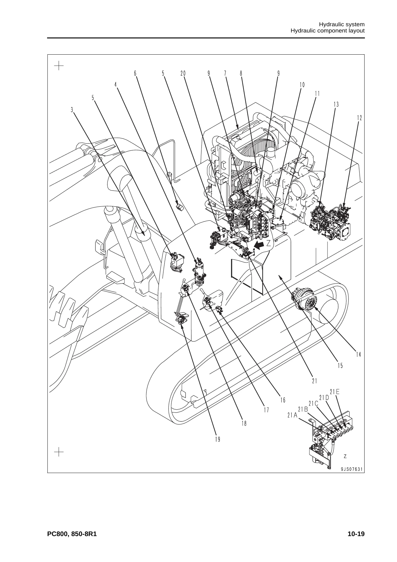
The hydraulic coverage is extensive. System chapters explain component layout, the hydraulic tank and filters, the HPV375+375 main hydraulic pump, pump control system, servo valve, self-pressure reducing valve, LPV90 cooling fan pump, LMF110 cooling fan motor, control valves, straight-travel valve, swing and travel motors, PPC valves, solenoid valves, accumulator, quick return valve and filtration circuits. Detailed drawings show component construction and oil-flow relationships, while testing sections provide procedures for checking work-equipment, swing, travel and control circuit pressures, main-pump control signals, PPC valve output pressure, fan circuit pressure, oil leakage and hydraulic drift.

Electrical and electronic systems receive their own structured treatment. The manual explains electric equipment handling, connector and wiring precautions, wire codes, engine control, machine electric control, the monitor system, sensors and KOMTRAX. Troubleshooting material includes connector layouts, connector pin tables, fuse locations and failure-code diagnostics. It also separates symptom diagnosis into electrical E-mode, hydraulic and mechanical H-mode, and engine S-mode sections, allowing the technician to follow the type of failure being investigated rather than relying on a single generic troubleshooting chart.

Testing, Diagnosis and Adjustment

The Komatsu PC800 PC800LC PC800SE PC850 PC850SE-8R1 Shop Manual SEN05279-00 is especially useful when a repair requires measured confirmation rather than guesswork. The standard value tables provide reference values for the engine and machine, while the testing and adjusting chapter explains the tools and procedures used to obtain the measurements. Engine-related checks include engine speed, boost pressure, exhaust gas temperature and color, valve clearance, compression pressure, blowby pressure, engine oil pressure, fuel pressure, fuel return rate and leakage, fuel-circuit bleeding and leakage checks, plus belt tension procedures.

Machine testing reaches into the undercarriage, hydraulic and electrical systems. Procedures cover swing-circle bearing clearance, track tension, work-equipment and travel circuit pressures, pump control, PPC pressures, travel deviation, hydraulic drift, fan speed and fan circuit pressure. The electrical section includes machine-monitor functions, controller voltage-circuit handling and preparation for electrical troubleshooting. A PM Clinic section and undercarriage inspection report provide additional structured service references.

Disassembly, Installation and Component Repair

For major mechanical work, the disassembly and assembly chapter lays out safe removal, installation, disassembly and reassembly procedures together with special-tool information and coating materials. Coverage includes the engine, PTO and hydraulic pump assembly, cooling assembly, aftercooler, fuel cooler and condenser, fan motor and fuel tank. Engine-related procedures include the fuel supply pump, cylinder head, injectors, and front and rear seals.

IMAGES PREVIEW

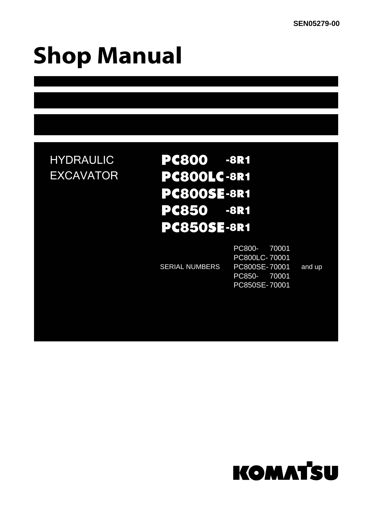
Komatsu PC800 PC800LC PC800SE PC850 PC850SE-8R1 Shop Manual SEN05279-00 β€” PDF page 1 preview
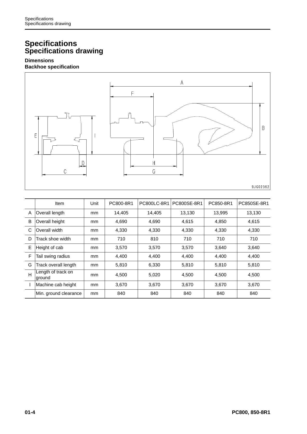
Komatsu PC800 PC800LC PC800SE PC850 PC850SE-8R1 Shop Manual SEN05279-00 β€” PDF page 68 preview
Komatsu PC800 PC800LC PC800SE PC850 PC850SE-8R1 Shop Manual SEN05279-00 β€” PDF page 115 preview

Power-train and undercarriage procedures include PTO work, swing motor and swing machinery, swing circle, final drive, track shoe separation and connection, field link work, idler, idler adjustment cylinder, recoil spring, carrier and track rollers, revolving frame and counterweight. Hydraulic repair procedures cover the hydraulic tank, main pump, fan pump, control valve, swing motor, center swivel joint, travel motor, solenoid valve, boom damping valve, work-equipment and travel PPC valves, hydraulic cylinders and grease gun. Work-equipment procedures include bucket, arm and boom cylinders as well as bucket, arm, boom and complete work-equipment assemblies. The cab and electrical sections include cab and glass removal, air-conditioner unit, engine controller, monitor, pump controller and KOMTRAX terminal.

Safety and preparation are integrated throughout the manual. The foreword emphasizes correct servicing methods, safe support and lifting practices, pressure release before disconnecting circuits, care with hydraulic contamination, connector handling, specified tightening torque, replacement of seals and locking parts, and correct bleeding and refilling after hydraulic work. Special-tool lists and component weights support planning before heavy assemblies are removed or handled.

Specifications, Service Limits and Maintenance Standards

The specification pages provide model-by-model working ranges, dimensions, machine weights, bucket capacities, digging performance, travel and swing data, ground pressure and engine information. Separate tables cover component weights and fuel, coolant and lubricant information. Refilling information includes the engine oil pan, coupling case, swing machinery, final drives, hydraulic system, fuel tank and cooling system, helping the technician identify the correct service reference before work begins.

The maintenance-standard chapter then supplies wear and service criteria for key assemblies. It covers the coupling, swing circle, swing machinery, final drive, sprocket, track frame and idler cushion, idler, carrier roller, track roller, track shoe, cooling fan motor, control valve, swing motor, center swivel joint, PPC valve, work equipment and hydraulic cylinders. The manual explains how standard dimensions, tolerances, clearances, repair limits and allowable values are used to judge whether components remain serviceable or require repair or replacement.

Chapters Covered

  • 00 Index and foreword
    • Safety and general information; how to read the shop manual
    • Maintenance-standard terminology; fuel, intake and hydraulic component handling
    • Push-pull couplers; electric equipment and electric wire codes
    • KOMTRAX use; work precautions; tightening torque, abbreviations and conversion tables
  • 01 Specification
    • Specification drawings, dimensions and working ranges
    • Model specifications and performance data
    • Component weight tables
    • Fuel, coolant, lubricant and refill information
  • 10 Structure and function
    • Engine and cooling system, coupling and coupling lubrication
    • Power train, swing circle, swing machinery and final drive
    • Undercarriage, track frame and idler cushion
    • Hydraulic component layout, tank, pumps, pump control and servo systems
    • Control valves, swing and travel motors, PPC and solenoid valves, accumulator and filters
    • Engine control, electric control, monitor, sensors and KOMTRAX
  • 20 Standard value table
    • Engine standard values
    • Machine standard values for testing, adjustment and troubleshooting
  • 30 Testing and adjusting
    • Tools for testing, adjusting and troubleshooting
    • Engine speed, boost, exhaust, compression, blowby, oil and fuel checks
    • Swing-circle clearance and track tension
    • Hydraulic pressures, pump control, PPC output, travel deviation and hydraulic drift
    • Fan tests, leakage checks, pressure release and air bleeding
    • Electrical preparation, monitor functions and PM Clinic inspection
  • 40 Troubleshooting
    • Troubleshooting principles, failure-code tables and symptom indexes
    • Connector layouts, pin tables, branch adapters and fuse locations
    • Failure-code diagnosis for engine, machine control and electrical circuits
    • E-mode electrical troubleshooting
    • H-mode hydraulic and mechanical troubleshooting
    • S-mode engine troubleshooting
  • 50 Disassembly and assembly
    • General procedures, coating materials and special tools
    • Engine, cooling system, PTO and fuel-system component procedures
    • Swing machinery, swing circle and final drive procedures
    • Track, idler, recoil spring, rollers, frame and counterweight procedures
    • Hydraulic pump, valve, motor, swivel joint, PPC valve and cylinder procedures
    • Work equipment, cab, air conditioner, controllers, monitor and KOMTRAX terminal

    Complete PDF Bookmark Tree

    Complete Bookmarks

    The complete bookmarks in the β€œKomatsu PC800 PC800LC PC800SE PC850 PC850SE-8R1 Shop Manual SEN05279-00” are as follows:

    COBERp. 1
    00 Index and forewordp. 3
    Table of contentsp. 4
    Foreword and general information Important safety noticep. 14
    How to read the shop manualp. 21
    Explanation of terms for maintenance standardp. 23
    Handling equipment of fuel system devicesp. 25
    Handling of intake system partsp. 26
    Handling of hydraulic componentsp. 27
    Method of disconnecting and connecting push-pull type couplerp. 29
    Handling of electric equipmentp. 32
    How to read electric wire codep. 41
    Practical use of KOMTRAXp. 47
    Precautions when performing workp. 48
    Standard tightening torque tablep. 51
    List of abbreviationp. 55
    Conversion tablep. 60
    01 Specificationp. 65
    Contentsp. 66
    Specificationsp. 68
    Specifications drawingp. 68
    Specificationsp. 72
    Table of weightp. 84
    Table of fuel, coolant and lubricantsp. 94
    10 Structure and functionp. 97
    Contentsp. 98
    Engine and cooling systemp. 99
    Couplingp. 99
    Coupling lubrication systemp. 100
    Cooling systemp. 102
    Power train systemp. 104
    Power trainp. 104
    Swing circlep. 106
    Swing machineryp. 107
    Final drivep. 109
    Undercarriage and framep. 110
    Track framep. 110
    Idler cushionp. 112
    Hydraulic systemp. 114
    Hydraulic component layoutp. 114
    Hydraulic tank and filterp. 116
    Hydraulic pumpp. 118
    Pump control systemp. 126
    Servo valvep. 128
    Self-pressure reducing valvep. 137
    Cooling fan pumpp. 140
    Cooling fan motorp. 149
    Electrical grease pumpp. 155
    Control valvep. 156
    Straight-travel valvep. 165
    Swing motorp. 168
    Center swivel jointp. 172
    Travel motorp. 173
    PPC valvep. 183
    Solenoid valvep. 191
    Accumulatorp. 199
    Quick return valvep. 200
    Line oil filterp. 204
    Pilot oil filterp. 205
    Drain oil filterp. 206
    Electrical systemp. 207
    Engine controlp. 207
    Electric control systemp. 215
    Monitor systemp. 254
    Sensorsp. 284
    KOMTRAX systemp. 288
    20 Standard value tablep. 291
    Contentsp. 292
    Standard value tablep. 293
    Standard value table for enginep. 293
    Standard value table for machinep. 294
    30 Testing and adjustingp. 307
    Contentsp. 308
    Tool for testing, adjusting and troubleshootingp. 309
    Tools for testing, adjusting, and troubleshootingp. 309
    Engine and cooling systemp. 313
    Testing engine speedp. 313
    Testing intake air pressure (Boost pressure)p. 314
    Testing exhaust gas temperaturep. 315
    Testing exhaust gas colorp. 316
    Adjusting valve clearancep. 318
    Testing compression pressurep. 319
    Testing blowby pressurep. 321
    Handling fuel system partsp. 323
    Releasing remaining pressure from fuel systemp. 324
    Testing fuel pressurep. 325
    Testing fuel return rate and leakagep. 326
    Bleeding air from fuel circuitp. 329
    Testing fuel circuit for leakagep. 331
    Testing and adjusting alternator belt tensionp. 332
    Testing and adjusting air conditioner compressor belt tensionp. 333
    Undercarriage and framep. 334
    Testing swing circle bearing clearancep. 334
    Testing and adjusting track tensionp. 335
    Hydraulic systemp. 336
    Testing and adjusting oil pressure in work equipment, swing, and travel circuitsp. 336
    Testing and adjusting control circuit oil pressure (output pressure of self-pressure reducing valve)p. 342
    Testing and adjusting control signal of main pumpp. 344
    Testing PPC valve output pressurep. 351
    Testing outlet pressure of solenoid valve, swing PPC shuttle valve, and swing priority selector valvep. 356
    Adjusting play of work equipment and swing PPC valvesp. 361
    Testing and adjusting travel deviationp. 362
    Inspecting locations of hydraulic drift in work equipmentp. 364
    Testing fan speedp. 365
    Testing fan circuit oil pressurep. 366
    Testing fan pump EPC currentp. 367
    Testing fan pump EPC solenoid valve outlet pressurep. 368
    Testing oil leakagep. 369
    Releasing remaining pressure from hydraulic circuitp. 373
    Bleeding air from various partsp. 374
    Inspection procedures for diodep. 377
    Adjusting mirrorsp. 378
    Electrical systemp. 379
    Special functions of machine monitorp. 379
    Handling voltage circuit of engine controllerp. 423
    Preparatory work for troubleshooting of electrical systemp. 424
    Pm Clinicp. 428
    Pm clinic servicep. 428
    UNDERCARRIAGE INSPECTION REPORTp. 435
    40 Troubleshootingp. 437
    Contentsp. 438
    General information on troubleshootingp. 443
    Points to remember when troubleshootingp. 443
    Sequence of events in troubleshootingp. 444
    Checks before troubleshootingp. 445
    Classification and procedures for troubleshootingp. 471
    Failure codes tablep. 474
    Symptom and troubleshooting numbersp. 479
    Information in troubleshooting tablep. 482
    Troubleshooting method for open circuit in wiring harness of pressure sensor systemp. 484
    Connector list and layoutp. 486
    Connection table for connector pin numbersp. 497
    T- branch box and T- branch adapter tablep. 533
    Fuse locationsp. 536
    Troubleshooting by failure codep. 539
    Failure code [989L00] Engine Controller Lock Caution 1p. 539
    Failure code [989M00] Engine Controller Lock Caution 2p. 540
    Failure code [989N00] Engine Controller Lock Caution 3p. 540
    Failure code [AA10NX] Air Cleaner Cloggingp. 541
    Failure code [AB00KE] Charge Voltage Lowp. 542
    Failure code [B@BAZG] Eng Oil Press Lowp. 544
    Failure code [B@BAZK] Eng Oil Level Lowp. 545
    Failure code [B@BCNS] Eng Water Overheatp. 546
    Failure code [B@BCZK] Eng Water Level Lowp. 548
    Failure code [B@HANS] Hyd Oil Overheatp. 550
    Failure code [CA111] ECM Critical Internal Failurep. 552
    Failure code [CA115] Eng Ne and Bkup Speed Sens Errorp. 554
    Failure code [CA122] Chg Air Press Sensor High Errorp. 556
    Failure code [CA123] Chg Air Press Sensor Low Errorp. 558
    Failure code [CA131] Throttle Sensor High Errorp. 560
    Failure code [CA132] Throttle Sensor Low Errorp. 562
    Failure code [CA135] Eng Oil Press Sensor High Errorp. 564
    Failure code [CA141] Eng Oil Press Sensor Low Errorp. 566
    Failure code [CA144] Coolant Temp Sens High Errorp. 568
    Failure code [CA145] Coolant Temp Sens Low Errorp. 570
    Failure code [CA153] Chg Air Temp Sensor High Errorp. 572
    Failure code [CA154] Chg Air Temp Sensor Low Errorp. 574
    Failure code [CA187] Sens Supply 2 Volt Low Errorp. 576
    Failure code [CA221] Ambient Press Sens High Errorp. 578
    Failure code [CA222] Ambient Press Sens Low Errorp. 580
    Failure code [CA227] Sens Supply 2 Volt High Errorp. 582
    Failure code [CA238] Ne Speed Sens Supply Volt Errorp. 584
    Failure code [CA263] Fuel Temp Sensor High Errorp. 586
    Failure code [CA265] Fuel Temp Sensor Low Errorp. 588
    Failure code [CA271] IMV/PCV1 Short Errorp. 590
    Failure code [CA272] IMV/PCV1 Open Errorp. 591
    Failure code [CA273] PCV2 Short Errorp. 592
    Failure code [CA274] PCV2 Open Errorp. 593
    Failure code [CA322] Inj #1(L#1) Open/Short Errorp. 594
    Failure code [CA323] Inj #5 (L#5) Open/Short Errorp. 596
    Failure code [CA325] Inj #6 (L#6) Open/Short Errorp. 600
    Failure code [CA331] Inj #2(L#2) Open/Short Errorp. 602
    Failure code [CA332] Inj #4 (L#4) Open/Short Errorp. 604
    Failure code [CA342] Calibration Code Incompatibilityp. 606
    Failure code [CA351] Injectors Drive Circuit Errorp. 607
    Failure code [CA352] Sens Supply 1 Volt Low Errorp. 608
    Failure code [CA386] Sens Supply 1 Volt High Errorp. 610
    Failure code [CA441] Battery Voltage Low Errorp. 610
    Failure code [CA442] Battery Voltage High Errorp. 611
    Failure code [CA449] Rail Press Very High Errorp. 611
    Failure code [CA451] Rail Press Sensor High Errorp. 612
    Failure code [CA452] Rail Press Sensor Low Errorp. 614
    Failure code [CA553] Rail Press High Errorp. 616
    Failure code [CA554] Rail Press Sensor In Range Errorp. 617
    Failure code [CA559] Supply Pump Press Low Error 1p. 618
    Failure code [CA689] Eng Ne Speed Sensor Errorp. 622
    Failure code [CA731] Eng Bkup Speed Sens Phase Errorp. 624
    Failure code [CA757] All Continuous Data Lost Errorp. 625
    Failure code [CA778] Eng Bkup Speed Sensor Errorp. 626
    Failure code [CA1633] KOMNET Datalink Timeout Errorp. 628
    Failure code [CA2185] Throt Sens Sup Volt High Errorp. 630
    Failure code [CA2186] Throt Sens Sup Volt Low Errorp. 632
    Failure code [CA2249] Rail Press Very Low Errorp. 633
    Failure code [CA2555] Grid Htr Relay Open Circuit Errorp. 634
    Failure code [CA2556] Grid Htr Relay Short Circuit Errorp. 636
    Failure code [D110KB] Battery Relay Drive Short Circuitp. 638
    Failure code [D163KB] Flash Light Relay Short Circuitp. 640
    Failure code [D195KA] Step Light Relay Open Circuitp. 642
    Failure code [D195KB] Step Light Relay Short Circuitp. 644
    Failure code [D19JKZ] Personal Code Relay Abnormalityp. 646
    Failure code [D862KA] GPS Antenna Open Circuitp. 648
    Failure code [DA22KK] Pump Solenoid Power Low Errorp. 650
    Failure code [DA25KP] 5V Sensor1 Power Abnormalityp. 652
    Failure code [DA29KQ] Model Selection Abnormalityp. 654
    Failure code [DA2RMC] CAN Discon (Pump Con Detected)p. 656
    Failure code [DA80MA] Auto. Lub. Abnormal.p. 660
    Failure code [DAF8KB] Camera Power Supply Short Circuitp. 662
    Failure code [DAFGMC] GPS Module Errorp. 664
    Failure code [DAFRMC] CAN Discon (Monitor Detected)p. 665
    Failure code [DGE5KB] Ambi. Temp Sensor Short Circuitp. 670
    Failure code [DGH2KB] Hyd Oil Sensor Shortp. 672
    Failure code [DH25KA] L Jet Sensor Open Circuitp. 674
    Failure code [DH25KB] L Jet Sensor Short Circuitp. 676
    Failure code [DH26KA] R Jet Sensor Open Circuitp. 678
    Failure code [DH26KB] R Jet Sensor Short Circuitp. 680
    Failure code [DHPEKA] F Pump P. Sensor Open Circuitp. 682
    Failure code [DHPEKB] F Pump P. Sensor Short Circuitp. 684
    Failure code [DHPFKA] R Pump P. Sensor Open Circuitp. 686
    Failure code [DHPFKB] R Pump P. Sensor Short Circuitp. 688
    Failure code [DV20KB] Travel alarm short circuitp. 690
    Failure code [DW41KA] Swing Priority Sol Open Circuitp. 692
    Failure code [DW41KB] Swing Priority Sol Short Circuitp. 694
    Failure code [DW43KA] Travel Speed Sol Open Circuitp. 696
    Failure code [DW43KB] Travel Speed Sol Short Circuitp. 698
    Failure code [DW45KA] Swing Brake Sol Open Circuitp. 700
    Failure code [DW45KB] Swing Brake Sol Short Circuitp. 702
    Failure code [DW7BKA] Fan Reverse Sol Open Circuitp. 704
    Failure code [DW7BKB] Fan Reverse Sol Short Circuitp. 706
    Failure code [DW7JKA] Bottom Dump Priority Sol Open Circuitp. 708
    Failure code [DW7JKB] Bottom Dump Priority Sol Short Circuitp. 710
    Failure code [DW91KA] Travel Junction Sol Open Circuitp. 712
    Failure code [DW91KB] Travel Junction Sol Short Circuitp. 714
    Failure code [DWK0KA] 2-stage Relief Sol Open Circuitp. 716
    Failure code [DWK0KB] 2-stage Relief Sol Short Circuitp. 718
    Failure code [DX16KA] Fan Pump EPC Sol Open Circuitp. 720
    Failure code [DX16KB] Fan Pump EPC Sol Short Circuitp. 722
    Failure code [DXAAKA] F Pump EPC Sol Open Circuitp. 724
    Failure code [DXAAKB] F Pump EPC Sol Short Circuitp. 726
    Failure code [DXABKA] R Pump EPC Sol Open Circuitp. 728
    Failure code [DXABKB] R Pump EPC Sol Short Circuitp. 730
    Failure code [DY20KA] Wiper Working Abnormalityp. 732
    Failure code [DY20MA] Wiper Parking Abnormalityp. 736
    Failure code [DY2CKA] Washer Drive Open Circuitp. 738
    Failure code [DY2CKB] Washer Drive Short Circuitp. 740
    Failure code [DY2DKB] Wiper Drive (Fwd) Short Circuitp. 742
    Failure code [DY2EKB] Wiper Drive (Rev) Short Circuitp. 746
    Failure code [DY2FMA] Upper Wiper Working Abnormalityp. 750
    Failure code [DY2GKM] Wiper Select Abnormalityp. 752
    Troubleshooting of electrical system (E-mode)p. 755
    E-1 Engine does not start (Engine does not crank)p. 755
    E-2 Preheater does not operatep. 760
    E-3 When starting switch is turned to ON position, machine monitor displays nothingp. 764
    E-4 When starting switch is turned to ON position (before starting engine), basic check monitor lights up.p. 767
    E-5 Precaution item lights up while engine is runningp. 768
    E-6 Emergency stop item lights up while engine is runningp. 770
    E-7 Engine coolant temperature gauge does not indicate properlyp. 771
    E-8 Fuel gauge does not indicate properlyp. 772
    E-9 Hydraulic oil temperature gauge does not indicate properlyp. 774
    E-10 Displays on machine monitor are different from those for actual machinep. 776
    E-11 Some areas of machine monitor screen are not displayedp. 776
    E-12 Function switch does not operatep. 776
    E-13 Automatic warm-up system does not operate (in cold season)p. 777
    E-14 Auto-decelerator does not operate properlyp. 778
    E-15 Working mode does not changep. 779
    E-16 Travel speed does not changep. 780
    E-17 Alarm buzzer cannot be canceledp. 781
    E-18 When starting switch is turned OFF, service meter is not displayed40p. 781
    E-19 Service mode cannot be selectedp. 781
    E-20 Any of work equipment, swing and travel do not operate or cannot be lockedp. 782
    E-21 Machine push-up function does not operate or cannot be canceled40p. 784
    E-22 Boom shockless function does not operate properlyp. 786
    E-23 Swing brake does not operate properlyp. 788
    E-24 Windshield wiper and window washer do not operatep. 790
    E-25 Travel alarm does not sound or does not stop soundingp. 794
    E-26 Boom RAISE indicator is not displayed properly with monitoring functionp. 796
    E-27 Boom LOWER indicator is not displayed properly with monitoring functionp. 798
    E-28 Arm IN indicator is not displayed properly with monitoring function40p. 800
    E-29 Arm OUT indicator is not displayed properly with monitoring functionp. 802
    E-30 Bucket CURL indicator is not displayed properly with monitoring functionp. 804
    E-31 Bucket DUMP indicator is not displayed properly with monitoring functionp. 806
    E-32 Swing indicator is not displayed properly with monitoring functionp. 808
    E-33 "L.H. travel" is not displayed properly with monitoring functionp. 810
    E-34 "R.H. travel" is not displayed properly with monitoring functionp. 812
    E-35 "Attachment" is not displayed properly with monitoring functionp. 814
    E-36 Electric grease gun does not operatep. 816
    E-37 KOMTRAX system does not operate properlyp. 818
    E-38 Horn does not sound or does not stop soundingp. 819
    E-39 Step light does not light up or go offp. 822
    Troubleshooting of hydraulic and mechanical system (H-mode)p. 826
    Before starting troubleshooting for hydraulic and mechanical systemsp. 826
    Information in troubleshooting table (H-mode)p. 830
    H-1 All of work equipment, swing and travel work slow or lack powerp. 832
    H-2 Engine speed lowers significantly or engine stallsp. 834
    H-3 Any of work equipment, swing and travel does not workp. 836
    H-4 Unusual noise is heard from around hydraulic pumpp. 838
    H-5 Boom operation lacks speed or powerp. 839
    H-6 Arm operation lacks speed or powerp. 841
    H-7 Bucket operation lacks speed or powerp. 842
    H-8 Boom does not movep. 843
    H-9 Arm does not movep. 843
    H-10 Bucket does not movep. 843
    H-11 Hydraulic drift of work equipment is largep. 844
    H-12 Time lag of work equipment is largep. 846
    H-13 Heavy lift function does not work or is not releasedp. 847
    H-14 Machine push-up function does not work or is not releasedp. 847
    H-15 Boom shockless function does not work or is not canceledp. 847
    H-16 Machine deviates in one direction against operator's intention when travellingp. 848
    H-17 Machine deviates significantly at startp. 851
    H-18 Machine deviates significantly during combined operationp. 852
    H-19 Travel works slow or lack powerp. 853
    H-20 One of tracks does not runp. 854
    H-21 Travel speed does not changep. 855
    H-22 Upper structure does not swingp. 856
    H-23 Swing speed is low or swing acceleration is poorp. 857
    H-24 In combined operation with work equipment, swing speed is low or swing acceleration is poorp. 858
    H-25 Upper structure overruns excessively when it stops swingingp. 860
    H-26 Shock is large when upper structure stops swingingp. 861
    H-27 Large unusual noise is heard when upper structure stops swinging40p. 862
    H-28 Swing drift on a slope is largep. 863
    H-29 Fan revolution is abnormal (Fan sound/vibration is abnormally large or engine overheats)p. 864
    Troubleshooting of engine (S-mode)p. 866
    Method of using troubleshooting chartp. 866
    S-1 Startability is poorp. 870
    S-2 Engine does not startp. 871
    S-3 Engine does not pick up smoothlyp. 874
    S-4 Engine stops during operationp. 875
    S-5 Engine runs rough or is unstablep. 876
    S-6 Engine lacks powerp. 878
    S-7 Exhaust smoke is black (incomplete combustion)p. 880
    S-8 Oil consumption is excessive (or exhaust smoke is blue)p. 881
    S-9 Oil becomes contaminated earlyp. 882
    S-10 Fuel consumption is excessivep. 883
    S-11 Oil is in coolant (or coolant spurts or coolant level goes down)p. 884
    S-12 Oil pressure dropsp. 885
    S-13 Oil level rises (coolant or fuel in oil)p. 886
    S-14 Coolant temperature rises too high (overheating)p. 887
    S-15 Unusual noise is madep. 888
    S-16 Vibration is excessivep. 889
    50 Disassembly and assemblyp. 891
    Contentsp. 892
    General information on disassembly and assemblyp. 894
    How to read Disassembly and Assemblyp. 894
    Coating materials listp. 896
    Special tools listp. 900
    Sketches of special toolsp. 907
    Engine and cooling systemp. 912
    Removal and installation of engine, PTO and hydraulic pump assembly50-21p. 912
    Removal and installation of cooling assemblyp. 920
    Removal and installation of aftercooler assemblyp. 926
    Removal and installation of fuel cooler and air condenser assemblyp. 928
    Removal and installation of fan motor assemblyp. 930
    Removal and installation of fuel tank assemblyp. 935
    Enginep. 937
    Removal and installation of fuel supply pump assemblyp. 937
    Removal and installation of cylinder head assemblyp. 942
    Removal and installation of fuel injector assemblyp. 957
    Removal and installation of engine front sealp. 960
    Removal and installation of engine rear sealp. 962
    Power trainp. 967
    Removal and installation of PTO assemblyp. 967
    Disassembly and assembly of PTO assemblyp. 974
    Removal and installation of swing motor and swing machinery assemblyp. 976
    Disassembly and assembly of swing machinery assemblyp. 979
    Removal and installation of swing circle assemblyp. 986
    Disassembly and assembly of final drive assemblyp. 987
    Undercarriage and framep. 999
    Separation and connection of track shoe assemblyp. 999
    Disassembly and assembly of one link in fieldp. 1001
    Removal and installation of idler assemblyp. 1005
    Disassembly and assembly of idler assemblyp. 1006
    Disassembly and assembly of idler adjustment cylinder assemblyp. 1009
    Removal and installation of recoil spring assemblyp. 1010
    Disassembly and assembly of recoil spring assemblyp. 1012
    Removal and installation of carrier roller assemblyp. 1014
    Disassembly and assembly of carrier roller assemblyp. 1015
    Removal and installation of track roller assemblyp. 1018
    Disassembly and assembly of track roller assemblyp. 1019
    Removal and installation of revolving frame assemblyp. 1022
    Removal and installation of counterweight assemblyp. 1024
    Removal and installation of counterweight remover assemblyp. 1025
    Hydraulic systemp. 1028
    Removal and installation of hydraulic tank assemblyp. 1028
    Removal and installation of main pump assemblyp. 1030
    Removal and installation of main pump input shaft oil sealp. 1037
    Removal and installation of cooling fan pump assemblyp. 1038
    Removal and installation of control valve assemblyp. 1041
    Assembly of control valve assemblyp. 1044
    Removal and installation of swing motor assemblyp. 1050
    Removal and installation of center swivel joint assemblyp. 1051
    Disassembly and assembly of center swivel joint assemblyp. 1053
    Removal and installation of travel motor assemblyp. 1055
    Removal and installation of solenoid valve assemblyp. 1056
    Removal and installation of boom damping valve assemblyp. 1058
    Disassembly and assembly of work equipment PPC valve assemblyp. 1059
    Disassembly and assembly of travel PPC valve assemblyp. 1061
    Disassembly and assembly of hydraulic cylinder assemblyp. 1064
    Disassembly and assembly of grease gun assemblyp. 1071
    Work equipmentp. 1072
    Removal and installation of bucket cylinder assemblyp. 1072
    Removal and installation of arm cylinder assemblyp. 1076
    Removal and installation of boom cylinder assemblyp. 1080
    Removal and installation of bottom dump cylinder assemblyp. 1084
    Removal and installation of bucket assemblyp. 1086
    Removal and installation of arm assemblyp. 1089
    Removal and installation of boom assemblyp. 1093
    Removal and installation of work equipment assemblyp. 1097
    Cab and its attachmentsp. 1101
    Removal and installation of operator's cab assemblyp. 1101
    Removal and installation of operator's cab glass (adhered window glass)p. 1104
    Removal and installation of front window assemblyp. 1113
    Electrical systemp. 1120
    Removal and installation of air conditioner unit assemblyp. 1120
    Removal and installation of engine controller assemblyp. 1123
    Removal and installation of monitor assemblyp. 1125
    Removal and installation of pump controller assemblyp. 1127
    Removal and installation of KOMTRAX terminal assemblyp. 1129
    60 Maintenance standardp. 1131
    Contentsp. 1132
    Engine and cooling systemp. 1133
    Couplingp. 1133
    Power trainp. 1134
    Swing circlep. 1134
    Swing machineryp. 1135
    Final drivep. 1138
    Sprocketp. 1140
    Undercarriage and framep. 1142
    Track frame and idler cushionp. 1142
    Idlerp. 1144
    Carrier rollerp. 1146
    Track rollerp. 1148
    Track shoep. 1150
    Hydraulic systemp. 1154
    Cooling fan motorp. 1154
    Control valvep. 1156
    Swing motorp. 1162
    Center swivel jointp. 1164
    PPC valvep. 1165
    Work equipmentp. 1168
    Work equipmentp. 1168
    Work equipment dimensionp. 1174
    Hydraulic cylinderp. 1178
    80 Appendixp. 1185
    Table of contentsp. 1186
    Air conditionerp. 1187
    Precautions for refrigerantp. 1187
    Air conditioner componentp. 1188
    Configuration and function of refrigeration cyclep. 1190
    Outline of refrigeration cyclep. 1191
    Air conditioner controllerp. 1199
    Compressorp. 1200
    Condenserp. 1201
    Receiver drierp. 1202
    Procedure for testing and troubleshootingp. 1204
    Circuit diagram and arrangement of connector pinsp. 1206
    System diagramp. 1208
    Detail of air conditioner unitp. 1210
    Parts and connectors layoutp. 1212
    Testing air leakage (duct)p. 1215
    Testing with self-diagnosis functionp. 1216
    Testing temperature controlp. 1219
    Testing vent (mode) changeoverp. 1221
    Testing FRESH/RECIRC air changeoverp. 1224
    Testing inner sensorp. 1226
    Testing evaporator temperature sensorp. 1227
    Testing sunlight sensorp. 1229
    Testing (dual) pressure switch for refrigerantp. 1230
    Testing relaysp. 1231
    Troubleshooting chart 1p. 1232
    Troubleshooting chart 2p. 1234
    Information in troubleshooting tablep. 1236
    Troubleshooting for power supply and CAN communication system (Air conditioner does not operate)p. 1238
    Troubleshooting for compressor and refrigerant system (Air is not cooled)p. 1243
    Troubleshooting for blower motor system (No air comes out or air flow is abnormal)p. 1247
    Troubleshooting for temperature controlp. 1251
    Troubleshooting for vent (mode) changeoverp. 1254
    Troubleshooting for FRESH/RECIRC air changeoverp. 1256
    Troubleshooting for temperature sensor systemp. 1258
    Troubleshooting with gauge pressurep. 1260
    Connection of service toolp. 1262
    Precautions for disconnecting and connecting air conditioner pipingp. 1264
    Handling of compressor oilp. 1266
    90 Diagrams and drawingsp. 1269
    Contentsp. 1270
    Hydraulic circuit diagramp. 1271
    Symbols used in hydraulic circuit diagramsp. 1271
    Hydraulic circuit diagramp. 1275
    Electrical circuit diagramp. 1277
    Symbols used in electric circuit diagramsp. 1277
    Electrical circuit diagramp. 1281
    Indexp. 1287

  • 60 Maintenance standard
    • Power-train and undercarriage service standards
    • Hydraulic component service standards
    • Work-equipment dimensions and hydraulic cylinder standards
  • 80 Appendix
    • Air-conditioner components and refrigeration cycle
    • Testing, self-diagnosis, sensor, pressure-switch and relay checks
    • Air-conditioner troubleshooting charts, gauge-pressure testing and service-tool connection
  • 90 Diagrams and drawings
    • Hydraulic circuit symbols and hydraulic circuit diagrams
    • Electrical circuit symbols and electrical circuit diagrams

Taken together, these chapters make the Komatsu PC800 and PC850-8R1 shop manual a complete machine-service reference for tracing how a system works, comparing measured values with the stated standards, identifying a fault, planning component removal, carrying out repair or reassembly, and checking the machine after the work is completed. The combination of component illustrations, circuit diagrams, testing sequences, failure-code information, service limits and disassembly procedures is particularly useful for workshop jobs that cross hydraulic, mechanical and electrical systems.

Hydraulic and Electrical Diagrams for Complex Fault Finding

The diagram section provides both hydraulic and electrical circuit references, while earlier structure-and-function chapters show component layouts and internal construction. This allows a technician to connect a symptom with the actual control path: pump and valve operation can be compared with pressure-testing procedures, and electrical symptoms can be followed through connectors, sensors, controller circuits and failure-code tables. The manual also includes air-conditioner circuit and connector information in the appendix, so climate-control diagnosis is handled within the same service volume.

Put the Manual to Work Immediately

Use the Komatsu PC800 PC800LC PC800SE PC850 PC850SE-8R1 Shop Manual SEN05279-00 when servicing, testing, diagnosing, dismantling or reassembling the covered excavators from serial number 70001 and up. Following the documented procedures, standard values, service limits, tightening information and circuit diagrams helps keep repair decisions tied to the machine-specific data in the manual rather than assumptions. After payment, the manual is delivered as an instant PDF with no shipping required. Open it on a computer, tablet or phone, keep it available on any device that can read PDF files, and print the pages you need for the job.
Reviews

There are no reviews yet.

Be the first to review “Komatsu PC800 PC800LC PC800SE PC850 PC850SE-8R1 Shop Manual SEN05279-00”

What Our Customers Say

β˜…β˜…β˜…β˜…β˜… Live reviews from customers
Loading customer reviews...
0
    0
    Your Cart
    Your cart is emptyReturn to Shop
    πŸ›’
    Recently Purchased
    πŸ•’ verified order