★ TRUSTED BY 321,897+ PROFESSIONALS WORLDWIDE
🏒
Trusted Business
Verified & Licensed
πŸ›‘οΈ
Virus Free Files
100% Safe Downloads
πŸ”’
Secure Payment
SSL Protected
⚑
Instant Delivery
Available Immediately
Sale!

Extra 300L Service Manual 1995-2019 EA-06702 – Complete Aerobatic Aircraft Workshop Guide

Original price was: $39.95.Current price is: $24.95.

Full Extra 300L service manual, document EA-06702, covering the 1995-2019 aerobatic aircraft. Includes maintenance, repair, rigging, inspection, and structural procedures for airframe, engine, propeller, and systems.

⚑
Instant PDF Download
Available immediately
πŸ’Ύ
Save to Your Device
Download & keep forever
πŸ›‘οΈ
Antivirus Scanned
100% virus-free
🌍
Trusted Worldwide
175,000+ customers

Description

Extra 300L Service Manual – Document EA-06702

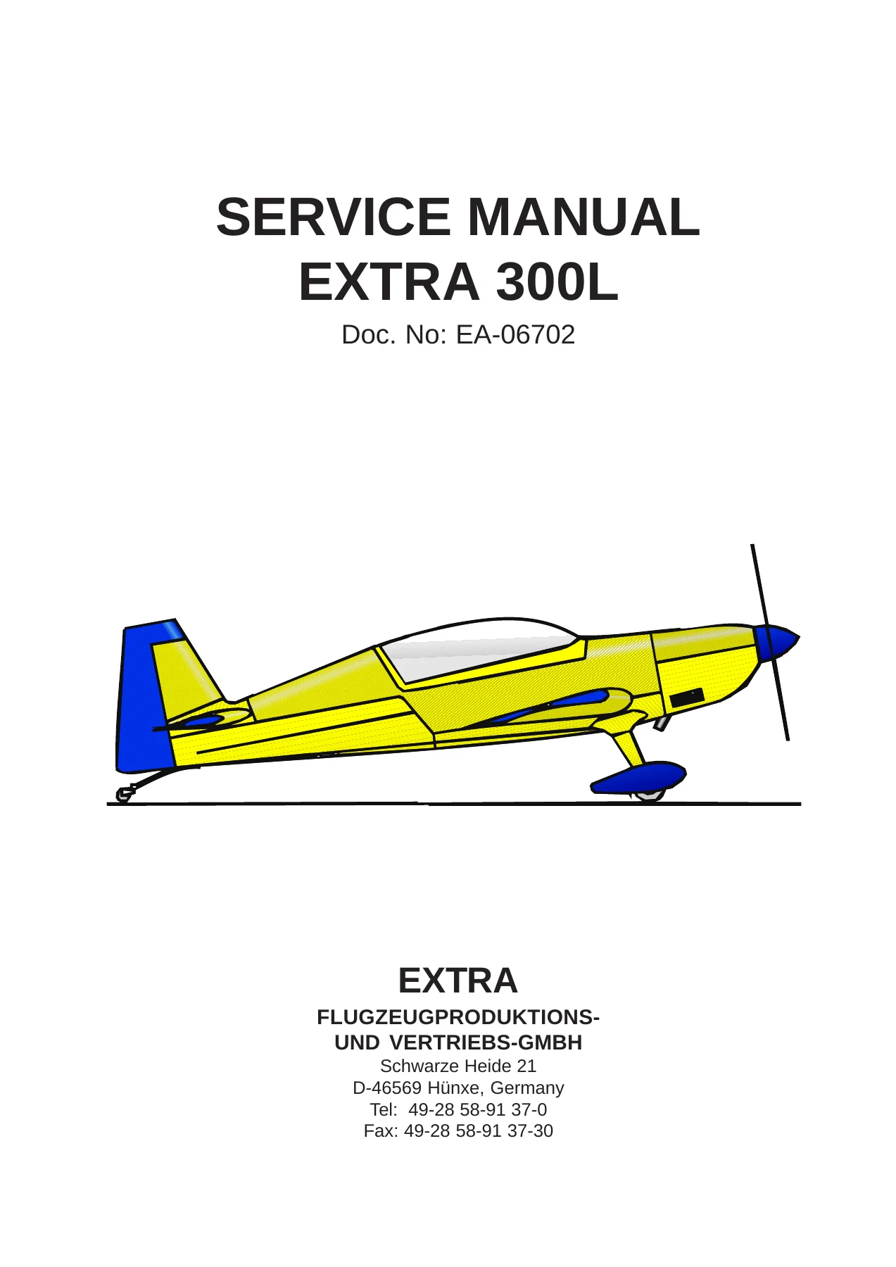
This is the complete service manual for the Extra 300L aerobatic aircraft, published by Extra Flugzeugproduktions- und Vertriebs-GmbH under document number EA-06702. The manual spans from the first edition issued in June 1995 through the 11th revision dated 11 December 2019, with technical content approved under DOA reference EASA 21J.073. It is written for licensed maintenance personnel and covers the airframe, engine, propeller, systems, and structural repair procedures required to service and maintain the Extra 300L.

File Details

  • Manual Type: Service Manual
  • Brand: Extra Flugzeugproduktions- und Vertriebs-GmbH
  • Model: Extra 300L
  • Document Number: EA-06702
  • Edition: 1st Edition, 1 June 1995
  • Latest Revision: 11th Revision, 11 December 2019
  • Language: English
  • Page Count: 491 pages
  • File Format: PDF

Chapters Covered

  • Chapter 01 – Introduction
  • Chapter 02 – How to Use the Service Manual
  • Chapter 03 – General Description
  • Chapter 04 – Airworthiness Limitations
  • Chapter 05 – Time Limits / Maintenance Checks
  • Chapter 06 – Dimensions and Areas
  • Chapter 07 – Lifting and Shoring
  • Chapter 08 – Leveling and Weighing
  • Chapter 09 – Towing and Taxiing
  • Chapter 10 – Parking, Mooring, Storage and Return to Service
  • Chapter 12 – Servicing
  • Chapter 20 – Standard Practices – Airframe
  • Chapter 23 – Communications
  • Chapter 24 – Electrical Power
  • Chapter 25 – Equipment and Furnishings
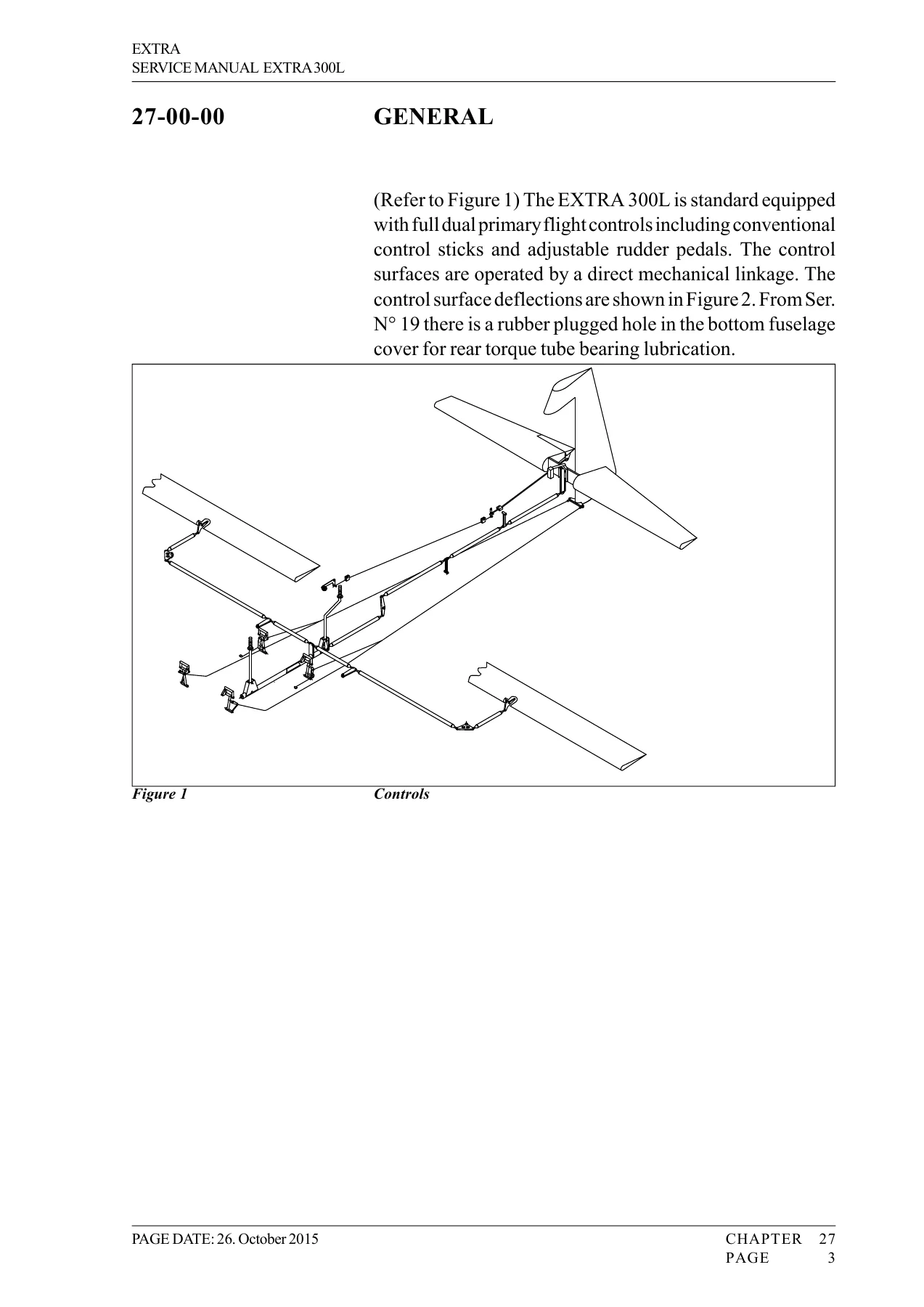
  • Chapter 27 – Flight Controls
  • Chapter 28 – Fuel
  • Chapter 31 – Indication / Recording Systems
  • Chapter 32 – Landing Gear
  • Chapter 33 – Lights
  • Chapter 34 – Navigation
  • Chapter 51 – Standard Practices and Structures – General
  • Chapter 53 – Fuselage
  • Chapter 55 – Stabilizers
  • Chapter 57 – Wings
  • Chapter 61 – Propeller
  • Chapter 71 – Power Plant
  • Chapter 72 – Engine
  • Chapter 73 – Engine Fuel and Control
  • Chapter 77 – Engine Indicating
  • Chapter 78 – Exhaust
  • Chapter 79 – Oil System
  • Chapter 91 – Charts (Wiring Diagrams)

This Extra 300L service manual goes well beyond routine maintenance. It documents the aircraft’s construction in detail – steel tube fuselage covered with fabric and composite panels, fiber composite wings and stabilizers, and a fixed main landing gear with a full-swivel tail wheel. The General Description chapter gives a full survey of the aircraft’s systems, including the flight control system, brake system, powerplant, fuel system, electrical system, and standard instrument installations for both front and rear cockpits.

The manual provides a complete scheduled maintenance program with inspection intervals at 25, 50, 100, 200, 300, 400, 500, and 1000 hours, plus an annual inspection equal to the 100-hour check. Lubrication charts for 25, 50, and 100-hour intervals are included, along with a drain and vent hole chart. The 1000-hour Significant Items Inspection is documented in detail, covering the wing, ailerons, vertical stabilizer, rudder, horizontal stabilizer, elevator, fuselage, flight controls, landing gear, engine compartment, and hardware. Unscheduled maintenance checks are covered for propeller strikes, hard landings, engine fires, lightning strikes, and flightline inspections.

Structural Repair and Composite Work

Structural repair guidance covers reinforced glass and carbon fiber components, sandwich material, laminates, spars, and steel components, with specific damage classification criteria and repair limits. The manual includes detailed procedures for repairing minor surface damage, complete sandwich damage, and large laminate damage, including scarfing, vacuum bagging, and curing cycles. Re-bonding procedures for bushings in the empennage spars and wing main spar flange bushings are documented step by step. Repair of steel components includes TIG welding guidance and material specifications for both early and later serial number ranges.

Control surface balancing is covered with weighing and moment determination procedures, including permissible weights and moments for the ailerons, elevator, rudder, and trim tab. The manual also details the materials used in repairs, including epoxy systems, glass and carbon fiber fabrics, core materials, paints, steel tubing, and aluminum components, with manufacturer and supplier information.

Systems and Components

Flight control systems are covered in depth, including aileron, elevator, and rudder rigging procedures, control rod lengths, bellcrank installation, and free play limits. The fuel system chapter details the wing tanks, center tank, acro tank with flop tube, fuel selector valve, gascolator, and electrical boost pump, including both 42 L and 60 L center tank configurations. Electrical power covers the battery, master relay, alternator, and drive belt. Landing gear, wheels, and brakes are documented with Cleveland wheel and brake assemblies, master cylinder, and tail wheel procedures.

Communications and navigation equipment includes the Becker AR 3201 VHF radio, intercom systems, transponder installations, pitot/static system, altimeter, airspeed indicator, magnetic compass, and turn and bank indicator. Chapter 91 provides wiring diagrams for power generation, magneto systems, nav/strobe lights, fuel gauges, COM equipment, alternators, fuel boost pumps, stall warning, transponders, ELT systems, and more.

Complete PDF Bookmark Tree

Complete Bookmarks

The complete bookmarks in the β€œExtra 300L Service Manual 1995-2019 EA-06702 – Complete Aerobatic Aircraft Workshop Guide” are as follows:

MM 300L Title Pagep. 1
CH00p. 2
CH01p. 10
CH02p. 17
CH03p. 25
Chapter 03p. 26
03-00-00 GENERALp. 27
03-10 DESCRIPTIONp. 28
03-10-01 Constructionp. 28
03-10-02 Flight Control Systemp. 28
03-10-03 Brake Systemp. 29
03-10-04 Powerplantp. 29
03-10-05 Fuel Systemp. 30
03-10-06 Electrical systemp. 30
03-10-07 Instrumentsp. 31
CH04p. 32
Chapter 04p. 34
04-00-00 Generalp. 35
04-00-01 Temperature Limitp. 35
04-00-02 Operating Timep. 35
04-10-00 Life Limited Componentsp. 37
04-10-01 Generalp. 37
04-10-02 Replacement Timep. 37
04-10-03 Service Life Limited Componentsp. 37
04-20-00 Major Inspection
CH05p. 38
CH06p. 78
Chapter 06p. 79
06-00-00 Generalp. 80
06-10-00 Main Datap. 81
06-10-01 Main Dimensionsp. 81
06-10-02 Wingp. 81
06-10-03 Horizontal Tailp. 82
06-10-04 Elevatorp. 82
06-10-05 Vertical Tailp. 82
06-10-06 Rudderp. 82
CH07p. 84
CH08p. 90
CH09p. 97
Chapter 09p. 98
09-00-00 GENERALp. 99
09-10-00 Towingp. 99
09-20-00 Taxingp. 99
CH10p. 101
Chapter 10p. 102
10-00-00 GENERALp. 103
10-10-00 Parking / storagep. 104
10-20-00 Mooringp. 105
10-30-00 Return to servicep. 106
CH12p. 107
Chapter 12p. 108
12-00-00 GENERALp. 109
12-10-00 Replenishingp. 110
12-10-01 Refuelingp. 110
12-10-02 Defuelingp. 112
12-10-03 Fuel Drainsp. 112
12-10-04 Replenishment of Engine Oilp. 112
12-10-05 Oil Changep. 116
12-10-06 Replenishment of Brake Fluidp. 117
Figure 1 Replenishment of Brake Fluidp. 118
12-10-07 Tire Inflationp. 119
12-20-00 Scheduled Servicingp. 120
12-20-01 Exterior Cleaningp. 120
12-20-02 Interior Cleaningp. 121
12-20-03 Engine Cleaningp. 121
12-30-00 Unscheduled servicingp. 123
12-30-01 Removal of Snow and Icep. 123
CH20p. 124
CH23p. 147
CH24p. 154
CH25p. 168
CH27p. 175
CH28p. 205
CH31p. 239
CH32p. 249
CH33p. 263
33-10-00 Flight Compartment
33-40-00 Exterior
33-41-00 Maintenance Practices
33-41-01 Navigation/Strobe Lights Removal/Installation
33-41-02 Strobe Light Power Supply Removal/Installation
CH34p. 272
CH51p. 282
CH53p. 324
CH55p. 341
CH57p. 352
CH61p. 365
CH71p. 374
CH72p. 385
CH73p. 393
CH77p. 409
CH78p. 417
CH79p. 424
CH91p. 438
CH91 Wiringsp. 441
EA-96102_0D_3L0903_Power-Gen 20151015p. 441
EA-9C102_02a Magneto System 20080711p. 442
EA-93102_2c 300907 MAGNETO SYSTEM 20090303p. 443
EA-93102_3a 300910 NAV-STROBE LIGHTS 20060208p. 444
EA-93102_04a 300908 FUEL GAGES 20051215p. 445
Schematics
93102_04a 300908a Fuel-Gages.schp. 445
Components
CB10p. 445
CB10-p. 445
KOPF RAHMENp. 445
KOPF RAHMENp. 445
–p. 445
–p. 445
–p. 445
–p. 445
–p. 445
–p. 445
–p. 445
–p. 445
–p. 445
Rp. 445
Rp. 445
R-1p. 445
R-2p. 445
Rp. 445
R-1p. 445
R-2p. 445
Nets
#20p. 445
Pins
CB10_p. 445
R_1p. 445
R_2p. 445
_p. 445
_p. 445
_p. 445
_p. 445
_p. 445
_p. 445
_p. 445
_p. 445
NetLabels
#20p. 445
#20p. 445
#20p. 445
#20p. 445
#20p. 445
#20p. 445
#20p. 445
#20p. 445
#20p. 445
#20p. 445
Netp. 445
_p. 445
NetCB10p. 445
CB10_p. 445
NetR_1p. 445
R_1p. 445
NetR_2p. 445
R_2p. 445
Nets
#20
NetLabels
#20p. 445
Pins
CB10_p. 445
R_1p. 445
R_2p. 445
_p. 445
Net
_p. 445
NetCB10
CB10_p. 445
NetR_1
R_1p. 445
NetR_2
R_2p. 445
EA-9E102_05_l1 COM S-E GERΓ„T 20141004p. 446
EA-93102_06b 300915 AUDIO SWITCHES_JACKS 20060215p. 447
Schematics
93102_06b 300915b Audio Jacks.schp. 447
Components
-2p. 447
-1p. 447
-2p. 447
-1p. 447
-2p. 447
-1p. 447
-2p. 447
-1p. 447
PHONE-BUCHSE PILOTp. 447
PHONE-BUCHSE COPILOTp. 447
MIC-BUCHSE COPILOTp. 447
MIC-BUCHSE PILOTp. 447
KOPF RAHMENp. 447
J4p. 447
J4-1p. 447
J4-2p. 447
J4-3p. 447
J4-4p. 447
EA-93102_7d 300913 LOW VOLTAGE WARNING SYSTEM 20101026p. 448
EA-93102_8c 300914 SMOKE SYSTEM 20051129p. 449
EA-96102_09_ BATTERY CIRCUIT 20090501p. 450
EA-93102_10e 300912 ALTERNATOR SYSTEM 20101026p. 451
EA-93102_11b 300905 FUEL BOOST PUMP 20060209p. 452
Schematics
93102_11b 300905b Fuel Boost Pump.schp. 452
Components
–p. 452
–p. 452
KOPF RAHMENp. 452
CB6p. 452
CB6p. 452
CB6-p. 452
CB6p. 452
CB6-7p. 452
CB6-8p. 452
S2p. 452
S2-1p. 452
S2-2p. 452
S2-3p. 452
EA-93102_12a 300904 STALL WARNING SYSTEM 20060209p. 453
EA-93102_13a 300906 TRANSPONDER ATC-2000 20051207p. 454
EA-94102-14c Pedal adjust 20110225p. 455
EA-96102_15 ACCELEROMETER (OPTIONAL) 19930118p. 456
EA-93102_16a 300921 EXTERNAL POWER (optional) 20051013p. 457
EA-93102_18a 300927 BATTERY CHARGER 20050713 newp. 458
EA-93102_19 300928 TRANSPONDER TRT-600 20051021p. 459
EA-93102_20a 300929a TRANSPONDER TRT800-H 20140324p. 460
EA-93102_21b 300930 TRANSPONDER GTX330_328 20120909p. 461
EA-93102_22l1 300931TRANSPONDER BXP6401 20060404p. 462
EA-93102_23 300932 TRANSPONDER KT-73 20051123p. 463
EA-93102_24 300933 TRANSPONDER KT-76A 20051208p. 464
EA-93102_25 300934 TRANSPONDER GTX327 20051103p. 465
Schematics
93102_25 300934 GTX327.schp. 465
Components
ANTENNAp. 465
ANTENNA-1p. 465
KOPF RAHMENp. 465
1SHp. 465
1SH-p. 465
2SH-Ap. 465
3SH-Ap. 465
3SH-A-1p. 465
4SH-Ap. 465
J3302p. 465
J3302-1p. 465
EA-93102_26l1 300935 TRANSPONDER ATC4401 20060404p. 466
EA-93102_27 300936 Volt-Ampere 20060117p. 467
EA-93102_28l1 300937 EDM700 20110426p. 468
EA-93102_29l2 300938 EDM800 20110426p. 469
EA-93102_30 300939 RPM INDICATION 20051215p. 470
EA-96102_31_ 3L0940 STARTER ENGAGED LIGHT 20060130p. 471
EA-93102_33 300942 FUEL FLOW FS-450 20060131p. 472
EA-93102_34 300943 Oil Press_Temp Indication 20060210p. 473
EA-9D102_34a 3D0943 Oil Temp (Press) 20130729p. 474
EA-96102_38_ 3L0947 INTERCOM PM 1200R 20131029p. 475
EA-94102_39 SMOKE SYSTEM (Single Pump) 3S0948 20060718p. 476
Schematics
94102_39 3S0948 SMOKE Eine Pumpe.schp. 476
Components
KOPF RAHMENp. 476
CB11p. 476
CB11-p. 476
K4p. 476
K4-1p. 476
K4-2p. 476
K4-3p. 476
K4-4p. 476
K4-5p. 476
K5p. 476
K5-1p. 476
K5-2p. 476
K5-3p. 476
K5-4p. 476
K5-5p. 476
P1p. 476
P1-1p. 476
P1-2p. 476
S5p. 476
S5-1p. 476
S5-2p. 476
S5-3p. 476
S6p. 476
S6-1p. 476
S6-2p. 476
S6-3p. 476
S15p. 476
S15-1p. 476
S15-2p. 476
S15-3p. 476
S16p. 476
S16-1p. 476
S16-2p. 476
Nets
#16p. 476
Pins
CB11_p. 476
K4_1p. 476
K4_2p. 476
K4_3p. 476
K4_4p. 476
K4_5p. 476
K5_1p. 476
K5_2p. 476
K5_3p. 476
K5_4p. 476
K5_5p. 476
P1_1p. 476
P1_2p. 476
S5_1p. 476
S5_2p. 476
S5_3p. 476
S6_1p. 476
S6_2p. 476
S6_3p. 476
S15_2p. 476
S15_3p. 476
S16_1p. 476
S16_2p. 476
NetLabels
#16p. 476
#16p. 476
#16p. 476
#16p. 476
#16p. 476
#16p. 476
#16p. 476
#16p. 476
#16p. 476
#16p. 476
#16p. 476
#16p. 476
#16p. 476
#16p. 476
#16p. 476
#16p. 476
#16p. 476
#16p. 476
#16p. 476
#20p. 476
#20p. 476
#20p. 476
#20p. 476
#20p. 476
#20p. 476
BLKp. 476
Pins
P1_1p. 476
NetLabels
BLKp. 476
NetCB11p. 476
CB11_p. 476
NetS15_1p. 476
S15_1p. 476
REDp. 476
Pins
P1_2p. 476
NetLabels
REDp. 476
Nets
#16
NetLabels
#16p. 476
#20p. 476
Pins
CB11_p. 476
K4_1p. 476
K4_2p. 476
K4_3p. 476
K4_4p. 476
K4_5p. 476
K5_1p. 476
K5_2p. 476
K5_3p. 476
K5_4p. 476
K5_5p. 476
P1_1p. 476
P1_2p. 476
S5_1p. 476
S5_2p. 476
S5_3p. 476
S6_1p. 476
S6_2p. 476
S6_3p. 476
S15_2p. 476
S15_3p. 476
S16_1p. 476
S16_2p. 476
BLK
NetLabels
BLKp. 476
Pins
P1_1p. 476
NetCB11
CB11_p. 476
NetS15_1
S15_1p. 476
RED
NetLabels
REDp. 476
Pins
P1_2p. 476
EA-93102_41a 300950 ELT POINTER 3000 20061018p. 477
EA-9D102_42a ELT ARTEX ME406 3D0951 20120722p. 478
EA-93102_43 300952 TRANSPONDER BXP-6401-X_ENC 20041024p. 479
Schematics
93102_43 300952 BXP6401 + ENC.schp. 479
Components
ANTENNAp. 479
ANTENNA-1p. 479
KOPF RAHMENp. 479
1SHp. 479
1SH-p. 479
2SH-Ap. 479
4SH-Ap. 479
4SH-A-1p. 479
J6p. 479
J6-1p. 479
J8p. 479
EA-96102_46_l1 3L0955 EFD1000PFD 20110419p. 480
EA-96102_48_l2 3L0957 GNC420W 20120424p. 481
EA-96102_49_l1 3L0958 ATTITUDE GYRO 20131107p. 482
EA-9E102_53 3E0962 Landing Light 20101210p. 483
EA-93102_58_ 300918 EGT-CHT Westach 20111121p. 484
EA-9C102_58 EGT_CHT INDICATION 20111121p. 485
EA-9D102_58a 3D0954 EGT-CHT Indication 20130729p. 486
EA-93102_59 300927 FLIGHT TIMER 20110509p. 487
EA-9E102_62a_ COM-GPS GTN-635 20140623p. 488
EA-9E102_63a_ COM-NAV-GPS GTN-650_750 20140623p. 489
EA-9D102_64a_ XPDR GTX-33 20140627p. 490
EA-9D102_65_ AUDIO GMA-35 20120903p. 491

For the powerplant, the manual covers the Lycoming AEIO-540-L1B5, AEIO-540-L1B5D, and AEIO-580-B1A engines, including the Christen inverted oil system that allows sustained inverted flight. Engine removal and installation procedures, fuel system servicing, exhaust system maintenance, and engine indicating system troubleshooting are all documented. The propeller section covers the MT-Propeller MTV-9-B-C/C 200-15, MTV-14-B-C/C 190-17, and MTV-9-B-C/C 198-25 models, with governor and RPM vernier control cable rigging procedures.

Specifications and Operating Limits

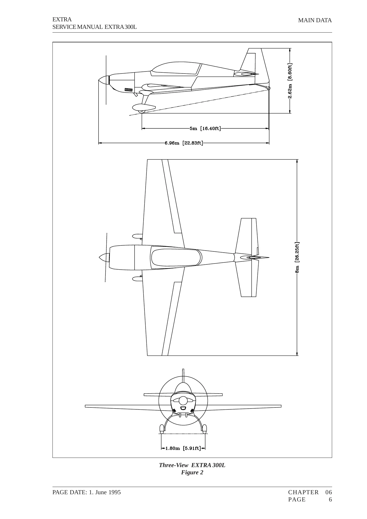
The manual includes dimensions and areas data: length 6.96 m, height 2.62 m, span 8.00 m, wheelbase 5.00 m, and wheel track 1.80 m. Wing area is 10.7 mΒ² with a root chord of 1.85 m and tip chord of 0.87 m. Maximum takeoff weight is 950 kg in normal category, 820 kg for single-seat acrobatic, and 870 kg for two-seat acrobatic. Fuel capacities are 171 L total for Configuration 1 and 189 L total for Configuration 2. Engine oil capacity is 16 U.S. quarts (15.18 L). Tire pressure is 3.4 bar (49.3 psi) for both main wheels.

Airworthiness limitations include a 6000-flight-hour life limit for the wing, aileron, vertical stabilizer, rudder, horizontal stabilizer, elevator, and landing gear spring. The composite structure is qualified to a maximum temperature of 72Β°C (162Β°F). Recommended replacement times are given for batteries, hoses, seat belts, and other components. Torque values are provided for standard metric and AN hardware, plus special torque values for critical airframe connections.

What You Can Do With This Manual

With the Extra 300L service manual, you can perform scheduled inspections, troubleshoot systems, remove and install major components, rig flight controls, repair composite structures, service the fuel and oil systems, maintain the landing gear and brakes, and perform engine-related maintenance tasks. The manual includes torque values, rigging dimensions, control surface deflection tolerances, fluid capacities, tire pressures, and other specifications needed to work on the aircraft correctly.

The flight control rigging procedures are especially valuable, covering neutral position setup, control rod lengths, aileron and elevator deflection tolerances, rudder cable installation with clamping specifications, and trim tab rigging. The manual also documents the free play limits for aileron, elevator, and trim tab, which are critical for safe operation of an aerobatic aircraft.

Correct procedures and specifications matter on an aerobatic aircraft like the Extra 300L, where control system rigging, structural integrity, and engine reliability are critical. This manual gives you the manufacturer’s guidance directly, so you can work with confidence rather than guesswork. Whether you are an owner performing routine maintenance or a shop undertaking major repairs, the procedures and specifications in this manual are the authoritative reference for the Extra 300L.

IMAGES PREVIEW

Extra 300L Service Manual 1995-2019 EA-06702 - Complete Aerobatic Aircraft Workshop Guide β€” PDF page 1 preview
Extra 300L Service Manual 1995-2019 EA-06702 - Complete Aerobatic Aircraft Workshop Guide β€” PDF page 83 preview
Extra 300L Service Manual 1995-2019 EA-06702 - Complete Aerobatic Aircraft Workshop Guide β€” PDF page 177 preview

Your purchase includes an instant PDF download – no shipping, no waiting. The file works on any device and can be printed if you prefer a paper copy in the hangar.
Reviews

There are no reviews yet.

Be the first to review “Extra 300L Service Manual 1995-2019 EA-06702 – Complete Aerobatic Aircraft Workshop Guide”

What Our Customers Say

β˜…β˜…β˜…β˜…β˜… Live reviews from customers
Loading customer reviews...
0
    0
    Your Cart
    Your cart is emptyReturn to Shop
    πŸ›’
    Recently Purchased
    πŸ•’ verified order