
EXTRA 500 Maintenance Manual EA-0B702 – Complete Turboprop Aircraft Workshop Manual PDF
Original price was: $44.95.$26.95Current price is: $26.95.
The complete 626-page EXTRA 500 maintenance manual, document EA-0B702, 2nd Edition dated 30 March 2012. Covers airframe, systems, engine installation, landing gear, composite structure repair, inspection intervals, component life limits and the full wiring schematic set.
Description
EXTRA 500 Maintenance Manual – Document EA-0B702
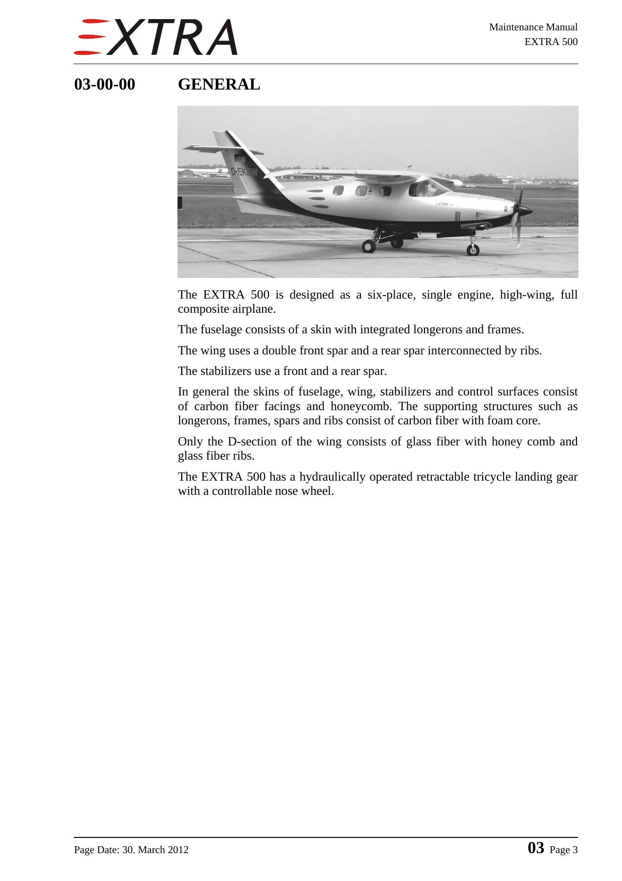
This is the complete maintenance manual for the EXTRA 500, the six-place, single-engine, high-wing, full composite airplane built by EXTRA Flugzeugproduktions- und Vertriebs-GmbH. The document carries the number EA-0B702 and is issued as the 2nd Edition dated 30 March 2012, with the technical content approved under DOA N° EASA.211.073 and EASA Major Change Approval N° 10035367. It is written for the maintenance technician rather than the pilot, and it goes well beyond a routine service schedule: it documents the airframe, the installed systems, the inspection intervals, the component life limits and the composite repair methods that keep an all-composite turboprop airworthy. If you own, operate or maintain an EXTRA 500, this EXTRA 500 maintenance manual is the reference that answers the questions the aircraft itself does not.
File Details
- Manual type: Aircraft maintenance manual covering airframe, systems, engine installation and structures
- Manufacturer: EXTRA Flugzeugproduktions- und Vertriebs-GmbH, Schwarze Heide 21, 46569 Hünxe, Germany
- Aircraft covered: EXTRA 500 – six-place, single-engine, high-wing, full composite airplane
- Document number: EA-0B702
- Edition: 2nd Edition, complete manual except Chapter 4
- Revision date: 30 March 2012, with Chapter 4 pages dated 31 March 2011
- Language: English
- Length: 626 pages
- Format: PDF
Chapters Covered in the EXTRA 500 Maintenance Manual
- Chapter 01 – General: address and contact details, related documents, special tools, trade marks and safety.
- Chapter 02 – How to Use the Maintenance Manual: manual and chapter set-up, page and figure numbering, notes and safety notes, revisions, service bulletins and checklists.
- Chapter 03 – General Description: airframe construction, composite materials, wing and stabilizer structure, and the hydraulically operated retractable tricycle landing gear.
- Chapter 04 – Airworthiness Limitations: temperature limits, operating time, life-limited components and replacement times.
- Chapter 05 – Time Limits and Maintenance Checks: time between overhaul, replacement and inspection, 100-hour and 1000-hour checks, scheduled maintenance charts, flightline inspections and unscheduled checks.
- Chapter 06 – Dimensions and Areas: main dimensions, wing, horizontal and vertical tail, control surface areas, settings and deflections.
- Chapter 07 – Lifting and Shoring: jacking points and the lifting procedure.
- Chapter 08 – Leveling and Weighing: longitudinal and lateral leveling.
- Chapter 09 – Towing and Taxiing.
- Chapter 10 – Parking, Mooring, Storage and Return to Service.
- Chapter 11 – Placards and Markings.
- Chapter 12 – Servicing: refueling, draining and fuel drains, engine oil and oil change, brake fluid and the brake bleeding procedure, tire inflation, main gear shock absorber oil, cleaning and the lubrication chart.
- Chapter 20 – Standard Practices, Airframe: metric bolt widths across flats, torque values, special torque values, measuring techniques, coin tapping, flexible hoses, fittings, Bowden cables, engine controls, rod ends, fork ends and bolt installation in CFRP structures.
- Chapter 21 – Air Conditioning: SCEET hoses, compression, distribution, pressurization control, cooling and temperature control.
- Chapter 22 – Auto Flight: S-TEC System 55X autopilot description, roll, pitch and yaw servos, clutches, driving wheels, bridle cables, cable clamps, trim servo, pressure transducer, yaw amplifier, programmer/computer and turn coordinator.
- Chapter 23 – Communications: speech communication, audio integrating, intercom system, antennas and static discharging.
- Chapter 24 – Electrical Power: DC generation, starter-generator, generator control unit, standby alternator, battery, external power, distribution and the E-box.
- Chapter 25 – Equipment and Furnishing: paneling, flight compartment, seats, passenger compartment, storage boxes and the baggage compartment.
- Chapter 27 – Flight Controls: control cable tensions, control springs, ailerons, rudder, elevator and tab, and the complete flap system including rigging, track adjustment and asymmetry senders.
- Chapter 28 – Fuel: tank storage, sealant repair and leakage test, drains, pressure relief and float valves, transfer filter and pump, jet pump, distribution, selector valve, fuel filter, electrical fuel pumps and indication.
- Chapter 29 – Hydraulic Power.
- Chapter 30 – Ice and Rain Protection: airfoil boots, pressure regulator, ejector valve, boots timer, air intake anti-ice, pitot, static and stall warning heat, windshield heat, propeller heat and the ice light.
- Chapter 31 – Indication and Recording Systems: instrument and control panels, central warning systems and central display systems.
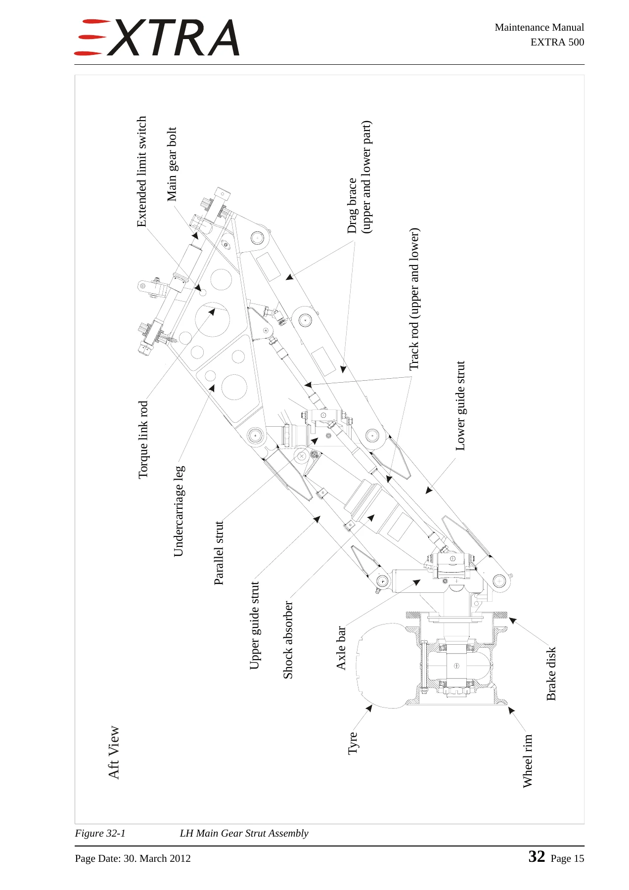
- Chapter 32 – Landing Gear: main gear strut assembly, parallel strut, axle bar, shock absorber, main and nose gear doors, extension and retraction, hydraulic system and power pack, actuators, wheels and brakes, steering and position switches.
- Chapter 33 – Lights: flight compartment, passenger compartment and exterior lighting.
- Chapter 34 – Navigation: pitot and static pressure systems, flight environmental data, attitude and direction, and positioning equipment.
- Chapter 51 – Standard Practices and Structures, General: access panel identification, damage classification and repair criteria, materials, control surface balancing and composite repair procedures.
- Chapter 52 – Doors: passenger and crew door plus emergency exit.
- Chapter 55 – Stabilizers: horizontal stabilizer, elevator, vertical stabilizer, fin tip and rudder.
- Chapter 56 – Windows: windshield and cabin windows.
- Chapter 57 – Wings: centre wing removal and installation, wing tips, flaps and ailerons.
- Chapter 61 – Propeller.
- Chapter 71 – Power Plant: engine removal and installation, cowling, engine mount and shock mounts, air intakes and engine drains.
- Chapter 73 – Engine Fuel and Control.
- Chapter 74 – Ignition.
- Chapter 76 – Engine Controls: power control, engine control mounting bracket, throttle quadrant, power lever and condition lever Bowden cables.
- Chapter 77 – Engine Indicating: N1 tachometer, torque transducer and torque switch, N2 sensor, thermocouple wiring and the integrated engine instrument systems.
- Chapter 78 – Exhaust.
- Chapter 79 – Oil: oil supply tank, overpressure valves, external scavenge oil filter, oil cooler, thermostat, oil lines and indication.
- Chapter 80 – Starting: cranking and motoring.
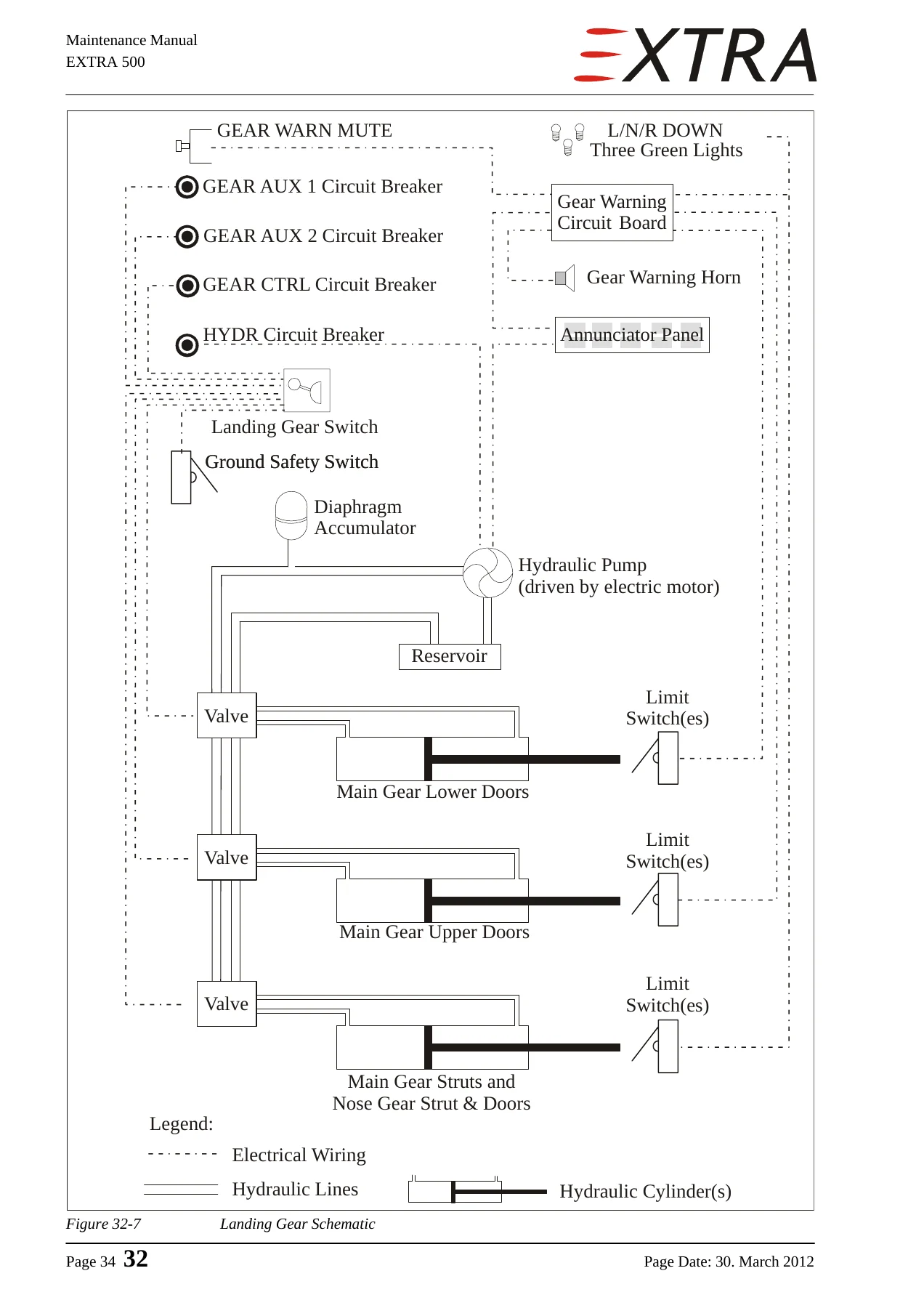
- Chapter 91 – Charts: the electrical schematic set covering cabin pressure control, air conditioning, bleed air, DC generation, E-box, external power, battery charge, DC distribution, autopilot, flap system, fuel quantity and low fuel warning, pitot-static-stall heat, anti-ice intake, windshield heat, boots, airspeed warning, annunciator panel, landing gear control and warning, lights, dimming, IFD units, attitude gyro, weather detection, traffic, datalink, DME, transponder, propeller heat, door warning, fuel pump and flow, start and ignition, and panel fan.
Read as a whole, this EXTRA 500 workshop manual is a system-by-system teardown of a composite turboprop. Every chapter follows the same disciplined pattern: a description of how the system works, a troubleshooting table that maps a complaint to a probable cause and a remedy, then removal, installation, disassembly and assembly procedures with the key items called out step by step. Torque values, tolerances, capacities and adjustment dimensions sit alongside the procedures rather than being buried in an appendix, and cross-references point to the companion Rolls-Royce and MT-Propeller publications where vendor-level work is required. The result is a document you can open at the failure and work outward from, instead of guessing.
Airworthiness Limits, Inspection Intervals and Component Life
The airworthiness limitation section is where this manual earns its place in a maintenance library. Temperature limits for the composite structure, the 100-hour and 1000-hour check schedules with their tolerance bands, the life-limited airframe components and the replacement times for consumables such as filters, hoses, batteries and seat belt webbing are all stated with the intervals and conditions attached. The maintenance check charts break the work down into operational checks, fuel system, oil system, bleed air, air inlet and exhaust, engine and accessories, propeller and governors, cabin and equipment, fuselage, wing assembly, control systems and surfaces, landing gear, wheels and brakes, and completion. Unscheduled checks are covered too, so you know exactly what has to be inspected after a hard landing, an engine fire, a propeller strike, a lightning strike or an engine overspeed.
Composite Structures, Damage Classification and Repair
The structural chapters set this manual apart from a typical metal-airframe service book. Damage is classified into four classes with defined limits, and the manual spells out which classes a qualified technician may repair and which require the manufacturer to be contacted first. Repair of reinforced glass and carbon fibre components, repair of sandwich material with foam, honeycomb and plywood cores, scarf overlap ratios, vacuum bagging, curing cycles and the surface refinishing sequence are all described with the consumables and mixing ratios named. Control surface balancing is covered with the weighing and moment procedure, so a repaired or repainted aileron, rudder, elevator or trim tab can be checked back to the permissible values before it goes back on the aircraft.
Wiring Schematics and System Diagrams
Chapter 91 collects the full schematic set in one place. Cabin pressure control, bleed air, air conditioning, DC generation and distribution, the E-box and its circuit board, external power, battery charging, landing gear control and gear warning, flap system, fuel quantity and low fuel warning, pitot, static and stall heat, anti-ice intake, windshield heat, de-ice boots, airspeed warning, the annunciator panel, exterior and interior lighting, dimming, the integrated flight displays, attitude gyro, weather detection, traffic, datalink, DME, transponder, propeller heat, door warning, fuel pump and flow, start and ignition, and the panel fan all have their own drawings with connector pin references, wire colours and splice points. For intermittent electrical faults, that is often the difference between a two-hour job and a two-week one.
Why the Correct Procedures and Specs Matter on the EXTRA 500
The EXTRA 500 is a full composite airframe with a bonded structure. A repair that would be routine on a sheet-metal aircraft can create a stress concentration in a laminated skin if the scarf length, ply direction, resin ratio or cure cycle is wrong, and the manual is explicit that the resin-hardener mixture must be held to within a fraction of a percent. The same applies to hardware: bolt installation into CFRP structures, lightning protection bonding, sealant application on the firewall and pressure cabin, and the specific torque values for the wing attachment bolts, engine mount bolts, main gear former connection bolts and propeller flange bolts are all given here and nowhere else in one volume. Getting those numbers from a generic source is not an option.
IMAGES PREVIEW
Instant PDF Delivery
This EXTRA 500 maintenance manual is supplied as an instant PDF download – no shipping, no waiting for a parcel, and no risk of a page going missing from a paper binder. Open it on a laptop in the hangar, on a tablet at the aircraft, or on a phone while you are on the phone to a supplier, and print only the pages you need for the job in front of you. Searching for a system, a torque figure or a connector reference takes seconds. Whether you are running a scheduled 100-hour inspection, chasing a landing gear fault, repairing a composite panel, rewiring an annunciator circuit or planning an engine removal, the answers are in the document, and the download is available immediately after purchase.
Reviews
There are no reviews yet.