
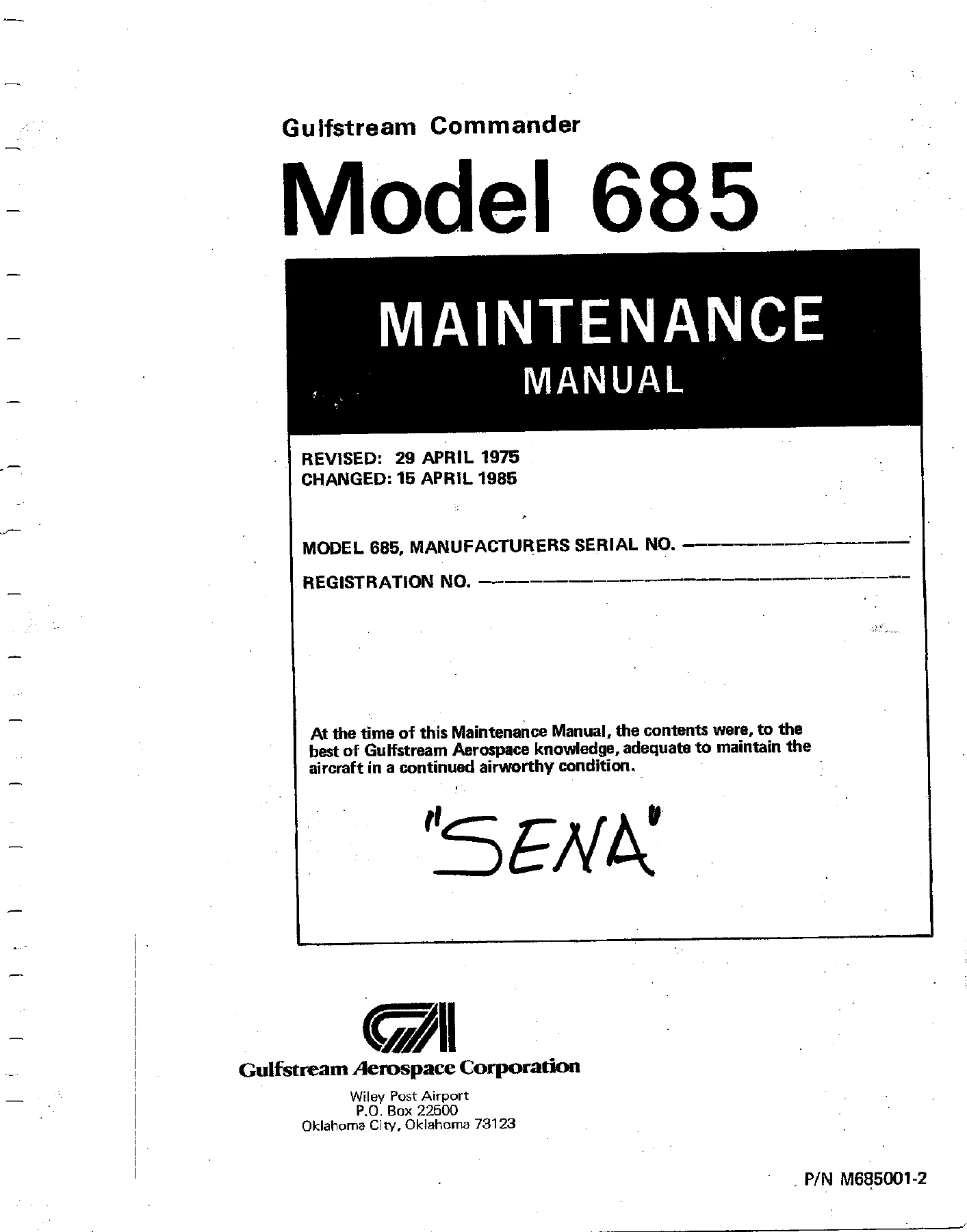
Gulfstream Commander Model 685 Maintenance Manual 1975-1985 PDF Download
Original price was: $39.95.$24.95Current price is: $24.95.
The complete 315-page Gulfstream Commander Model 685 Maintenance Manual covering all aircraft systems, scheduled inspections, servicing procedures, and component overhaul for the Model 685 twin-engine pressurized aircraft. Revised 1975, updated through 1985.
Description
Gulfstream Commander Model 685 Maintenance Manual — 1975 through 1985
This Gulfstream Commander Model 685 Maintenance Manual is the definitive technical reference for the Model 685 high-wing, twin-engine, pressurized aircraft. Revised April 29, 1975, and updated through Change 6 dated April 15, 1985, this 315-page manual delivers comprehensive maintenance, servicing, overhaul, and inspection information for every major aircraft system.
Power for the Commander 685 comes from two Continental GTSIO-520-F or GTSIO-520-K engines driving Hartzell three-blade, constant-speed, full-feathering propellers — and this Gulfstream Commander 685 maintenance manual covers both powerplant and airframe in complete detail. The aircraft seats up to seven passengers, features a standard usable fuel capacity of 256 gallons, and operates up to 25,000 feet with a nominal cabin pressure differential of 4.0 psi.
The Gulfstream Commander 685 maintenance manual is organized into eleven sections that take you from general aircraft description and dimensions through every system: hydraulics, power plant, fuel, landing gear and brakes, flight controls, instruments, environmental, electrical, and optional equipment. Each section includes removal and installation procedures, disassembly and reassembly instructions, adjustment and rigging specifications, troubleshooting charts, and illustrated diagrams. Whether you are a maintenance professional, an A&P mechanic, an aircraft owner, or an enthusiast preserving a Commander 685, this manual gives you the factory-derived procedures and specifications to perform the job correctly.
File Details
- Manual Type: Aircraft Maintenance Manual
- Manufacturer: Gulfstream Aerospace Corporation, Wiley Post Airport, Oklahoma City, Oklahoma
- Model Covered: Commander 685
- Engines: Continental GTSIO-520-F and GTSIO-520-K, six-cylinder, horizontally opposed, geared-drive, fuel-injected, turbocharged
- Propellers: Hartzell HC-H3YN-2F/FC8475+2 or HC-H3YN-2/C8475+2, three-blade, constant-speed, full-feathering
- Language: English
- Page Count: 315 pages
- File Format: PDF
- Original Revision: April 29, 1975
- Final Change: Change 6, April 15, 1985
- Document History: Change 1 (December 5, 1975), Change 2 (April 30, 1976), Change 3 (November 23, 1977), Change 4 (January 27, 1978), Change 5 (May 1, 1981), Change 6 (April 15, 1985)
Chapters Covered
- Section I — General Information: General description, principal dimensions, aircraft structures (fuselage, wing, empennage), aircraft systems overview
- Section II — Servicing: Ground handling — towing, taxiing, parking, mooring, jacking, leveling, emergency procedures, engine ground operation, storage; servicing — engine oil system, landing gear and brake system, batteries, fuel system, hydraulic system, environmental system, oxygen system, wing and empennage deicer system, propeller deicing system; airframe maintenance — fuselage sealing, cabin door seal, windows and windshields, airframe cleaning, couch and seats; lubrication; scheduled inspection and maintenance requirements — preflight inspection, postflight inspection, periodic inspection (50-hour, 100-hour), special inspection requirements, overhaul or replacement schedule, test flight inspection requirements
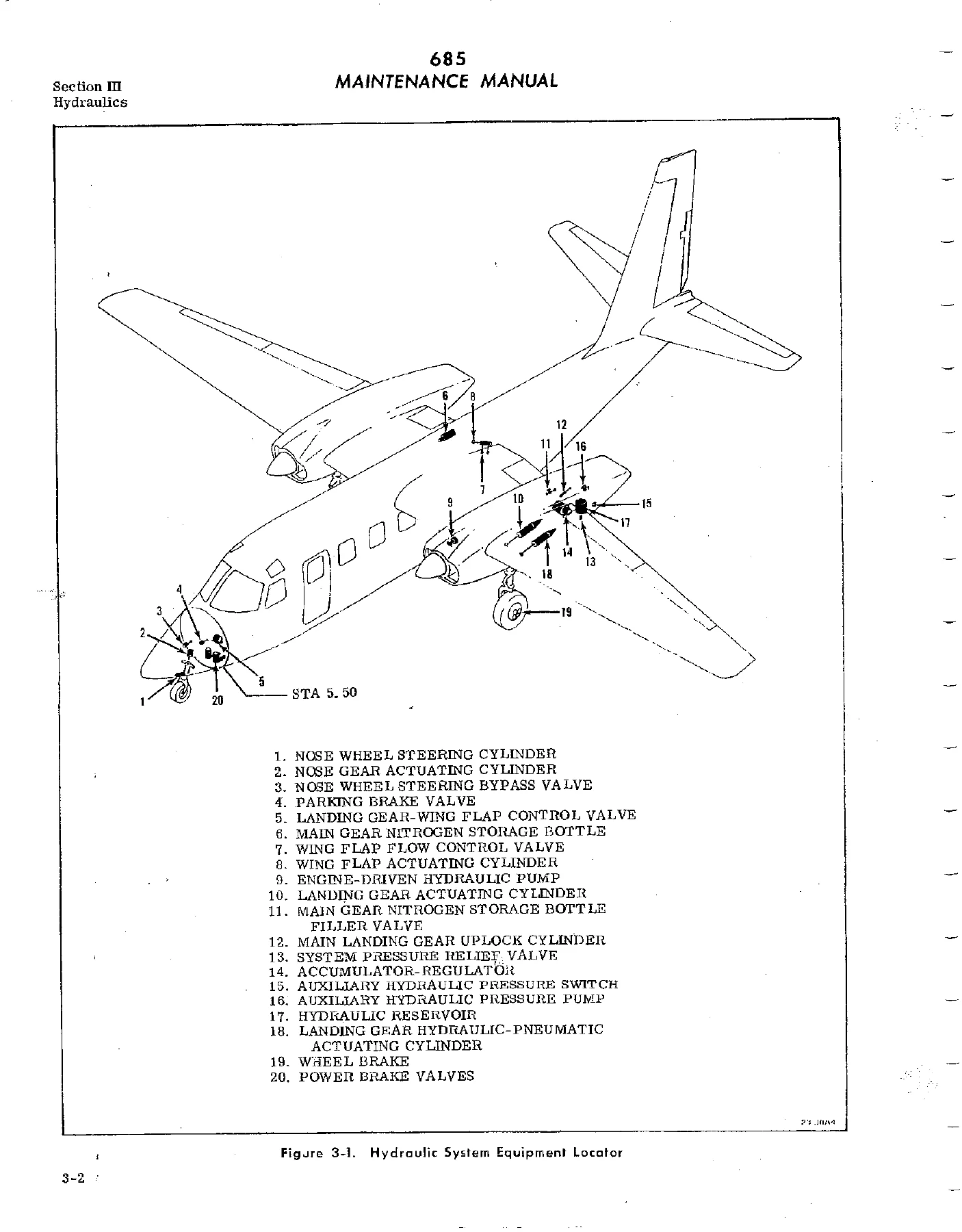
- Section III — Hydraulics: General description, functional test procedures, hydraulic reservoir, shutoff valves, engine-driven hydraulic pump, accumulator-regulator, hydraulic pressure gage, landing gear-wing flap control valve, main landing gear actuating cylinders, main landing gear uplock cylinder, nose landing gear actuating cylinder, wing flap actuating cylinder, parking brake valve, power brake valves, nose wheel steering bypass valve, nose wheel steering cylinder, auxiliary hydraulic system
- Section IV — Power Plant and Propeller: Ignition system (ignition switches, starting vibrator, magneto, ignition harness, spark plugs, starter); fuel injection and air induction systems (fuel-air control unit, fuel manifold valve, fuel injector nozzles, fuel injection pump, turbocharger); oil system; exhaust system; cooling system; engine control cables; engine controls (throttle, mixture, propeller, alternate air); engine accessories (vacuum pump, tachometer-generator, hydraulic pump, propeller governor, generator); engine change (removal, buildup, installation, preoiling, initial ground run); engine mount and cowling; engine conditioning hints; propeller (removal, installation, blade angle checks); troubleshooting
- Section V — Fuel System: General description, fuel system drains, maintenance precautions, defueling and refueling, fuel feed system (fuel sump, fuel shutoff valve, fuel boost pump, fuel screen, fuel filter), fuel vent system, fuel cells (removal, repair, installation), wing sealing, fuel indicating systems (fuel flow indicating system, fuel quantity indicating system)
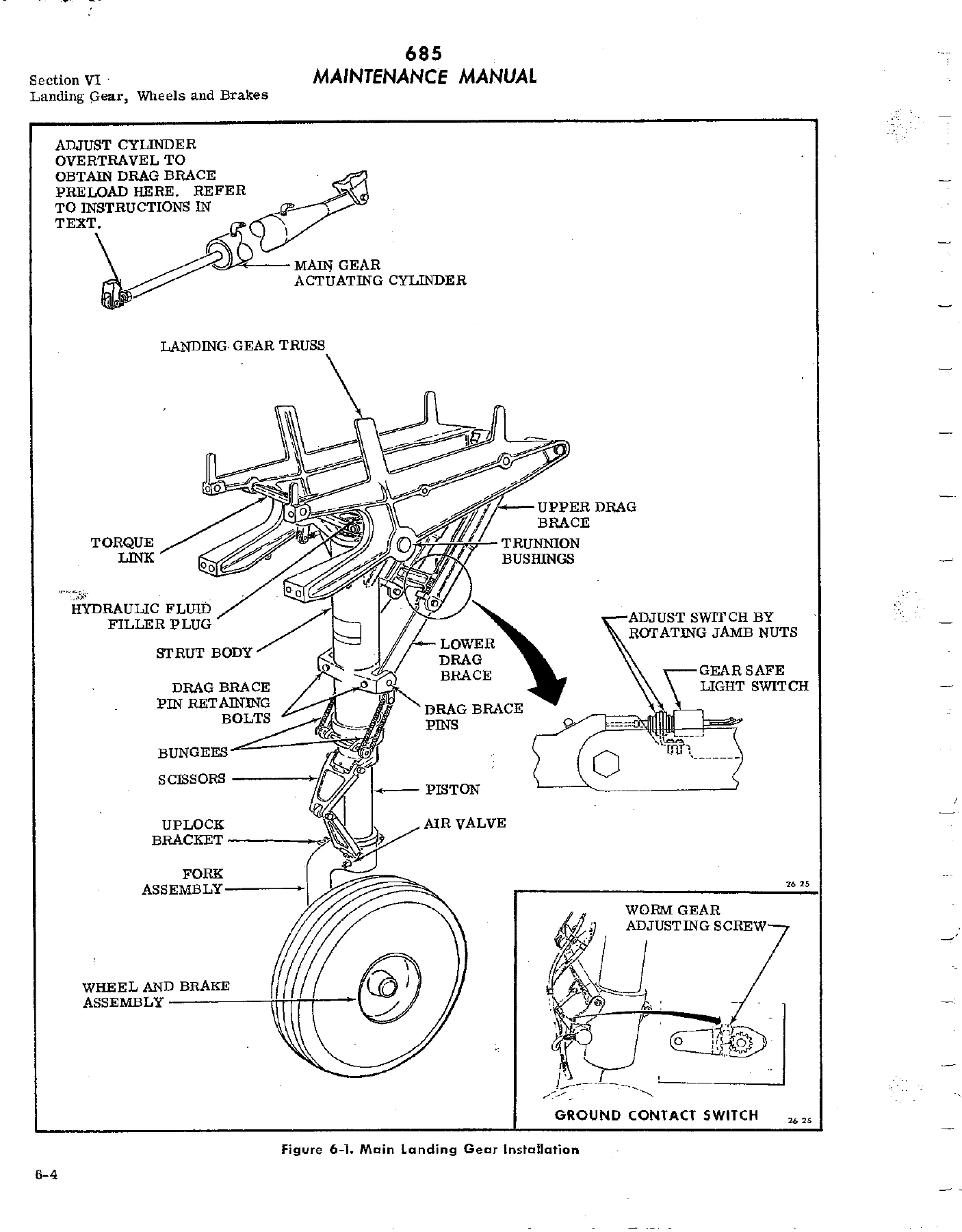
- Section VI — Landing Gear, Wheels and Brakes: Landing gear operation, operational check, main landing gear (strut operation, removal, installation, strut doors, uplocks), nose landing gear (removal, disassembly, reassembly, installation, nose wheel steering, nose gear actuating cylinder, nose gear door rigging), landing gear position indicators and warning system, wheels and brakes (main wheel, nose wheel, brake removal and installation, brake lining wear measurement, power brake valve adjustment, brake and nose wheel steering system bleeding)
- Section VII — Flight Controls: General description, maintenance of flight controls, control cable removal and installation, control surface balancing, control columns, aileron control system, rudder control system, elevator control system, wing flap control system, wing flap position transmitter, control surface trim tab free play measurement
- Section VIII — Instruments: General description, instrument system maintenance, instrument vacuum system (vacuum pumps, vacuum relief valves, turn-and-bank restrictor valve, vacuum gage, vacuum air filter), flight instruments (pitot-static system, alternate static pressure source, airspeed indicator, altimeter, cabin altitude and differential pressure indicator, rate-of-climb indicator, directional gyro, attitude gyro, turn-and-bank indicator, clock, magnetic compass), flap position indicator, rudder and elevator trim tab position indicators, power plant instruments (tachometer indicators and generators, manifold pressure gage, fuel flow indicator, engine gage units), miscellaneous instruments (hydraulic pressure gage, fuel quantity indicator, voltammeters, outside air temperature indicator), instrument panel removal and installation, stall warning system, troubleshooting
- Section IX — Environmental: Environmental system, ventilation air blower, combustion air blower, eyeball air blower, ram air inlet check valve, bleed air valves, combustion heater, heater ignition unit, heater fuel system, pressurization system (cabin pressure controller, outflow valve, safety valve), air conditioning system (compressor and motor, refrigerant condenser, receiver dehydrator, evaporators and expansion valves, refrigeration system charging and servicing), troubleshooting
- Section X — Electrical: General description, power distribution (battery, generator, voltage regulator adjustment, overvoltage relays), annunciator system, lighting system circuits (interior lights, exterior lights, retractable landing lights), hydraulic system circuits (hydraulic shutoff valve, auxiliary hydraulic pump), power plant circuits, fuel system circuits (fuel boost pumps and shutoff valves, fuel quantity indicators, fuel vent heaters), instrument circuits (stall warning system, tachometer-generator, rudder and elevator trim tab position indicators, wing flap position indicator, pitot and stall warning heaters), miscellaneous circuits (cabin door lock and warning light, cigar lighter, spare wires), fuse chart, electrical symbols, wiring diagrams
- Section XI — Optional Equipment: Deicer systems (wing and empennage deicing, deicer boot maintenance and repair, deicer system operational check), propeller deicing, electric windshield wiper system, windshield alcohol anti-ice system, oxygen system, rudder anti-icing system
What This Manual Enables You to Do
With this Gulfstream Commander 685 maintenance manual, you can perform the full range of scheduled and unscheduled maintenance tasks. The preflight, postflight, and periodic inspection checklists give you a structured framework for 50-hour, 100-hour, and annual inspections. The system-specific sections provide step-by-step removal, disassembly, inspection, reassembly, and installation procedures for components ranging from hydraulic pumps and actuating cylinders to fuel cells, landing gear struts, flight control cables, and turbochargers. Adjustment and rigging procedures with specified tolerances and torque values are included throughout — for example, the landing gear drag brace preload adjustment, flight control cable tension settings, and engine control rigging dimensions.
The troubleshooting charts in each section help diagnose common faults: hydraulic system pressure loss, landing gear extension failures, engine starting problems, rough idling, fuel flow discrepancies, heater malfunctions, air conditioning performance issues, and electrical system faults. Wiring diagrams in Section X document the aircraft’s electrical circuits, and the hydraulic system schematics in Section III clarify component relationships and fluid routing.
For structural and airframe work, the manual covers fuselage sealing, cabin door bayonet rigging, window and windshield replacement, fuel cell repair, and wing sealing. For powerplant maintenance, you get magneto timing, engine control rigging, fuel injection system adjustment, turbocharger operation, propeller installation and blade angle checking, and complete engine change procedures including preoiling and initial ground run.
The manual also includes a detailed lubrication chart with service intervals for every grease fitting and oil point, a torque table covering structural nuts, tube fittings, and component-specific values, and an overhaul/replacement schedule that specifies TBO intervals and inspection requirements for major components. The appendices provide inspection plates and access cover locations, jacking and mooring procedures, and emergency handling instructions.
Why This Manual Matters
Correct procedures and accurate specifications are essential when maintaining a pressurized twin-engine aircraft. The Gulfstream Commander Model 685 maintenance manual provides the manufacturer-derived data that keeps your work within approved limits — from torque values measured in inch-pounds to cable tensions that vary with ambient temperature, from hydraulic system pressures to flight control surface travel limits. Using the wrong value or skipping a step can compromise safety, damage components, or leave the aircraft unairworthy.
IMAGES PREVIEW
Instant PDF Delivery
This Gulfstream Commander 685 maintenance manual is delivered as an instant PDF download. No shipping, no waiting. Access it on any device — laptop, tablet, or smartphone — and print the pages you need for the shop floor. The 315-page manual is organized for quick reference, so you can find the procedure or specification you need without paging through a physical binder.
Reviews
There are no reviews yet.