
Fendt 900 Vario S4 NA Wiring Diagram & Schematic Set – X990.005.533.161 PDF
Original price was: $39.95.$23.95Current price is: $23.95.
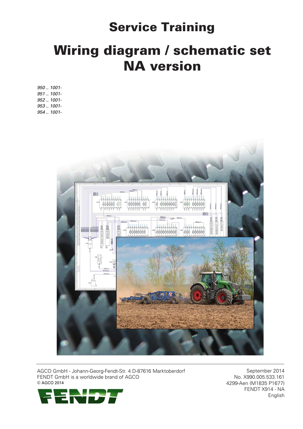
Complete North American wiring diagram and schematic set for Fendt 900 Vario S4 tractors from chassis 1001 onwards. Covers fuses, component lists, ECU pinouts, BUS systems, hydraulic circuits, compressed air systems and the full electrical architecture across 165 pages.
Description
Fendt 900 Vario S4 NA Wiring Diagram & Schematic Set
This is the full North American wiring diagram and schematic set for the Fendt 900 Vario S4 series, released under document number X990.005.533.161. It covers the 950, 951, 952, 953 and 954 chassis ranges from serial number 1001 onwards. Every electrical circuit, fuse assignment, ECU connector pinout and hydraulic schematic for the machine is laid out in this 165-page set, making it the reference document for anyone tracing faults, adding equipment or verifying factory wiring on a 900 Vario S4.
File Details
- Manual type: Wiring diagram and schematic set
- Brand: Fendt (AGCO GmbH)
- Model: 900 Vario S4
- Document number: X990.005.533.161
- Wiring diagram set number: 954.900.000.004_c_NA
- Transmission hydraulic diagram: 954.100.000.002
- TPMS wiring diagram: 954.880.200.001_b
- Version: Version 1, dated 11-09-2014
- Language: English
- Page count: 165
- File format: PDF
- Region: North America (NA)
What This Wiring Diagram Set Covers
The document is built around a numbered sheet system. Each sheet handles one electrical or hydraulic subsystem, with connector references, wire colours, separation points and component identifiers laid out in the factory notation. The set opens with the fuse assignment charts, then moves through every ECU and BUS on the machine, and closes with the hydraulic and compressed-air circuits.
Fuse Assignment and Central Electrical System
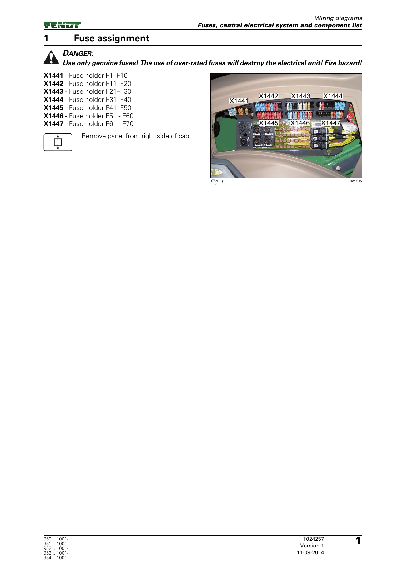
The first major block covers the fuse holders X1441 through X1447 (F1 to F70), listing pin numbers, amp ratings and the consumer each fuse protects. A separate microfuse PCB (A013) with connectors X200, X201 and X202 is documented, along with the relay block A038 and its K1 to K18 relays. This is the section you work from when a circuit is dead and you need to know which fuse or relay feeds it.
ECU and BUS Systems
Dedicated sheets cover the EXT basic control ECU (A050), the EDC engine control unit (A099), the NOx sensors (A082, A083), the AdBlue module (A084), the immobiliser (A077), the instrument panel (A007), the actuator unit (A009), the MFA multifunction armrest (A100) and the NT01/NT02 terminals (A103). Each sheet gives you the connector pinout, the signal name and the wire reference for every pin.
The BUS section breaks out the Comfort BUS, Transmission BUS, Valve BUS, ISO BUS and Engine BUS separately, with connector assignments and terminating resistances. If you are diagnosing a communication fault or adding an ISO implement, this is where the topology is documented.
Machine Systems
System-specific sheets cover the transmission control system, hydraulics and hydraulic monitoring, electrical valve supply, front and rear power lift, 4WD, differential lock and suspension, VarioGuide, power take-offs, trailer brake and brake systems, the instrument panel, all front and rear sockets, external control sockets, the 3rd and 4th hydraulic circuits, implement sockets, vehicle lighting regulations, direction indicators, headlights, work lights front and rear, reverse operation, seat and cab lighting, air conditioning, wipers, window heating, rotary beacons, radio and mirrors, and camera equipment.
Engine Management
Sheets 36 to 38 cover EDC engine control and DEUTZ engine control (including injector connectors X4146, X4147, X4360 and X4361, and the fuel dispensing unit Y091). Sheet 39 documents exhaust gas after-treatment, including the AdBlue module, the AdBlue line heaters and the CSF/SCR sensors. Sheet 40 covers VarioDoc, the GNSS aerial, VarioGuide GNSS and the tachograph.
Hydraulic and Pneumatic Circuits
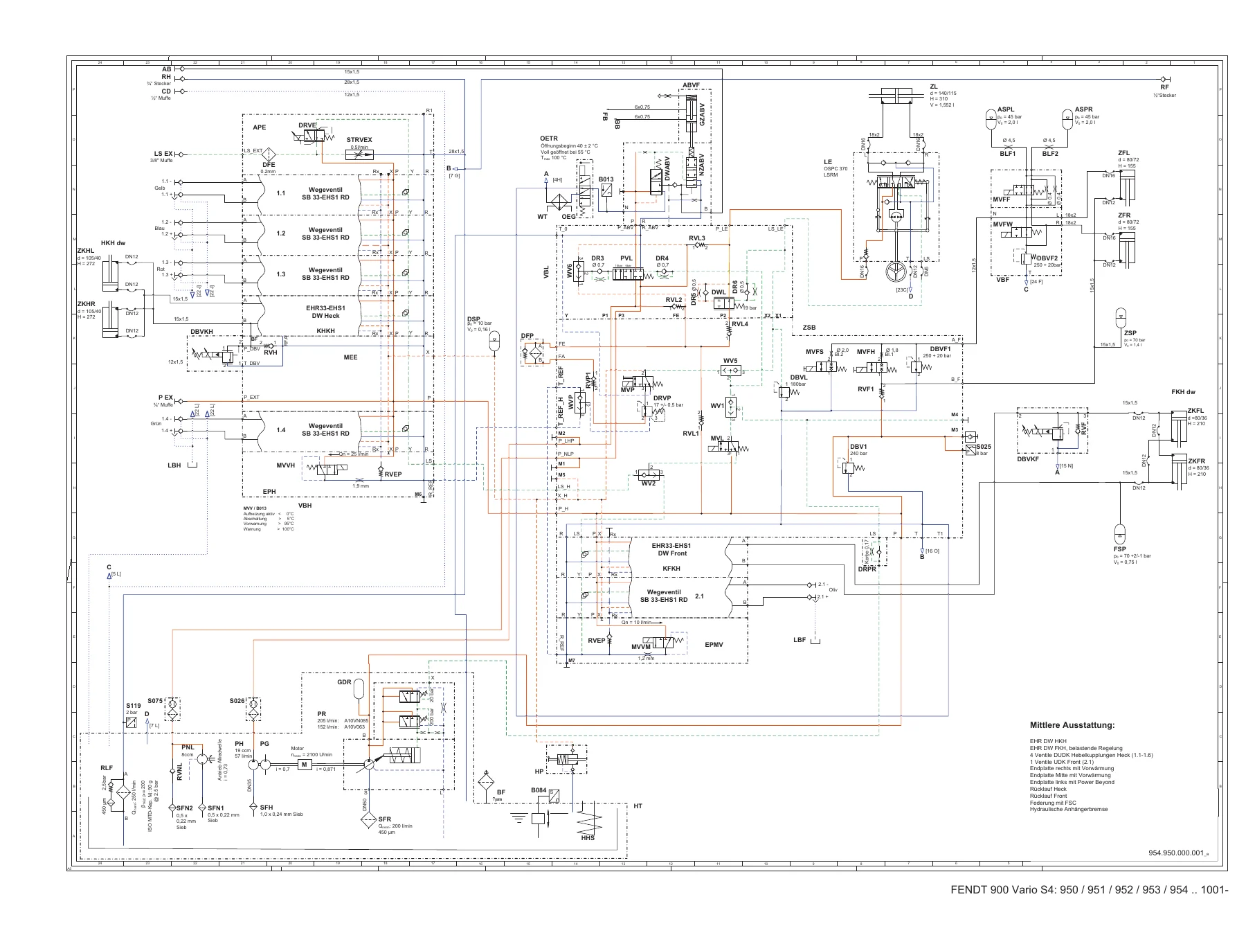
The back of the set shifts to hydraulics and compressed air. The transmission hydraulic diagram (954.100.000.002) documents the shifting circuits, drives, pumps, valves and measuring points. The compressed air section covers single-pedal single-circuit, dual-pedal single-circuit, dual-circuit and ABS dual-circuit air pressure brake diagrams, pressure supply, and the TPMS compressed air system (954.880.200.001_b). The hydraulic equipment section covers maximum, medium and minimum valve configurations plus the VarioGuide hydraulic circuit and individual valve sections.
Component List and Reserve Cables
A full DIN component list spans pages 11 to 32, giving the abbreviation, description, separation point and circuit diagram sheet number for every component on the machine. The reserve cable sheet (41) and the tractor version with ABS sheet (42) close the electrical section.
Who This Wiring Diagram Set Is For
This is a working document for technicians, electricians and owners who need the factory circuit layout rather than a generic wiring guide. Because the set is tied to a specific chassis range (950 to 954, from 1001 onwards), it stays accurate for the machines it covers. If you are chasing an intermittent fault, adding a third-party implement to the ISO BUS, verifying a repair after a harness swap, or rebuilding a damaged section of the loom, the sheet you need is in here.
The fuse assignment tables alone save hours of guesswork. The ECU pinout sheets let you back-probe a connector with confidence. The hydraulic and compressed-air schematics let you trace a circuit from the pump or compressor through to the actuator without pulling the machine apart.
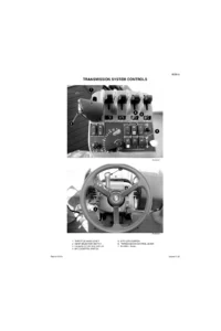
IMAGES PREVIEW
Instant PDF Delivery
The set is delivered as an instant PDF download after payment. There is no shipping, no waiting for a disc, and no regional restriction on the file itself. You can open it on a laptop in the workshop, on a tablet next to the machine, or print the specific sheets you need and take them into the cab. Search, zoom and print from any PDF reader.

Reviews
There are no reviews yet.