

GE Giraffe OmniBed Service Manual Rev 106 – 6600-0343-000 PDF Repair & Troubleshooting Guide
Original price was: $39.95.$24.95Current price is: $24.95.
Complete 283-page GE Healthcare Giraffe OmniBed service manual, document 6600-0343-000 Revision 106. Covers functional description, pre-use checkout, calibration, alarm and error code troubleshooting, rail and canopy repair, humidifier and Servo Controlled Oxygen service, plus illustrated parts, exploded views and wiring diagrams.
Description
GE Giraffe OmniBed Service Manual Rev 106 is the full technical service documentation for the GE Healthcare Giraffe OmniBed infant incubator and radiant warmer, issued under document number 6600-0343-000 at Revision 106. This 283-page PDF is written for authorized service personnel and takes a technician from system theory all the way through to component-level repair, calibration and parts identification. Every major subsystem of the OmniBed is addressed: the control board, relay board, display driver board and EL display, LED board, power supply, peripheral components, the DataLink option, the Servo Controlled Oxygen option and the humidifier assembly.
File Details
- Manual type: Service Manual
- Brand / manufacturer: GE Healthcare (Datex-Ohmeda, Inc.)
- Model: Giraffe OmniBed
- Document number: 6600-0343-000
- Revision: 106
- Copyright date: 2001
- Language: English
- Page count: 283 pages
- File format: PDF
Chapters Covered
The manual is organized into six numbered chapters plus four appendices, with a detailed table of contents and a full figure list:
- Chapter 1: Functional Description – Control Board, Relay Board, Display Driver Board / EL Display, LED Board, Power Supply, Peripheral Components, Rail and Heater Door Switches, DataLink Option, Servo Controlled Oxygen Option, Humidifier
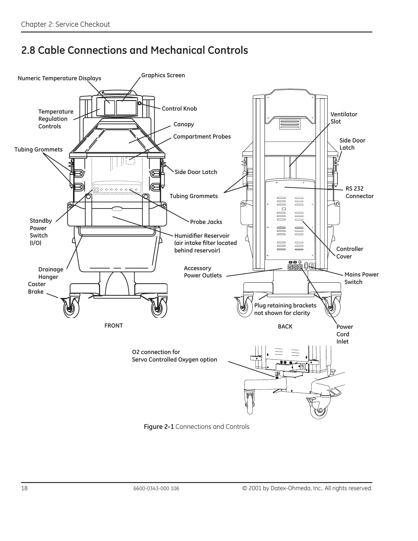
- Chapter 2: Pre-use Checkout – Setup, Mechanical Checks, Controller Checks, Humidity Check, Servo Controlled Oxygen Check (Leak Check, Pre-use Checkout, Supply Valve Leak Test), Scale Check (Mechanical Check, Center and Off Center Weight Checks), Other Accessory Checks, Cable Connections and Mechanical Controls
- Chapter 3: Calibration and Maintenance – Service Maintenance Schedule, Special Tools, System Calibration, Line Voltage Calibration, Humidifier Calibration, Servo Controlled Oxygen Calibration, Scale Calibration, Leakage Current, Ground Resistance Check
- Chapter 4: Troubleshooting – Startup Sequence, Service Screen, Alarm Messages, Error Codes, Troubleshooting Symptoms, Additional Troubleshooting Tips, Servo Controlled Oxygen service screens and alarm messages
- Chapter 5: Repair Procedures – Canopy Removal and Seal Servicing, Porthole Door Replacement, Right and Left Rail Assembly Repairs, Radiant Heater Assembly Repairs, Compartment Air Probe Repairs, Lower Unit Repairs, Bed Tilt Brake Pad, Caster Replacement, Humidifier Assembly Repairs, Controller and Display Module Procedures, Servo Controlled Oxygen Service Procedures
- Chapter 6: Illustrated Parts – Exploded Views, Accessories, Labels, PCB Layouts, Wiring Diagrams
- Appendix A: Compartment and Skin Probe Characteristics
- Appendix B: Specifications (power, outlets, standards, environment, performance, weight scale, mechanical)
- Appendix C: RS-232 Serial Data (connector, data stream, nurse call)
- Appendix D: Additional Safety Information
What that structure gives a technician is a closed loop. Chapter 1 explains how each board and subsystem is supposed to behave, so a fault can be reasoned about rather than guessed at. Chapter 2 provides the checkout sequence that must be completed before the unit goes back into clinical use. Chapter 3 defines the calibration routines that keep temperature, humidity, oxygen and weight readings trustworthy. Chapter 4 turns symptoms into answers through alarm tables, numbered system failure codes and measured-value reference points. Chapter 5 is the physical work – removing the uprights, replacing drive belts and buoyancy springs, swapping heater cartridges and thermostats, rebuilding the humidifier. Chapter 6 then identifies every part by number and shows where it sits in the assembly.
Troubleshooting, Alarm and Error Code Coverage
A large part of the troubleshooting chapter is devoted to interpreting what the OmniBed is telling you. The manual documents the full startup sequence for both user mode and service mode, then explains how to read the service screens, including the diagnostic values shown down the right-hand side such as ADT, ACT, P11, P12, P21, P22, HSP, LV1, LV2, LF, MC, TV, 5V, VR and DV, with the expected reading for each.
Alarm messages are covered individually with cause and action tables. These include Air Probe Failure, Air Temp >38C and Air Temp >40C, Baby Hot and Baby Cold, Baby Mode Disabled, Baby Probe 1 and 2 Failure, Bad Membrane Switch, Bed Heater Failure, Bed Up/Down Pedal Failure, Canopy Pedal alarms, Fan Always in High Speed, Fan Failure, Heater Doors Not Closed and Not Opened, Humidifier Failure, In Transition – Heat Off, Motor Drive Failure, Power Failure, Radiant Heater Failure, Temperature out of Calibration, and the pedal pressed alarms. System failure codes 0 through 99 are each broken out with their meaning, likely cause and the order in which corrective actions should be attempted. Separate Servo Controlled Oxygen alarm tables cover Low Oxygen, High Oxygen, Oxygen Probe Failure, O2 Cal Lost, Oxygen System Failure 1 and 2, Calibration Failed and FiO2 >26%.
The Additional Troubleshooting Tips section then explains how to actually take the measurements referenced in those charts – checking incubator heater and bed safety thermostat resistance, radiant heater resistance, power supply voltages at the 4-pin bus connectors, switch and thermostat continuity at the relay board connectors, humidifier heater and safety thermostat values, compartment air probe and patient probe thermistor readings, heat sink sensor resistance versus temperature, and how to diagnose the E-base and canopy motors, a failed rail lift belt, the 50 pin ribbon cable and the toroidal transformer.
Repair Procedures for the Whole Machine
The repair chapter is detailed enough to support real workshop work. Canopy removal is covered along with both the original and enhanced canopy seal servicing, and the porthole door replacement. The right upright (motor side) and left upright can each be removed, and the manual walks through the internal rail repairs: removing the inner rail assembly, replacing rollers and tension springs, separating the lift rail from the belt channel, replacing the rail drive belt, replacing rail buoyancy springs, and replacing the slip clutch or motor roll pin. On the left side it covers the cable carrier links and the heater wire harness / cable carrier assembly replacement in step order, including the 3-pin MAT-N-LOK connector work.
Radiant heater work includes removing the canopy/heater assembly, realigning the canopy, replacing the radiant heater element, the heater door spool assembly, heater door cable adjustment and spring tube assembly replacement. Lower unit procedures cover the incubator fan, fan motor and optical fan sensor, both incubator heater cartridges, the elevating base, chassis replacement, bed up/down and canopy pedal switches, the canopy membrane switch, bed tilt brake pad, casters, and full humidifier disassembly and reassembly. Controller and display module procedures cover the display driver board, EL display, rotary encoder, LED board, membrane switch panel, probe panel and battery, plus the control board, relay board, solid state relays, power supply and toroidal transformer.
Illustrated Parts, PCB Layouts and Wiring Diagrams
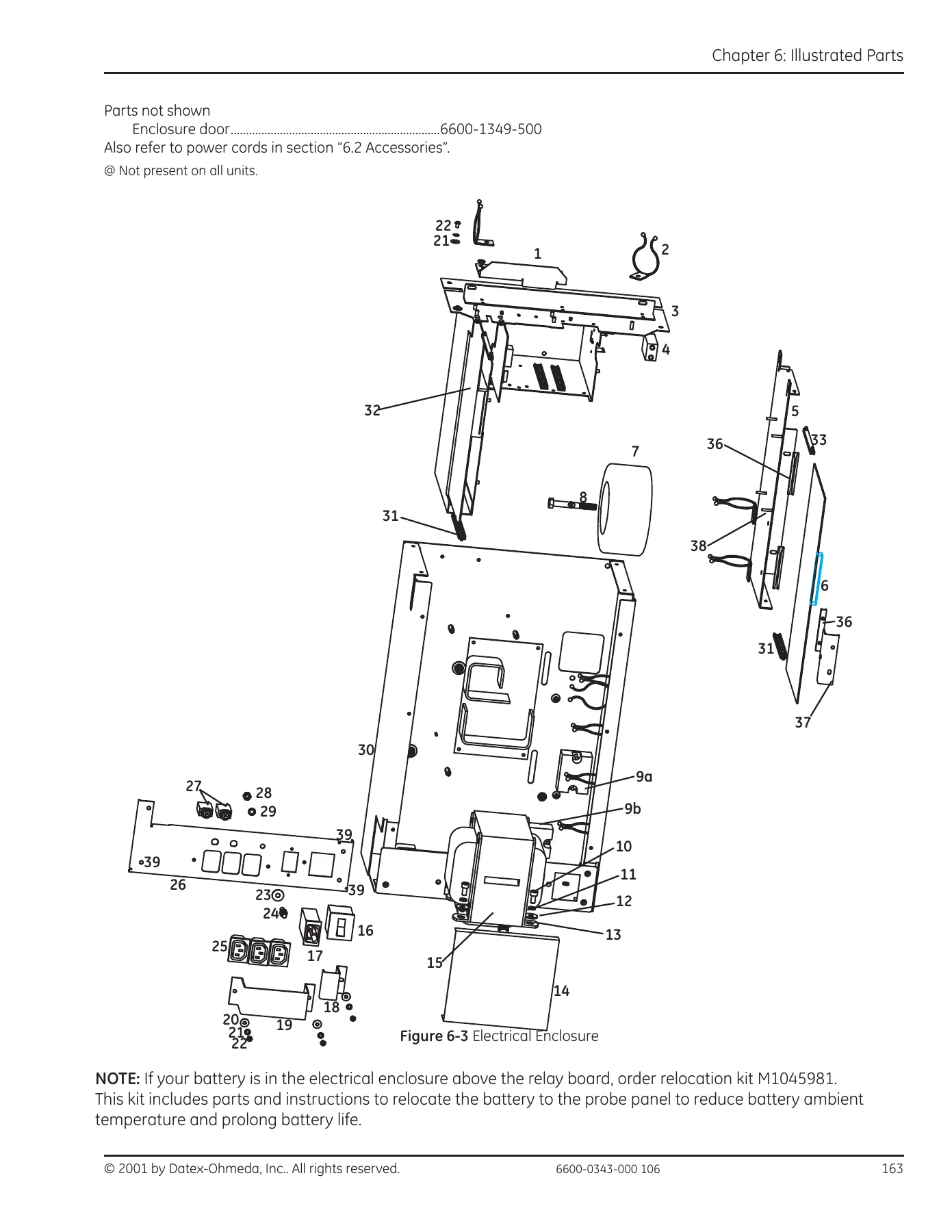
Chapter 6 is a genuine parts reference. Exploded views and parts lists cover the probe housing, display module and electrical enclosure; the bed and side panels; the radiant heater and canopy including original and enhanced canopy seal parts; the chassis; the humidifier; both old and current elevating base designs; the uprights and lift rail components; the compartment air probe; Servo Control Oxygen components; the storage drawer; and the accessory range from instrument and monitor shelves to the E-cylinder holder, tubing management arm, dovetail mounts, silo support and rotating IV pole. Labels are listed by part number, PCB layouts are provided for the control board, display driver board and both relay board revisions, and the wiring diagram set runs from the control board through the elevating base and canopy lift rails, electrical enclosure, graphics display, incubator relay board, radiant heater relay board, servo humidifier relay board and Servo Control Oxygen.
Specifications and Appendices
Appendix A provides compartment and skin probe temperature-to-resistance characteristics. Appendix B lists power requirements for 100V, 115V, 220V, 230V and 240V operation, accessory outlet ratings, applicable standards, operating and storage environment, user control settings, alarm thresholds, system performance, Servo Control Oxygen performance, weight scale range and accuracy, and mechanical dimensions. Appendix C documents the RS-232 connector pinout, the two-second ASCII data stream field by field, and the nurse call contact configuration and ratings. Appendix D adds safety statements and unit symbols.
Why This Giraffe OmniBed Service Manual Matters
With the GE Giraffe OmniBed Service Manual Rev 106 on hand, a technician can diagnose an alarm or system failure code instead of swapping parts blindly, perform the correct calibrations after replacing a control board or relay board, complete the pre-use checkout that clears the unit for patient use, and carry out mechanical repairs on the canopy, rails, heaters, humidifier and elevating base down to the individual spring, roller, belt and switch. The illustrated parts chapter means the right component can be identified and ordered without guesswork, and the wiring diagrams make tracing a fault through the connectors practical.
IMAGES PREVIEW
This 6600-0343-000 service manual is delivered as an instant PDF download – no shipping, no waiting. Open it on a laptop, tablet or phone in the workshop or at the bedside, print the pages you need for the job in front of you, and keep the rest of the 283-page reference ready for the next repair.

Reviews
There are no reviews yet.