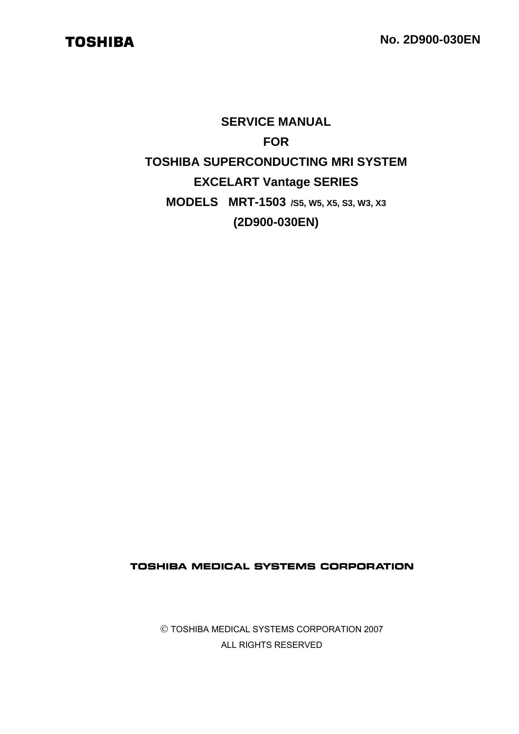
Toshiba EXCELART Vantage MRT-1503 S5 W5 X5 S3 W3 X3 MRI Service Manual 2D900-030EN – 2007
$49.95 Original price was: $49.95.$29.95Current price is: $29.95.
604-page Toshiba EXCELART Vantage MRT-1503 MRI service manual covering MRT-1503/S5, W5, X5, S3, W3 and X3 systems. Document 2D900-030EN covers controller electronics, RF cabinet and amplifier, superconducting magnet, refrigerator, gantry, patient couch, gradient power supplies, transformer cabinet, troubleshooting, adjustments and component replacement.
Description
Toshiba EXCELART Vantage MRT-1503 S5 W5 X5 S3 W3 X3 MRI Service Manual 2D900-030EN – 2007
The Toshiba EXCELART Vantage MRT-1503 S5 W5 X5 S3 W3 X3 MRI Service Manual 2D900-030EN – 2007 is a detailed service reference for the EXCELART Vantage series superconducting MRI system models MRT-1503/S5, MRT-1503/W5, MRT-1503/X5, MRT-1503/S3, MRT-1503/W3, and MRT-1503/X3. Its coverage runs from magnetic-field safety and operating environment requirements through controller electronics, RF generation and reception, the superconducting magnet and refrigerator, gantry hardware, patient couch mechanisms, gradient power supplies, transformer cabinet equipment, and the optional shim coil amplifier. The manual is organized around service work, with system block diagrams, board settings, LED indications, wiring and connection information, troubleshooting sections, replacement procedures, adjustments, service parts references, and operational checks.
System and Service Scope
This Toshiba EXCELART Vantage MRT-1503 service manual begins with the precautions required when working around an energized superconducting magnet. It addresses magnetic medical prostheses, metallic accessories, tools and measuring instruments, access control in the MRI room, emergency action during a quench, very low-temperature cryogen hazards, and precautions specific to the short-axis magnet used in MRT-1503 systems. The system chapter then identifies the main equipment configuration: gantry, patient couch, wall cabinet, controller, RF cabinet, gradient power supply and control cabinet, refrigerator, transformer cabinet, supervisory unit, QD whole-body RF coil, cables, and accessories.
Technical reference material in the early system section gives the service engineer important operating and interface data. The magnet is identified as a 1.5-tesla superconducting type with a 655 mm aperture and liquid helium cryogen. The manual distinguishes gradient performance between the S5/W5/X5 group and the S3/W3/X3 group, and it documents RF transmission data, magnet-bore dimensions, room temperature and humidity requirements, power supply requirements, and patient couch dimensions, positioning accuracy, and maximum load. It also lists compatible RF coils and optional units used with the system, helping the reader understand how the base configuration can be equipped.
Controller, RF and Signal-Path Service
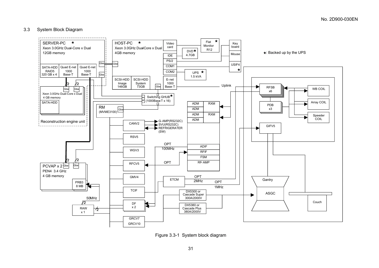
A major portion of the Toshiba EXCELART Vantage MRT-1503 S5 W5 X5 S3 W3 X3 MRI Service Manual 2D900-030EN – 2007 is devoted to the controller and its electronics. The controller coverage identifies the G-CONT, power, RM, ETCM, Gigabit Ethernet hub, FEP-PC/PC-VAP, reconstruction engine, UPS, CPU cabinet, control box, control pad, monitor, keyboard, mouse, and related operator-room equipment. Detailed board sections explain the RM, RSV5, WGV3, RFCV5, GRC, CANV2, TCIF, RAW, DF, and ETCM boards, including functions, switch settings, connectors, standard configurations, and LED indications. Cable diagrams show 100-VAC distribution, signal links, network connections, and internal controller wiring.
The replacement chapter goes beyond identification and includes component access and service procedures for the control cabinet, server PC, and CPU cabinet. It covers items such as hard disks, memory modules, network and RAID cards, graphics hardware, power supplies, and drives, with photographs and location drawings that help relate the written procedure to the actual cabinet hardware.
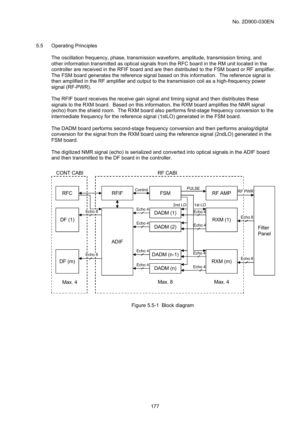
The RF cabinet section follows the signal path through the RF unit and RF amplifier. It covers the RF chassis, RXM chassis, RFIF, ADIF, FSM, DADM and RXM boards, DC power supplies, board settings, LED indications, analog signal I/O, adjustment terminals, internal wiring, and optical signal connections. Maintenance procedures include RF amplifier replacement, RF cabinet relocation, RF chassis access, PWB replacement, PS1 and PS2 replacement, and power-supply output adjustment. A separate RF amplifier subsection describes composition, ratings, operation, MRI-system connection, methods for locating faulty sections, and replacement.
Magnet, Gantry and Patient Couch Coverage
The magnet system chapter is built around the service risks and procedures unique to superconducting MRI equipment. It provides precautions for very low-temperature cryogen and the superconducting magnet, then covers the magnet structure, quench conditions, rupture-disk replacement, quench-valve leak checks, quench vent-line checks, abnormal helium boil-off, shield-temperature measurement, O-ring handling, and liquid-helium refilling guidance. The Magnet Supervisory Unit section includes functions, operation, replacement, circuit diagrams, and spares. The APD refrigerator material addresses structure, couplings, charging and venting, status displays, troubleshooting, and compressor internal wiring.
Gantry coverage identifies ferromagnetic-material locations, warning labels, cable connections, the magnet-bore light, flow switch, cover removal, and vacuum-chamber removal. The SIDE-RF system and QD whole-body coil sections add board-level and RF-coil troubleshooting material. The patient couch chapter explains operating principles for vertical and horizontal movement, the mechanical structure, cover removal, hydraulic-cylinder replacement, pump-unit oil-level adjustment, UP/DOWN limit switching, couch-height adjustment, horizontal travel limits, guide-roller adjustment, and port pin assignments.
IMAGES PREVIEW
Gradient Power, Transformer and Shim Systems
The gradient power supply chapter covers both CASCADE-type and DX-type systems. It identifies the applicable power-supply types, ratings and service tools, then works through boards, block and connection diagrams, error finding, part replacement, and service parts. The CASCADE material includes the GSSU and its D11/D112 DAC, D12 regulator, D14 modulator, D16 CAN/Service, and D17 I/O boards. The DX section covers the GCU boards, inrush control and rectifier boards before moving into its troubleshooting and replacement procedures. These sections are particularly useful when a service task requires tracing a gradient-system fault from control signals through the high-power hardware rather than treating the power supply as a single replaceable unit.
The transformer cabinet chapter explains the system transformer and the optional vacuum pump unit that maintains vacuum in the gantry vacuum chambers. It includes external views, connection information, vacuum-pump structure and operation, diaphragm and bearing replacement, pressure switch and timer material, and a troubleshooting list. The optional shim coil amplifier chapter closes the technical coverage with requirements for use, ratings, operating principles, AMP module and interface-board details, power circuitry, cables, troubleshooting, abnormal-image symptoms associated with shim amplifier faults, temporary countermeasures, part replacement, and operational checks.
File Details
- Manual type: Service Manual
- Brand: Toshiba
- Series: EXCELART Vantage
- Models: MRT-1503/S5, MRT-1503/W5, MRT-1503/X5, MRT-1503/S3, MRT-1503/W3, MRT-1503/X3
- Document number: 2D900-030EN
- Initial revision: 02/’07
- Language: English
- Pages: 604
- File format: PDF
Chapters Covered
- 1. SCOPE
- Precautions Related to the Magnetic Field
- 2. OPERATING ENVIRONMENT
- Power Voltage
- Operating Temperature and Humidity
- 3. SYSTEM
- Standard Configuration
- Combinable Units (optional)
- System Block Diagram
- Classification of Equipment
- Influence on Peripheral Units
- Cleaning
- 4. CONTROLLER
- Descriptions and Locations of Warning Labels
- External View and Configuration
- Controller Cable Connections
- Settings of the Switches on the Boards and the Units and Descriptions of the LEDs
- Replacement Procedures
- 5. RF CABINET
- Overview
- Warning Labels on the RF Cabinet
- Fuses and Breakers (NFBs)
- Precautions Regarding the RF Cabinet
- Operating Principles
- Composition of the RF Unit
- Internal Wiring
- External Connections (Optical Signals)
- Maintenance and Replacement Procedures
- RF Amplifier
- 6. WALL CABINET
- Outline
- GIF V5 Board
- Troubleshooting for the Patient Couch and Gantry System
- 7. MAGNET SYSTEM
- Overview
- Superconducting Magnet
- Magnet Supervisory Unit (MSU)
- APD Refrigerator
- 8. UNITS OF THE GANTRY
- Locations of Ferromagnetic Materials
- Warning and Caution Labels
- Cable Connections in the Gantry
- Light in the Magnet Bore
- Flow Switch
- Removing the Gantry Covers
- Removing the Vacuum Chambers
- SIDE-RF System
- QD Whole-Body Coil
Complete PDF Bookmark TreeComplete Bookmarks
The complete bookmarks in the “Toshiba EXCELART Vantage MRT-1503 S5 W5 X5 S3 W3 X3 MRI Service Manual 2D900-030EN – 2007” are as follows:
Safety Precautionsp. 4+1. SCOPEp. 14
+1.1 Precautions Related to the Magnetic Fieldp. 15
1.1.1 Magnetic medical prosthesesp. 161.1.2 Metallic accessoriesp. 181.1.3 Metallic tools, appliances, and measuring instrumentsp. 191.1.4 Countermeasures against emergencies in the MRI room (superconducting MRI system)p. 211.1.5 Precautions for the short-axis magnetp. 221.1.6 Other precautionsp. 22+2. OPERATING ENVIRONMENTp. 27
2.1 Power Voltagep. 272.2 Operating Temperature and Humidityp. 27+3. SYSTEMp. 29
3.1 Standard Configurationp. 293.2 Combinable Units (optional)p. 303.3 System Block Diagramp. 313.4 Classification of Equipmentp. 32+3.5 Influence on Peripheral Unitsp. 32
3.5.1 Data on the magnetp. 323.5.2 Data on the gradient fieldp. 353.5.3 Data on the radio frequency (RF) emissionp. 353.5.4 Data on the magnet borep. 353.5.5 Data on the patient couchp. 353.6 Cleaningp. 36+4. CONTROLLERp. 37
4.1 Descriptions and Locations of Warning Labelsp. 37+4.2 External View and Configurationp. 38
4.2.1 G-CONT unitp. 424.2.2 Power unitp. 424.2.3 RM unitp. 434.2.4 ETCM unitp. 454.2.5 Hub unit (for Gigabit Ethernet)p. 464.2.6 FEP-PC unit (PC VAP unit)p. 46+4.2.7 Reconstruction engine unitp. 47
4.2.7.1 AP-PC unitp. 474.2.7.2 Server PC unitp. 474.2.8 UPS (uninterruptible power supply) unitp. 484.2.9 Operator room unitp. 494.3 Controller Cable Connectionsp. 54+4.4 Settings of the Switches on the Boards and the Units and Descriptions of the LEDsp. 59
4.4.1 RM boardp. 594.4.2 RSV5 boardp. 604.4.3 WGV3 boardp. 654.4.4 RFCV5 boardp. 714.4.5 GRC boardp. 754.4.6 CANV2 boardp. 924.4.7 TCIF boardp. 954.4.8 RAW boardp. 964.4.9 DF boardp. 994.4.10 ETCM boardp. 1044.4.11 Gigabit Ethernet hub unitp. 109+4.4.12 FEP-PC unit (PC-VAP unit)p. 111
4.4.12.1 PRB3 boardp. 120+4.4.13 UPS (uninterruptible power supply) unitp. 122
4.4.13.1 Overviewp. 1244.4.13.2 External dimensions and part namesp. 1254.4.13.3 Operation (normal start)p. 1294.4.13.4 Basic operationp. 1314.4.13.5 Protective functionsp. 1334.4.13.6 Maintenance and inspectionp. 1364.4.14 Control boxp. 1394.4.15 LCD monitorp. 144+4.5 Replacement Proceduresp. 147
4.5.1 Replacement of components in the control cabinetp. 1484.5.2 Procedure for replacing the service parts in the server PCp. 1494.5.3 Procedure for replacing the service parts in the CPU cabinetp. 155+5. RF CABINETp. 163
5.1 Overviewp. 1635.2 Warning Labels on the RF Cabinetp. 1665.3 Fuses and Breakers (NFBs)p. 1755.4 Precautions Regarding the RF Cabinetp. 1765.5 Operating Principlesp. 177+5.6 Composition of the RF Unitp. 178
5.6.1 Slot composition of the RF chassis and the RXM chassisp. 1785.6.2 RFIF board and ADIF boardp. 1805.6.3 FSM boardp. 1815.6.4 DADM boardp. 1815.6.5 RXM board (in the RXM chassis)p. 1815.6.6 DC power supply units in the RF unitp. 1825.6.7 Board settingsp. 1885.6.8 LED indicationsp. 1975.6.9 Analog signal I/Op. 2005.6.10 Adjustment terminalsp. 2005.6.11 RF unit errorsp. 2015.7 Internal Wiringp. 2025.8 External Connections (Optical Signals)p. 208+5.9 Maintenance and Replacement Proceduresp. 209
5.9.1 RF Amplifier Replacementp. 2095.9.2 Replacement or relocation of the RF cabinetp. 2125.9.3 Pulling out the RF chassisp. 2155.9.4 Replacement of PWBs inside the RF chassisp. 2165.9.5 Replacement of PWBs inside the RXB chassisp. 217+5.9.6 Replacement of the PS1 unitp. 218
5.9.6.1 Removing the PS1 unitp. 2185.9.6.2 Installing the new PS1 unitp. 218+5.9.7 Replacement of the PS2 unitp. 218
5.9.7.1 Removing the PS2 unitp. 2185.9.7.2 Installing the new PS2 unitp. 2185.9.8 Adjustment of the PS1 output voltagesp. 2195.9.9 Adjustment of the PS2 output voltagesp. 220+5.10 RF Amplifierp. 221
5.10.1 Outlinep. 2215.10.2 Compositionp. 2225.10.3 Power ratingsp. 2235.10.4 Amplifier operationp. 223+5.10.5 Connection with the MRI systemp. 224
5.10.5.1 Outlinep. 2245.10.5.2 System I/F cablep. 2255.10.5.3 BNC connector (Refer to figure 5.10-2.)p. 2255.10.5.4 HN connector (Refer to figure 5.10-2.)p. 225+5.10.6 Methods for finding faulty sectionsp. 226
5.10.6.1 If an error occursp. 2265.10.6.2 Error occurrence status display and LED status displayp. 2265.10.7 Replacementp. 226+6. WALL CABINETp. 227
6.1 Outlinep. 2276.2 GIF V5 Boardp. 2326.3 Troubleshooting for the Patient Couch and Gantry Systemp. 237+7. MAGNET SYSTEMp. 239
+7.1 Overviewp. 239
7.1.1 General precautionsp. 2397.1.2 Precautions for handling the very low-temperature cryogenp. 241+7.1.3 Precautions for handling the superconducting magnetp. 243
7.1.3.1 Emergency helium discharge pipe system and ventilationp. 2437.1.3.2 Precautions against vacuum failurep. 2467.1.3.3 Precautions at the time of maintenancep. 2467.1.3.4 Other precautions for handling the unitsp. 247+7.2 Superconducting Magnetp. 248
7.2.1 Safety labelsp. 2487.2.2 Outline drawingp. 2547.2.3 Description of each partp. 2557.2.4 Quenchp. 256+7.2.5 Replacement of the rupture diskp. 260
7.2.5.1 Replacing the main rupture diskp. 2607.2.5.2 Replacing the auxiliary rupture diskp. 2627.2.5.3 Checking the integrity of the service turret and the valve sealp. 2627.2.6 Leak check for the quench valvep. 2637.2.7 Checking the quench vent line blanking flangep. 2637.2.8 Abnormal level of helium boil-offp. 2647.2.9 Measuring the shield temperaturep. 2667.2.10 Handling of the O-ringp. 2697.2.11 Hints and tips for LHe refillingp. 269+7.3 Magnet Supervisory Unit (MSU)p. 272
+7.3.1 Functions and operationp. 272
7.3.1.1 D1 module (monitor)p. 2737.3.1.2 D2 module (He, EIS, and battery)p. 2757.3.1.3 D3 module (ERDU)p. 2787.3.1.4 D4 module (processor)p. 280+7.3.2 MSU replacement procedurep. 282
7.3.2.1 Boards D1 to D4p. 2837.3.2.2 Removing the DC power modulep. 2847.3.2.3 Replacing the DC power supply unit and battery packp. 2867.3.2.4 Replacing an external batteryp. 2887.3.3 Circuit diagramsp. 2907.3.4 Sparesp. 303+7.4 APD Refrigeratorp. 304
7.4.1 Precautions of the APD refrigeratorp. 3047.4.2 Definition of symbols used in this subsection and on the refrigeratorp. 3077.4.3 Safety labelsp. 3087.4.4 Appearance and structure of the refrigeratorp. 3097.4.5 Handling of Aeroquip couplingsp. 3107.4.6 Charging or ventingp. 3117.4.7 System status displayp. 315+7.4.8 Troubleshootingp. 316
7.4.8.1 Error conditionsp. 3177.4.8.2 Clearing error conditionsp. 3187.4.8.3 Restarting after an error conditionp. 3187.4.8.4 Troubleshooting guidep. 3197.4.9 Compressor internal wiringp. 321+8. UNITS OF THE GANTRYp. 323
8.1 Locations of Ferromagnetic Materialsp. 3238.2 Warning and Caution Labelsp. 3258.3 Cable Connections in the Gantryp. 3288.4 Light in the Magnet Borep. 3288.5 Flow Switchp. 3298.6 Removing the Gantry Coversp. 3308.7 Removing the Vacuum Chambersp. 336+8.8 SIDE-RF Systemp. 337
8.8.1 Generalp. 3378.8.2 Troubleshooting related to the SIDE-RF systemp. 3418.8.3 RFSB boardp. 3418.8.4 GETB boardp. 343+8.9 QD Whole-Body Coilp. 344
8.9.1 Outlinep. 3458.9.2 Bobbin and tuning sectionp. 3468.9.3 Circuit sectionp. 3478.9.4 Troubleshooting for the RF coil systemp. 348+9. PATIENT COUCHp. 350
9.1 Overviewp. 3509.2 Sections Where Magnetic Parts Are Usedp. 351+9.3 Principles of Operationp. 352
9.3.1 Couch controlp. 3529.3.2 Vertical movement drive of the patient couchp. 3569.3.3 Couchtop horizontal movement drivep. 358+9.4 Structural Description of the Couch Main Bodyp. 359
9.4.1 Couchtop horizontal movement drivep. 3649.4.2 Couchtopp. 3659.4.3 Vertical movement mechanical controlp. 3669.4.4 Vertical movement drive sectionp. 367+9.5 Mounting and Removing the Coversp. 368
9.5.1 Outline of workp. 3689.5.2 Detailed work proceduresp. 368+9.6 Replacement and Adjustment of Partsp. 374
9.6.1 Replacing the hydraulic cylinder as a whole setp. 3749.6.2 Oil level adjustment of the pump unitp. 3779.6.3 UP and DOWN limit switching and couch height adjustment (see figures 9.6-3, 9.6-4, and 9.6-5)p. 3779.6.4 Couchtop horizontal movement limit switching and adjustment (see figures 9.6-6 and 9.6-7)p. 3809.6.5 Adjustment of the couchtop guide rollerp. 3829.7 Pin Assignment of Each Portp. 383+10. GRADIENT POWER SUPPLYp. 390
+10.1 Outlinep. 391
10.1.1 Types of gradient power supply and ratingsp. 39110.1.2 Differences between the KL and TELI gradient power suppliesp. 39210.1.3 Types of KL gradient power supplies and differences between themp. 39310.1.4 Types of TELI gradient power supplies and differences between themp. 39410.1.5 Tools required for servicingp. 39410.1.6 Reference: Temperature, humidity, and condensationp. 395+10.2 CASCADE-Type Gradient Power Supplyp. 397
10.2.1 Caution labelsp. 39710.2.2 Name and function of each sectionp. 39910.2.3 Block diagram and connection diagramp. 40510.2.4 D11 (or D112) DAC board in the GSSUp. 40710.2.5 D12 REGULATOR board in the GSSUp. 40910.2.6 D14 MODULATOR board in the GSSUp. 41410.2.7 D16 CAN/Service board in the GSSUp. 41710.2.8 D17 I/O board in the GSSUp. 420+10.2.9 Troubleshootingp. 423
10.2.9.1 D12 REGULATOR boardp. 42410.2.9.2 D14 MODULATOR boardp. 42710.2.9.3 D17 I/O boardp. 43510.2.9.4 Failure of the power stagep. 43510.2.9.5 Failure of the soft-start circuitp. 43810.2.9.6 The gradient power supply cannot be turned ONp. 439+10.2.10 Part replacement proceduresp. 440
10.2.10.1 Boards in the GSSU (Gradient Small Signal Unit)p. 44010.2.10.2 Current sensor unitp. 44310.2.10.3 Power stagesp. 44610.2.10.4 D32 rectifier boardp. 45010.2.10.5 D31 soft-start boardp. 45210.2.10.6 Fan (below the power stages)p. 45310.2.10.7 Choke coilp. 45410.2.10.8 AC line filterp. 45510.2.10.9 Manifold (water distributor) and manifold couplersp. 45610.2.10.10 Soft-start contactorp. 45710.2.10.11 Separating the gradient power supply from the control cabinetp. 45910.2.11 Service partsp. 463+10.3 DX-Type Gradient Power Supplyp. 468
10.3.1 Caution labelsp. 46810.3.2 Name and function of each sectionp. 47010.3.3 Block diagram and connection diagramp. 47610.3.4 DACG1 board in the control board chassis (GCU)p. 48010.3.5 PWMG1 board in the control board chassis (GCU)p. 48310.3.6 COBG1 board in the control board chassis (GCU)p. 48510.3.7 Inrush control boardp. 49410.3.8 Rectifier boardsp. 49610.3.9 Troubleshootingp. 497+10.3.10 Part replacement proceduresp. 509
10.3.10.1 Boards in the control board chassisp. 50911.3.10.2 Current sensor unitp. 51210.3.10.3 Power stagesp. 51510.3.10.4 Rectifier board unitp. 51910.3.10.5 Inrush control boardp. 52110.3.10.6 Fan (below the power stages)p. 52210.3.10.7 Choke coilp. 52310.3.10.8 AC line filterp. 52410.3.10.9 Manifold (water distributor) and manifold couplersp. 52510.3.10.10 Soft-start contactorp. 52610.3.10.11 Low-voltage fusesp. 52710.3.10.12 DC power supplyp. 52810.3.10.13 Separating the gradient power supply from the control cabinetp. 53110.3.11 Service partsp. 534+11. TRANSFORMER CABINETp. 540
11.1 Outlinep. 54011.2 External Viewsp. 54111.3 System Transformerp. 543+11.4 Vacuum Pump Unit (Option)p. 545
11.4.1 Precautions for handling the vacuum pump unitp. 54511.4.2 Structure of the vacuum pump unitp. 54511.4.3 Function of each partp. 54811.4.4 Vacuum pump operating procedurep. 54811.4.5 Structure of the vacuum pumpp. 55011.4.6 Replacing the diaphragms in the vacuum pumpp. 55011.4.7 Replacing the bearings in the vacuum pumpp. 550+11.4.8 Procedure for replacing the diaphragms and associated componentsp. 551
11.4.8.1 Replacing the diaphragmsp. 55211.4.8.2 Replacing the valvesp. 55511.4.8.3 Replacing the non-return valvesp. 55711.4.8.4 Replacing the O-ringsp. 55811.4.8.5 Replacing the head gasketsp. 559+11.4.9 Pressure switchp. 560
11.4.9.1 Set value checking procedurep. 56111.4.9.2 Unit selection procedurep. 56211.4.9.3 Zero adjustment procedurep. 56411.4.9.4 Switch functionsp. 56511.4.10 Timerp. 56811.4.11 Troubleshooting listp. 569+12. SHIM COIL AMPLIFIER (OPTION)p. 571
12.1 Outlinep. 57112.2 Requirements for Usep. 57112.3 Ratingsp. 57112.4 Compositionp. 57212.5 Operating Principlesp. 572+12.6 Operations of Each Sectionp. 573
+12.6.1 Basic operations of the shim coil amplifierp. 573
12.6.1.1 Outlinep. 57312.6.1.2 Turning ON the power of the shim coil amplifierp. 573+12.6.2 AMP module (figure 12.6-4)p. 580
12.6.2.1 Front panel (figure 12.6-6)p. 58012.6.2.2 GAIN STAGE PWB (figure 12.6-4)p. 581+12.6.3 SHIMD IF PWB tray (figure 12.6-5)p. 581
12.6.3.1 Tray (figure 12.6-7)p. 58112.6.3.2 SHIMD IF PWB (figure 12.6-5)p. 58212.6.4 POWER PWB (figure 12.6-8)p. 58312.6.5 Power supply section (figure 12.6-9)p. 584+12.6.6 Connection cablesp. 585
12.6.6.1 Interconnecting cables and connecting sectionsp. 58512.6.6.2 Function of each interconnecting cablep. 58512.6.6.3 Signal cables within the chassis and their functions (figure 12.6-10)p. 586+12.7 Troubleshootingp. 588
12.7.1 Precautions during troubleshootingp. 58812.7.2 Troubleshooting proceduresp. 58812.7.3 Meanings of LEDsp. 589+12.7.4 Details of troubleshootingp. 590
12.7.4.1 AMP modulep. 59012.7.4.1.1 When the HV READY LED on every AMP module is not lit (figure 12.6-6) (No HV FLT LED on the AMP modules is lit)p. 59012.7.4.1.2 When the HV FLT LED is lit (figures 12.6-2, 12.6-4, and 12.6-6)p. 59012.7.4.1.3 When the 15V READY LED is not lit (figures 12.6-2 and 12.6-6) (15V READY LED on the SHIMD IF PWB is lit)p. 59012.7.4.1.4 When the CURRENT ERROR LED lights (figures 12.6-2, 12.6-4, and 12.6-6)p. 59112.7.4.1.5 When the FUSE ERROR LED lights (figures 12.6-2 and 12.6-4)p. 59112.7.4.1.6 When the OVER TEMP LED lights (figures 12.6-2 and 12.6-4)p. 59112.7.4.2 SHIMD IF PWB trayp. 59212.7.4.2.1 When the HV FLT LED lights (figure 12.6-7)p. 59212.7.4.2.2 When 15V READY LED and/or 5V READY LED is not lit (figures 12.6-2, 12.6-5, and 12.6-7)p. 59212.7.4.2.3 When the ALL READY LED is not lit (figure 12.6-7)p. 59212.7.5 Abnormal image generation due to malfunctioning shim coil amplifierp. 593+12.7.6 Temporary countermeasures in case of shim coil amplifier failurep. 594
12.7.6.1 Precautionsp. 59412.7.6.2 Procedures for taking the temporary countermeasures (also refer to figure 12.6-3)p. 59412.7.6.3 Recovery procedures (also refer to figure 12.6-3)p. 595+12.8 Procedures for Parts Replacementp. 596
+12.8.1 AMP module replacement and adjustment proceduresp. 596
12.8.1.1 Tools and jigs required for replacementp. 59612.8.1.2 Replacement procedures (also refer to figures 12.6-2, 12.6-4, and 12.8-1)p. 59612.8.1.3 AMP module offset adjustment proceduresp. 59812.8.2 SHIMD IF PWB replacement procedures (also refer to figures 12.6-2 and 12.6-5)p. 598+12.9 Operational Checksp. 599
12.9.1 Starting up the unitp. 59912.9.2 Checking the output currentp. 59912.10 Caution Labelsp. 601 - 9. PATIENT COUCH
- Overview
- Sections Where Magnetic Parts Are Used
- Principles of Operation
- Structural Description of the Couch Main Body
- Mounting and Removing the Covers
- Replacement and Adjustment of Parts
- Pin Assignment of Each Port
- 10. GRADIENT POWER SUPPLY
- Outline
- CASCADE-Type Gradient Power Supply
- DX-Type Gradient Power Supply
- 11. TRANSFORMER CABINET
- Outline
- External Views
- System Transformer
- Vacuum Pump Unit (Option)
- 12. SHIM COIL AMPLIFIER (OPTION)
- Outline
- Requirements for Use
- Ratings
- Composition
- Operating Principles
- Operations of Each Section
- Troubleshooting
- Procedures for Parts Replacement
- Operational Checks
- Caution Labels
Taken as a whole, the chapter structure gives a technician a system-level path from safety and environmental checks to cabinet and board identification, signal tracing, fault isolation, mechanical access, component replacement, adjustment, and post-service operational checks. It combines system architecture with subsystem-level service detail, so the reader can move between the MRI system as a complete installation and the individual controller, RF, magnet, gantry, couch, gradient, transformer, refrigerator, and shim-amplifier assemblies involved in a repair.
Service, Diagnose and Repair with the Correct Reference
The Toshiba EXCELART Vantage MRT-1503 S5 W5 X5 S3 W3 X3 MRI Service Manual 2D900-030EN – 2007 supports a wide range of practical service work: tracing controller and RF faults, interpreting board LEDs and switch settings, checking cable and optical-signal paths, troubleshooting the patient couch and gantry, servicing magnet-support and refrigerator equipment, replacing specified electronic and mechanical components, working through gradient power-supply faults, and carrying out documented adjustments and operational checks. For equipment this complex, using the correct procedures, connection diagrams, settings, safety precautions, and model-specific specifications matters when diagnosing a fault or returning a serviced subsystem to operation.
Your manual is delivered instantly as a PDF after payment, with no shipping delay. It can be viewed on compatible computers, tablets, and phones and printed when a paper reference is more convenient for bench, equipment-room, or service work.
What Our Customers Say
🌟 Related Products
Discover more professional manuals for your equipment


Varian High Energy C-Series Clinac Periodic Maintenance Inspection PMI CTB-GE-725-T PDF Download

Philips Multiva 1.5T MRI System Installation Service Adjustment Drawings Manual R3.6 PDF Download


Reviews
There are no reviews yet.