

Samsung Medison SonoAce R3 Ultrasound System Service Manual
Original price was: $39.95.$24.95Current price is: $24.95.
Complete service manual for the Samsung Medison SonoAce R3 ultrasound scanner. Contains full technical specifications, board-level architecture schematics, Admin Mode service diagnostics, systematic troubleshooting workflows, step-by-step disassembly guides, and an illustrated service parts catalog.
Description
Samsung Medison SonoAce R3 Ultrasound System Service Manual
The Samsung Medison SonoAce R3 Ultrasound System Service Manual provides comprehensive, factory-level technical guidance for biomedical engineers, clinical technicians, and field service specialists responsible for the installation, maintenance, calibration, and repair of the Samsung Medison SonoAce R3 portable digital ultrasound system. This high-resolution diagnostic scanner integrates advanced 32-channel digital beamforming architecture, an embedded AMD Geode PC processing platform running Linux, and dedicated front-end and back-end signal processing hardware. Having access to direct manufacturer-level service instructions ensures proper diagnosis of hardware failures, correct execution of board-level replacements, and strict adherence to international electromedical safety regulations.
File Details
- Manual Type: Service Manual
- Brand & Model: Samsung Medison SonoAce R3
- Document Number: CSD-SMESAR3
- Revision: Revision 01
- Language: English
- Page Count: 178 pages
- File Format: PDF
- Publisher: SAMSUNG MEDISON Co., Ltd.
Diagnostic Architecture and Circuit-Level Engineering
This technical service documentation details the modular electronic architecture of the Samsung Medison SonoAce R3. The ultrasound engine operates across distinct operational divisions: the Front End (FE) assembly, the Back End (BE) subsystem, the embedded PC module, and the modular AC-to-DC power supply unit. The Front End utilizes the Probe Select Assembly (PSA), supporting up to two 260-pin array connectors with relay-driven probe switching, automated Probe ID decoding, and high-voltage FET switching matrix (32 active channels to 80/96 transducer elements). The Beamformer Board drives high-voltage bipolar pulsing via MHIC2022 pulsers (up to 180 Vpp), with incoming echo signal conditioning managed through 0.6V limiters, low-noise pre-amplifiers, four-channel Time Gain Compensation (TGC) amplifiers, anti-aliasing low-pass filters, and high-speed A/D conversion clocked by a 61.6 MHz Variable Sampling Clock Generator (VSCG).
Downstream digital processing is documented extensively, mapping out the Back End Board’s Digital Signal Processor (DSP), Digital Scan Converter (DSC), and Video Manager (VM). The DSP subsystem incorporates dedicated ASICs (MCB028A) and dual FPGAs to execute Full Spectrum Imaging (FSI), Spatial Compound Imaging (SCI), Wall Clutter Filtering, Hilbert transform directional separation, and Fast Fourier Transform (FFT) spectral Doppler calculations. The integrated Advantech SOM-4455 PC module—powered by an embedded AMD Geode LX800 500 MHz processor, 512 MB DDR SDRAM, a Seagate 160 GB SATA hard drive, and a Linux 2.6 kernel—coordinates user interface controls, Cine/Loop cine memory buffering (512 Cine frames, 4096 Loop lines), external USB 2.0 peripheral communication, and multi-format video routing across the 15-inch 1024×768 pivot LCD monitor and rear I/O connectors.
Service Diagnostics, Admin Mode, and Software Configuration
Technicians working on the Samsung SonoAce R3 service manual procedures can utilize specialized software-level service environments. The manual details entering the protected Admin Mode (Service Mode) using specific alphanumeric key sequences. Within Admin Mode, field engineers can configure system serial numbers, initialize factory defaults, execute hard disk integrity verifications, manage feature option licensing passwords (such as Freehand 3D, Color Doppler, Pulsed-Wave Spectral Doppler, DICOM networking, and Cardiac measurement packages), and conduct automated control panel diagnostic tests using the Vkey testing utility. Procedures for performing clean software upgrades via external media, exporting system configuration files, backing up user databases to USB flash drives or external CD/DVD-RW drives, and restoring custom imaging presets are outlined in complete sequential detail.
Systematic Troubleshooting and Hardware Disassembly
To reduce system downtime in busy clinical and hospital settings, this manual includes systematic troubleshooting flowcharts covering power failures, abnormal shutdowns, display aberrations, system boot hangs, and ultrasonic imaging artifacts. Power subsystem verification focuses on input line checking (100–240 VAC, 47–63 Hz) and multi-rail DC distribution, outlining nominal operational voltage rails including P2.5V, P3.5V, P5V, P12V, N12V, high-voltage transmit lines (PTHV/NTHV 0 to ±80 VDC), and probe bias supplies (PSHV/NSHV ±97 VDC), along with integrated Over Current (OLP), Over Voltage (OVP), and Over Temperature (OTP at ≥80°C) safety triggers. Step-by-step mechanical disassembly protocols with explicit screw counts and fastener locations guide technicians through removing the exterior chassis covers, detaching the pivot LCD monitor assembly, removing the power supply module and cooling fans, extracting the PSA and Main boards, and servicing the sealed control panel keyboard, trackball module, and rotary encoder knobs.
Chapters Covered
- Chapter 1. General Information: System overview, core clinical features, physical dimensions, product configuration, and complete electrical and acoustic specifications
- Chapter 2. Safety: Electromedical safety classifications (Class I, Type BF), IEC/EN standards compliance, electrical shock prevention, ESD mitigation, EMC electromagnetic tables, mechanical safety, ALARA biological safety principles, and output index display management
- Chapter 3. Installing the Product: Environmental transport requirements, unboxing protocols, package component inventory, power and network cabling, peripheral printer connectivity, setup menus, measurement presets, and DICOM 3.0 server configuration
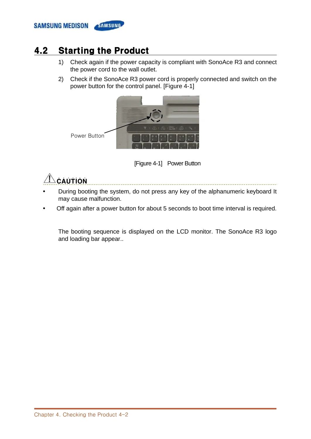
- Chapter 4. Checking the Product: Power-up verification, monitor display geometry, detailed control panel operation, soft menu navigation, and basic to detailed performance testing across B-Mode, Dual, M-Mode, Color Doppler, and Spectral Doppler
- Chapter 5. Product Structure: Architectural block diagrams, functional analysis of Front End and Back End subsystems, PSA board operations, Beamformer circuit paths, DSP/DSC processing, PC module specifications, Rear I/O panel, and power supply voltage rails
- Chapter 6. Basic Maintenance: System information auditing, Admin Mode (Service Mode) password access and diagnostic functions, software and hardware upgrade sequences, user database backup/restore, software option unlocking, and Vkey control panel diagnostics
- Chapter 7. Troubleshooting: Diagnostic workflows for power failure and abnormal shutdowns, blank or distorted monitor displays, system boot hangs, and echo image noise or missing Doppler signals
- Chapter 8. Disassembly and Reassembly: Step-by-step teardown instructions for body front, middle, and rear covers, main internal chassis, 15-inch LCD panel and hinge assembly, power supply, hard drive, cooling fans, and control panel keyboard
- Chapter 9. Probe: Transducer compatibility matrix (C2-4/20, CN4-9, CN2-8, LN5-12/40, L5-12/60, LV5-12/60, LV2-5/180, EC4-9), thermal indices, approved contact gels, protective sheath guidelines, and chemical disinfectant compatibility lists
- Chapter 10. User Maintenance: Environmental preventative maintenance, console cleaning and disinfection protocols, 10A/250V fuse replacement procedures, measurement accuracy calibration intervals, and database preservation
- Chapter 11. Service Part List: Complete illustrated parts catalog with original manufacturer part numbers for chassis plastics, internal circuit boards, LCD components, hard drive brackets, power supply assemblies, trackball units, and replacement probes
IMAGES PREVIEW
Together, these eleven comprehensive chapters equip biomedical engineers and service personnel with the authoritative factory documentation required to maintain the Samsung Medison SonoAce R3 at peak diagnostic accuracy throughout its operational lifespan.
Professional Diagnostic & Repair Capability
Utilizing the authentic Samsung Medison SonoAce R3 Ultrasound System Service Manual empowers healthcare facilities and biomedical service providers to handle complete equipment overhauls, routine electrical safety testing, sub-assembly replacements, and precise software calibrations in-house. Relying on exact manufacturer voltage tables, part numbers, and diagnostic trees eliminates diagnostic uncertainty, protects sensitive multi-element ultrasound transducers from overdrive damage, and ensures complete compliance with medical electrical safety standards. This service manual is provided as an instant PDF download immediately upon checkout, allowing technicians to start troubleshooting on any computer, tablet, or mobile device without delay, with full print capability for clinical workshop reference.




Reviews
There are no reviews yet.