
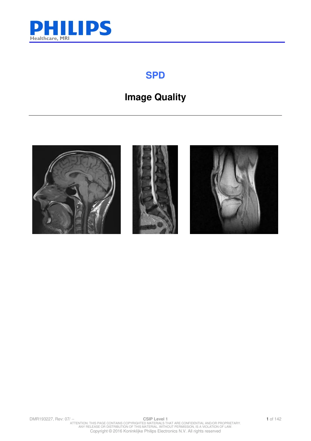
Philips MRI Image Quality Troubleshooting Spike RF Noise Artifact Diagnostic Manual DMR 193227 PDF Download
Original price was: $39.95.$24.95Current price is: $24.95.
142-page Philips Healthcare MRI Image Quality SPD, DMR 193227 Rev. 07, with detailed faultfinding procedures for spikes, RF interference, ghost artifacts, coil noise, gradient/RF-chain faults and image-quality testing across Philips MRI platforms including Multiva, Achieva, Ingenia, Intera, Prodiva and Panorama HFO. Instant PDF download.
Description
Philips MRI Image Quality Diagnostic & Faultfinding Manual – 142 Pages
This 142-page Philips Healthcare MRI Image Quality SPD, document DMR 193227, Revision 07, is a specialist diagnostic and troubleshooting reference focused on identifying and isolating MRI image-quality problems. Its stated purpose is to provide information and procedures for faultfinding image-quality issues on Philips MRI systems.
The manual is especially detailed in areas that can be difficult to diagnose from the final image alone: spikes, intermittent artifacts, RF interference, spurious noise, ghost artifacts, receive-coil noise, vibrating components, gradient-related disturbances and RF-chain faults. It combines troubleshooting workflows, service-test procedures, example fault sources, system-specific notes, analysis methods and illustrated examples.
This is not a general MRI operating manual. It is a focused image-quality diagnostic reference intended to help a service engineer move from an observed artifact or abnormal test result toward the physical, electrical, RF or environmental source of the problem.
Document Identification
- Document: SPD – Image Quality
- Product area: Healthcare, MRI
- Document number: DMR 193227
- Revision: 07
- Revision date: 2016 JUL 19
- Language: English
- PDF page count: 142
- Primary purpose: Faultfinding of MRI Image Quality issues
Philips MRI Platforms Referenced
The manual covers image-quality testing and faultfinding across a broad range of Philips MRI configurations. Its SPT specification tables and system-specific sections identify or reference platforms including:
- Achieva 1.5T
- Achieva 3.0T
- Achieva dStream / Ingenia CX 1.5T
- Achieva dStream / Ingenia CX 3.0T
- Achieva dStream XR
- Ingenia 1.5T
- Ingenia 3.0T
- Intera 1.5T
- Intera 3.0T
- Multiva
- Prodiva 1.5T
- Panorama HFO 1.0T
- Omniva – Phoenix as a gradient/system configuration entry
- Other cylindrical 0.5T, 1.0T, 1.5T and 3.0T configurations represented in the SPT system-type tables
Important scope note: not every procedure applies identically to every listed system. The document contains system-specific instructions and restrictions, and individual tests identify the applicable hardware, software release or platform. This listing therefore does not imply that every chapter applies to every Philips MRI model.
Specific Multiva Coverage
For buyers working with a Philips Multiva, this manual contains explicit Multiva-specific material rather than only generic MRI troubleshooting.
Examples include:
- Multiva included in the cylindrical 1.5T system specification-file configuration
- Multiva Galaxy identified in the gradient-configuration table
- Multiva-specific coil configuration information
- Multiva references in gradient-strip and gradient-chain troubleshooting
- A dedicated Section 13.3 – Multiva systems for spike-search-coil faultfinding
- Instructions addressing Multiva R5 behavior with C1 coils
- Alternative use of a spike search coil or suitable receive coil for localization work
This makes the manual a useful companion to a Multiva installation/service manual when the problem is specifically poor image quality, unexplained spikes, RF noise or artifact localization.
Main Subjects Covered
- SPT configuration and specification files
- Image Quality Test scans
- BODY and HEAD IQ testing
- PIQT scans
- Coil IQT and CET scans
- Analyzing IQT results
- Saving IQT reports
- Exporting DICOM images
- PIQT coil versus system head coil
- Spike artifacts
- Known spike sources
- Spike faultfinding workflows
- Raw-data inspection
- Spike determination
- Spike localization
- QPI values
- Frequency and timing analysis
- Gradient enable/disable testing
- MR System Inspector log-file analysis
- Ghost artifact measurement
- Spurious noise and RF interference
- Coil noise testing
- RF interference source localization
- C1 and spike-search-coil faultfinding
- Fat-saturation issues
- Phantom-related information
- Scan Performance Evaluation
- Patient-support simulation
- Geometric distortion information
SPT Configuration and Image Quality Tests
The manual begins with material on SPT configuration and the specification files used for different MRI system configurations. It explains the naming structure of these files and maps codes to MRI field strengths, platform families, gradient configurations, RF transmit configurations and coil types.
The document includes procedures for:
- Checking the installed SPT specification-file version
- Comparing specification files
- Downloading updated specification files where applicable
- Running BODY or HEAD IQT scans
- Running PIQT scans
- Running coil IQT or CET scans
- Analyzing Image Quality Test results
- Saving IQT reports
- Exporting DICOM images
The system-configuration tables are technically useful because they connect image-quality tests to the actual MRI configuration. For example, the document identifies Multiva Galaxy in the gradient-chain configuration information.
Spike Artifacts – One of the Core Diagnostic Sections
A large portion of the manual is devoted to spikes. These are not treated as one generic fault; the manual breaks the problem down by physical source, system component, frequency behavior, localization result and test condition.
Known sources are organized into categories including:
- Loose or vibrating mechanical parts
- Loose or vibrating cables
- RF-chain components
- Gradient-chain components
- Lighting equipment
- Shim rails
- Quench pipe components
- False-ceiling components
- System Filter Box issues
- Magnet-related parts
- Switches and other specific system hardware
- Equipment outside the MRI system
- Panorama-specific causes
- Ingenia-specific causes
Illustrated RF-Chain Spike Sources
The RF-chain section contains numerous real examples of hardware conditions that may create spikes. These include:
- Loose or broken pin diodes and capacitors in matching boards
- Loose components in detune and matching boards
- Loose or damaged components inside the Hybrid Box
- Loose screws or connectors around PICU hardware
- Loose D-connectors at PFEI/TFEI units
- Loose BNC or SMB connections
- Defective RF cables between the Hybrid Box and QBC
- Vibrating pickup coils
- Vibrating RF screens
- Vibrating coaxial cables
- Mechanical friction involving RF cables and assemblies
- Improper Hybrid Box or RF-screen contact
- RF connectors touching at the TRSW board
Where known, the manual places preventive or corrective suggestions beside these examples, making the section useful not only for recognition of a possible cause but also for narrowing the corrective action.
Gradient-Chain Spike Troubleshooting
The gradient-chain material is similarly practical. It lists potential causes such as:
- Loose bolts, nuts, washers or gradient-strip brackets
- Loose gradient brackets and clamping blocks
- Loose gradient-cable connections
- Damaged or broken gradient strips
- Defective or loose clixons
- Loose conductive strips associated with clixons
- Loose RF screens
- Vibrating cables adjacent to the gradient coil
- Moving gradient cables
- Vibrating cooling hoses
- Air-cooling hose or clamp vibration
- Gradient-cooling connections touching conductive structures
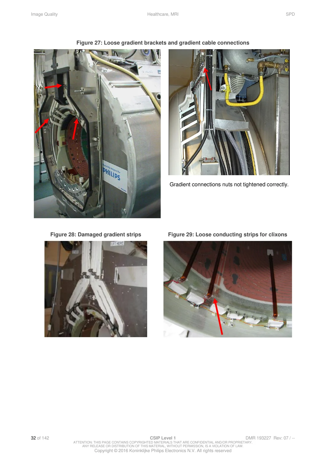
The manual contains photographs showing examples such as loose gradient brackets and cable connections, damaged gradient strips and loose conducting strips for clixons. These visual examples can help an engineer compare a suspected physical problem with documented fault conditions.
Structured Spike Faultfinding Workflows
Instead of relying on trial and error, the manual supplies step-by-step decision paths for spike faultfinding.
Separate starting workflows are included for:
- Spike problems discovered during installation
- Image-quality complaints from an operating system
- System releases supported by the MR System Inspector
- System releases not supported by the MR System Inspector
The workflow progresses through initial investigation, raw-data examination, spike determination, localization and elimination of the suspected source.
Raw Data and MR System Inspector
The troubleshooting procedures make use of system information and raw scan data to establish when and where a problem occurs.
Coverage includes:
- Collecting log files for the MR System Inspector
- Remote log collection where applicable
- On-site log collection
- Finding information on when spikes occurred
- Creating raw data for different software-release groups
- Inspecting raw data for spike behavior
- Using frequency information to narrow the suspected source
Spike Determination Tests
The manual describes multiple test variants rather than relying on one universal scan. These include:
- Spike Test Body Coil – Sweep
- Spike Test Body Coil – Fast
- Spike Test Body Coil – Standard
- Spike Test Other Coils
- Spike Localization
The document explains that different tests cover different frequency and gradient conditions, so an absence of spikes in one test does not necessarily rule out a spike problem.
Spike Localization
The dedicated Spike Localization procedure is used after spikes have been demonstrated and the engineer needs to identify the physical area or subsystem responsible.
The manual explains how to:
- Run the Spike Localization test
- Select an appropriate parameter set
- Choose start and stop frequencies
- Adjust the frequency step
- Analyze localization results
- Narrow the frequency range
- Use different RF receive coils
- Compare front and rear magnet positions
- Compare different receive-coil locations
- Test with RF switching enabled and disabled
- Disable gradient pulses
- Test X, Y and Z gradient axes separately where required
This localization process helps distinguish between potential RF, gradient, coil, magnet-area, environmental and mechanical sources.
Using Gradient On/Off Tests to Isolate the Source
The manual provides a useful diagnostic principle for determining whether the gradient chain is involved in the artifact. Gradient pulses can be disabled during selected tests. If the spikes remain while the gradient system is not being pulsed, the root cause is less likely to be within the gradient chain.
Where the gradient system is suspected, the manual describes separate testing of the X, Y and Z gradients to narrow the problem further.
Eliminating the Root Cause
After localization, the manual describes a practical elimination phase. The engineer is instructed to observe whether manipulating the suspected component changes the measured spike behavior.
The diagnostic approach includes checking for vibration, mechanical contact, loose material, poor connections and movement-dependent faults. Corrective actions described at a general level include:
- Replacing a damaged part
- Improving or tightening a connection
- Changing the fixation of a vibrating component
- Insulating parts that are touching or rubbing
- Securing loose hardware
QPI Values, Spike Frequency and Timing
The manual includes supporting information to interpret spike behavior rather than only telling the user which test button to press.
Subjects include:
- QPI values for installation
- QPI values for preventive maintenance
- QPI values for corrective maintenance
- Relationship between humidity and spikes
- Relationship between raw data and spikes
- Frequency containing the most or largest spikes
- Spike patterns
- Timing of spike patterns
Spikes Versus RF Interference
The manual contains a separate section distinguishing spike behavior from RF interference or spurious noise. This distinction is important because different test methods and different physical sources may be involved.
Ghost Artifact Measurement
Another substantial section addresses ghost artifact levels. It provides measurement setups, protocols and evaluation methods for detecting phase-related ghost artifacts.
Coverage includes:
- Ghost-artifact measurement principles
- Measurement setup for cylindrical systems
- Separate measurement setup for Panorama HFO
- Body-coil measurements
- System-head-coil measurements
- Phantom/bottle positioning
- Scan orientation
- Performing the artifact measurements
- Evaluating measured artifact levels
- System-specific typical or specification values where provided
Spurious Noise and RF Interference
Sections 11 and 12 provide a separate diagnostic path for spurious RF noise. Known sources include:
- RF cage faults or ineffective shielding
- Third-party equipment inside the examination room
- Peripheral equipment
- Lighting equipment
- RF-chain components
- Power-supply units
This helps differentiate an internal MRI-system fault from an environmental source radiating into the receive chain.
180 Hz and 35 Hz Spurious Noise Test Batches
The manual gives specific test-batch procedures for checking whether system spurious-noise levels are acceptable.
Two test types are described:
- 180 Hz spurious noise test batch
- 35 Hz spurious noise test batch
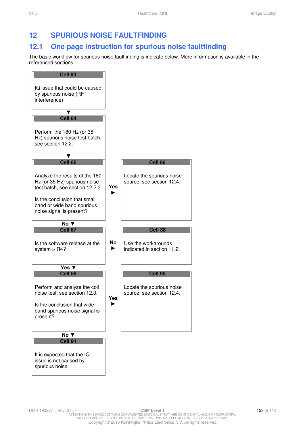
Separate batch files are identified for 1.5T and 3.0T systems. The manual then provides a decision workflow for analyzing the resulting images and determining whether small-band or wide-band spurious noise is present.
Coil Noise Test
The manual explains that some RF noise sources may not appear clearly in the standard spurious-noise batch. It therefore adds a Coil Noise Test using the body coil as receive coil.
The results are evaluated through specified receive-noise parameters. An out-of-specification result is treated as a strong indication of wide-band spurious noise and leads into the advanced localization workflow.
Locating a Spurious Noise Source
The manual provides both basic and advanced workflows for identifying the source of RF interference.
The basic workflow systematically turns potential external sources off and on while repeating the spurious-noise test. This helps identify whether a specific piece of equipment in the examination room is responsible.
The advanced approach uses RF-chain diagnostic tools and receive coils to search for the strongest interference location and narrow down the source more quickly.
C1 Coil and Spike Search Coil Faultfinding
Section 13 explains how a C1 coil or dedicated spike search coil can be used as a diagnostic probe.
Separate instructions are provided for:
- Intera and Achieva systems
- Ingenia and Achieva dStream / Ingenia CX systems
- Prodiva
- Multiva systems
The document describes a dedicated 1.5T spike search coil tuned at 64 MHz for the digital RF-chain systems and explains the relevant connection arrangement.
Multiva Spike Search Method
The Multiva section explains that the C1 coil supplied with Achieva is not normally supplied with Multiva and that Multiva R5 does not recognize the C1 coil through normal Coil Administration. The manual therefore directs the engineer toward the spike search coil or an alternative suitable receive coil arrangement for localization work.
Additional Image Quality Reference Material
The final section preserves additional information from the Image Quality Web Log, including:
- Fat-saturation issues
- Phantom information
- Noise bands with CDAS 50E terminated
- Logged preparation data
- Scan Performance Evaluation
- Patient-support simulation
- Geometric distortion
What This Manual Is
- A Philips MRI image-quality troubleshooting reference
- A spike artifact diagnostic manual
- An RF-interference and spurious-noise faultfinding guide
- A ghost-artifact measurement reference
- A coil-noise diagnostic reference
- A gradient and RF-chain fault-source reference
- A guide to spike localization using receive/search coils
- A source of illustrated examples of real mechanical, cable, RF and gradient faults
- A multi-platform diagnostic guide with explicit Multiva coverage
What This Manual Does Not Cover as Its Primary Purpose
This PDF is deliberately focused on image quality and faultfinding. It should not be confused with other types of MRI documentation.
- It is not a complete Multiva installation manual.
- It is not a general MRI operator or scanning manual.
- It is not a complete magnet ramping or shimming manual.
- It is not a full electrical schematic or wiring-diagram package.
- It is not a parts catalog.
- It is not a complete service manual for every hardware assembly.
- The document itself states that its Image Quality information is not exhaustive and that additional information may exist in other service documentation.
For a technician troubleshooting poor MRI image quality, however, that narrow focus is precisely the value of this document: instead of hundreds of pages of general installation information, it concentrates on how to recognize, reproduce, localize and eliminate image-quality faults.
Why This Manual Is Useful
MRI image-quality problems can originate from very different parts of the system: RF hardware, gradient hardware, a receive coil, a loose mechanical component, cabling, shielding, lighting, external equipment or a combination of system configuration and environment. This manual provides structured procedures for separating these possibilities.
The combination of documented fault examples, photographs, test batches, raw-data analysis, MR System Inspector information, receive-coil localization, gradient isolation and step-by-step decision workflows makes this a particularly useful diagnostic companion for Philips MRI service work.
For Philips Multiva 1.5T work, the document is especially relevant as a supplement to the Multiva SMI because it adds dedicated image-quality troubleshooting that the installation manual does not attempt to cover in comparable depth.
Important Technical Use Notice
Many procedures in this manual are intended for trained service personnel and use service applications, diagnostic modes and test procedures. System-specific restrictions and warnings in the manual should be followed, particularly where gradient strengths, RF hardware or diagnostic authorization levels are involved.
Instant PDF Download
This product is supplied as a 142-page digital PDF. After payment is completed, the manual is available for immediate download and can be retained as a technical faultfinding reference on a compatible computer, tablet or mobile device.
No printed book is shipped. You receive the downloadable PDF document described on this page.
Reviews
There are no reviews yet.