
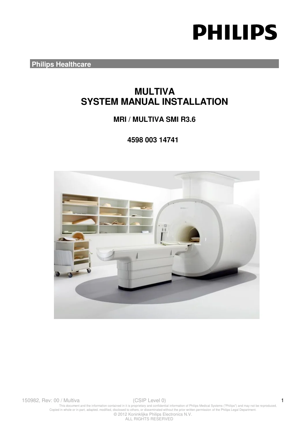
Philips Multiva 1.5T MRI System Installation Service Adjustment Drawings Manual R3.6 PDF Download
Original price was: $64.95.$39.95Current price is: $39.95.
Comprehensive 479-page Philips Multiva MRI / MULTIVA SMI R3.6 system manual covering the Multiva 1.5 T configuration, complete installation, setting to work, RF and data-acquisition adjustments, magnet ramping and shimming, gradient calibration, system-level tuning, acceptance checks and detailed 1.5T signal/cable drawings. Instant PDF download.
Description
Philips Multiva 1.5T MRI System Manual Installation – 479 Pages of Installation, Adjustment, Calibration and Technical Drawings
This is the complete Philips MULTIVA System Manual Installation, MRI / MULTIVA SMI R3.6, document number 4598 003 14741. The PDF contains 479 pages of detailed technical information for installation engineers working with the Philips Multiva MRI platform, including the documented Multiva 1.5 T configuration.
This manual goes well beyond physical installation. It follows the system from unpacking and mechanical positioning through cabinet installation, refrigeration, mains and earth connections, cooling, signal cabling, initial power-up, software and service setup, data-acquisition testing, RF calibration, magnet ramping and shimming, gradient-system adjustment, system-level tuning, safety checks, acceptance measurements and detailed technical drawings.
The manual itself states that it was written for engineers involved in the installation of a Multiva system and that it describes the complete installation, setting-to-work actions and performance measurements. This makes it a particularly useful technical reference when commissioning, re-establishing or studying the architecture and adjustment sequence of a Multiva installation.
System and Configuration Covered
The document is specifically identified throughout as a Multiva system manual. The configuration table in Section 1 identifies:
- System: Multiva
- Field strength: 1.5 T
- System configuration number: 781076
- Magnet: F2000 magnet
- Gradient configuration: Galaxy
- Gradient amplifier: Copley 781
- Gradient coil: TNF3
- Gradient cables: 12 gradient cables
The manual also contains numerous drawings and procedures explicitly labelled MULTIVA 1.5T, including magnet, RF-chain, gradient-chain, main cable-plan and cable-routing information.
Complete Manual Structure
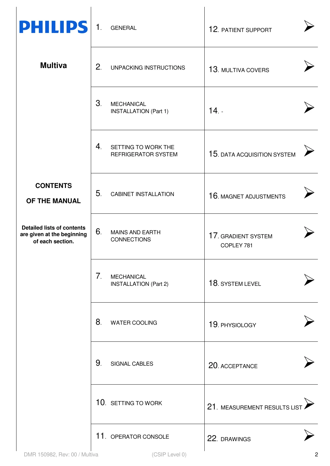
The 479-page manual is divided into a large series of technical sections. The main sections shown in the document are:
- Section 1 – General
- Section 2 – Unpacking Instructions
- Section 3 – Mechanical Installation, Part 1
- Section 4 – Setting to Work the Refrigerator System
- Section 5 – Cabinet Installation
- Section 6 – Mains and Earth Connections
- Section 7 – Mechanical Installation, Part 2
- Section 8 – Water Cooling
- Section 9 – Signal Cables
- Section 10 – Setting to Work
- Section 11 – Operator Console
- Section 12 – Patient Support
- Section 13 – Multiva Covers
- Section 15 – Data Acquisition System
- Section 16 – Magnet Adjustments
- Section 17 – Gradient System, Copley 781
- Section 18 – System Level
- Section 19 – Physiology
- Section 20 – Acceptance
- Section 21 – Measurement Results List
- Section 22 – Drawings
Installation Planning and Engineering Sequence
The manual provides a defined installation workflow rather than leaving the engineer to determine the sequence independently. It includes installation planning, prerequisites and a day-by-day installation sequence covering transport, mechanical installation, setting to work, magnet adjustment, gradient setup, system-level adjustment, performance checks and handover.
The documented workflow includes activities such as:
- Unpacking and transport into the hospital
- Positioning and alignment of the magnet
- Mechanical system assembly
- Cabinet positioning and installation
- Refrigerator-system installation and startup
- Mains and earth connections
- Water-cooling installation
- Signal-cable installation and routing
- Operator-console installation
- Patient-support installation
- Data-acquisition-system startup
- Magnet ramping and shimming
- Gradient-system setting to work
- System-level fine adjustments
- Acceptance measurements
- Safety verification and final handover
The manual distinguishes between factory pre-assembled and site-assembled magnet-system activities and gives separate installation-hour totals for these installation arrangements.
Mechanical Installation
The mechanical-installation sections cover the physical installation sequence for the Multiva system and its major hardware. These sections are intended to be used together with the drawings and cable-routing information later in the manual.
Subjects include system positioning and assembly, magnet-related installation work, cabinets, system filter box components, patient-support installation, covers, operator-console installation and the mechanical relationships between the major system assemblies.
Refrigerator, Cryogenic and Helium Work
A major portion of the manual addresses the superconducting-magnet support systems and the work required to bring the refrigerator and magnet into service.
Coverage includes:
- Setting to work the refrigerator system
- Cold-head-related installation and testing
- Cryogenic-system connections
- Liquid-helium handling requirements
- Helium filling equipment
- Helium transfer lines
- Pressure-regulator requirements
- Leak-checking equipment
- Transfer-line dimensional information
- Magnet helium-level checks
- Cold-head shutdown testing
The manual contains dimensional drawings for helium-transfer equipment and identifies tools and fittings required for filling operations.
Mains, Grounding, Cooling and Infrastructure Connections
The system installation sections include the electrical and infrastructure connections necessary before the system can be powered and tuned. The manual covers:
- Mains distribution connections
- Earth and grounding connections
- System Filter Box connections
- Liquid-cooling connections
- Water hoses and routing
- Air-pressure sensing
- Gradient-coil temperature-switch connections
- Console and system-cabinet interconnections
Signal Cables and 1.5T Cable Routing
Section 9 provides detailed signal-cable installation and routing information. The manual instructs the installer to connect cables according to the drawings supplied in Section 22 and specifically identifies drawings for:
- Magnet – 1.5 T
- Patient support
- Gradient chain – Copley 781
- RF chain – 1.5 T
- Console
- Main cable plan – 1.5 T
- Cable routing around the magnet and related assemblies
Detailed cable subjects include RF transmit cables, Hybrid Box and body-coil cabling, tune cables, receive cables, pickup-coil cables, RF signal cables, control cables, RF-load cable, magnet instrumentation cables, PFEI cabling, splitter-box connections, optical fibers and console connections.
Setting the Multiva System to Work
The setting-to-work material guides the engineer through the transition from installed hardware to an operating system ready for tuning and acceptance. It includes system prerequisites, power-on steps, configuration and initial checks across multiple subsystems.
The documented installation philosophy requires completion of earlier mechanical, electrical, cooling and cabling work before the later tuning and adjustment stages are performed.
Software, Host Computer and Service Application
The manual includes technical setup for the host computer and system software configuration required as part of installation. Covered items include:
- Checking pre-installed software
- Release, version and level verification
- Host-computer startup
- System reference and software-key configuration
- Scanner hardware configuration
- RF-coil configuration
- Hospital LAN configuration
- Software options
- Security-fix and service-pack level checking
- Nightly self-test behavior
- Hardware-error handling at startup
- Starting the Service Application
- Accessing System Test and Tuning procedures
- Starting service/test applications
The document explains that a separate Software Installation Manual is used when performing a repair software installation or a software upgrade. This SMI therefore includes the software work required for system installation and configuration but is not represented as a complete software-repair or software-upgrade manual.
Data Acquisition System – CDAS, PFEI, Reconstructor and RF Hardware
Section 15 – Data Acquisition System is one of the most technically detailed portions of the manual. It describes how to switch on, test and adjust the data-acquisition-chain hardware.
Systems and components addressed include:
- CDAS
- PFEI
- Reconstructor
- RF amplifier
- RF coils
- MEU
- Circulator
- Patient support interfaces
- Audio chain
- Quad Body Coil for 1.5 T
Quick Checks and RF System Verification
The Data Acquisition section includes system tests for:
- CDAS and PFEI
- Reconstructor
- MEU
- RF amplifier
- Circulator
- Patient support
- Audio chain
- Quad Body Coil 1.5 T
- Other RF coils
RF Calibration and Adjustment Procedures
The manual contains actual RF adjustment and calibration procedures rather than simply describing RF-system components. These include:
- Transmit attenuator calibration – calibration of transmit attenuators on the CDAS-TXR board
- Tune transmit attenuator calibration – calibration of tune transmit attenuators on the CDAS-CLK board
- Receive attenuator calibration – calibration of receive attenuators on the PFEI-MRX board or boards
- ADC calibration – calibration of ADC integral non-linearity on available CDAS-RX receive channels
- PMU test – checking Power Monitoring Unit operation in the RF amplifier
- Maximum-kW calibration of the body coil
- Quad Head Coil 1.5 T adjustment
- Hybrid Box adjustment for the 1.5 T body coil
The manual states that the tuned receive-calibration values are stored in the tuned hardware-parameters archive when they meet specification.
1.5T Quad Head Coil Adjustment
The Quad Head Coil procedure provides checks and adjustments involving:
- Frequency
- Q-factor verification
- Orthogonality
- Frequency-offset adjustment
- 90-degree phase relationship between the two coil modes
The manual identifies an adjustment frequency of 64.050 MHz for the Quad Head Coil and describes how frequency offset and orthogonality are adjusted when required.
Magnet Adjustments – 1.5 T Systems
Section 16 is a dedicated 54-page Magnet Adjustments section for 1.5 T systems. It includes detailed procedures for setting the magnet to work, ramping and shimming.
The section includes:
- MEU and ERDU testing
- RMMU or MEU battery testing
- PFEI peripheral testing
- Portable magnet power-supply setup
- Ramp preconditions
- Tesla-meter setup and use
- Current-lead insertion
- Magnet ramp-up procedure
- Magnet ramp-down procedure
- Flexible current-lead removal
- Magnet shimming
- Shimming safety requirements
- 1.5 T shimming specifications
- Shim measurement setup
- Gradient orientation
- Shim-gantry installation
- Field-decay measurement
- 12-plane shim plotting
- Iron-distribution calculation
- Shim-rail removal and installation
- Mounting shim iron
- Final actions after shimming
- System resonance-frequency determination
- Gradient-orientation verification
- Gradient-coil cooling startup
Field Decay and Magnet Verification
The magnet section contains measurement procedures for checking magnetic-field behavior, including field-decay measurements using a shim Tesla meter and specified measurement intervals. It also provides the workflow for evaluating and correcting magnetic-field homogeneity through the shimming process.
Gradient System – Copley 781
The manual contains dedicated material for the Gradient System – Copley 781 used in the documented Multiva configuration. It covers setting the gradient chain to work and continues into system-level gradient tuning and verification.
System-Level Fine Adjustments
Section 18 combines fine system adjustments with required safety actions. Technical procedures include:
- System resonance-frequency determination
- Entering the actual F0 frequency into the hardware parameter file
- RF power-reference adjustment
- Pickup-coil triplevel adjustment for the body coil
- MRI eddy-current and oscillation compensation
- Gradient parameter determination
- Channel delay and FID shimming
- Eddy-current analysis
- Gradient fine-gain calibration
- Gradient-chain verification
- Cold-head shutdown test
- Total system backup
- Site hardware configuration records
- MRL system acceptance
These procedures show that the manual does not stop after the physical installation is complete; it continues through technical tuning and verification of the installed MRI system.
Safety Verification
The manual contains extensive system-specific safety information throughout the installation process and dedicated safety actions during final system setup.
Subjects include:
- Magnetic-field safety
- Liquid-helium and helium-gas safety
- RF-coil and cable-trap safety
- Laser-light safety
- Electrical safety
- Earth-leakage-current measurements
- Helium-level verification
- Patient alarm and nurse-call testing
- Emergency procedures
- Magnet-quench procedures and preparation
- Emergency field-shutdown considerations
Acceptance and Performance Measurements
The final installation stages include Acceptance and a Measurement Results List. The installation plan identifies system acceptance, safety tests and artifact measurements as part of the final commissioning sequence.
The acceptance-related workflow includes checking tuned system hardware, recording measurement results and completing the performance checks required before handover.
Technical Drawings and System Architecture
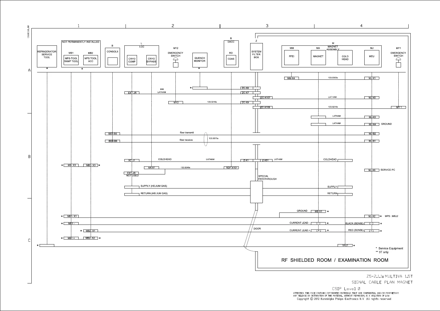
Section 22 contains detailed Multiva technical drawings. This section is particularly valuable for engineers who need to understand where major components are located and how system assemblies are interconnected.
The drawings identify or interconnect components including:
- Magnet assembly
- Magnet Electronics Unit
- Gradient coil
- Copley 781 gradient amplifier
- Gradient amplifier cabinet
- Data Acquisition System / CDAS
- DACC
- PFEI
- Reconstructor
- RF power amplifier
- Power Monitoring Unit
- Quad Body Coil
- Hybrid Box
- System Filter Box
- Liquid Cooling Cabinet
- Chiller
- Cold head
- Refrigerator system
- Patient support
- Operator console
- Host computer
- Patient monitoring and audio equipment
- Emergency switches
- Examination-room equipment
1.5T Signal and Cable Plans
The drawing package includes diagrams identified for the Multiva 1.5 T system, including:
- Signal Cable Plan – Magnet – Multiva 1.5T
- Gradient-chain drawings
- RF-chain drawings for 1.5 T
- Patient-support drawings
- Console connections
- Main Cable Plan – 1.5 T
- Detailed cable-routing drawings
These are technical system and interconnection drawings rather than merely installation photographs.
What This Manual Is
- A comprehensive Philips Multiva System Manual Installation
- A mechanical and electrical installation reference
- A commissioning and setting-to-work manual
- A data-acquisition-system test and adjustment reference
- An RF calibration and tuning reference
- A 1.5 T magnet ramping and shimming reference
- A gradient-system setup and calibration reference
- A system-level tuning and verification reference
- An acceptance and performance-measurement reference
- A source of detailed Multiva 1.5T signal, cable-routing and system drawings
What This Manual Does Not Claim to Be
To make the scope clear before purchase, this PDF is primarily the System Manual Installation for Multiva R3.6. Although it contains extensive testing, calibration, adjustment and technical drawing information, this listing does not represent it as every possible Philips Multiva service publication combined into one file.
- It is not a general operator or patient-scanning user manual.
- It is not an illustrated replacement-parts catalog.
- It is not represented as a complete component-level circuit-board schematic collection.
- It is not a complete software repair or software-upgrade manual; the document refers to a separate Software Installation Manual for repair installations and upgrades.
- Optional equipment is not necessarily included in the basic installation scope; the manual states that installation instructions for options are supplied with the applicable option.
- It should not be assumed to cover every later Multiva hardware or software revision beyond the documented MRI / MULTIVA SMI R3.6 configuration.
Why This Manual Is Particularly Useful
For a technician or engineer working with a Multiva installation, the value of this manual is the breadth of the technical workflow in one document. It does not merely show how to assemble hardware: it links the physical installation with RF and gradient cabling, software setup, data-acquisition testing, coil adjustments, magnet ramping and shimming, system resonance, eddy-current compensation, gradient calibration, safety checks and final acceptance.
The detailed Section 22 drawings add substantial practical value because they show the relationships among major MRI assemblies and provide dedicated 1.5T signal and cable plans. The 54-page magnet-adjustment section and the dedicated RF and gradient calibration procedures make the document especially useful when technical information beyond routine operation is required.
Document Identification
- Title: MULTIVA – SYSTEM MANUAL INSTALLATION
- Document designation: MRI / MULTIVA SMI R3.6
- Document number: 4598 003 14741
- Document revision: Rev: 00
- Initial version date shown: 2012-sept-19
- Brand: Philips Healthcare
- System: Multiva
- Documented configuration: Multiva 1.5 T
- Configuration number: 781076
- Gradient configuration: Galaxy
- Gradient amplifier: Copley 781
- Gradient coil: TNF3
- Language: English
- PDF page count: 479
Instant PDF Download
This product is supplied as a 479-page digital PDF. The file is available for immediate download after payment and can be retained as a technical reference on a compatible computer, tablet or mobile device.
No printed book is shipped. You receive the downloadable PDF manual described on this page.

Reviews
There are no reviews yet.