
Varian Clinac High Energy & UNIQUE Technical Reference Guide 9.5 Service Calibration Interlocks PDF Download
Original price was: $49.95.$29.95Current price is: $29.95.
261-page English Varian Clinac Technical Reference Guide for C-Series software version 9.5, covering listed High Energy Clinac platforms and UNIQUE. Includes Physics Mode configuration, Service Mode beam testing, dosimetry and position calibration, LogViewer diagnostics, interlock troubleshooting, Clinac Yield Monitor, baseline procedures and dosimetry calibration guidance. Instant PDF download.
Description
Varian Clinac Technical Reference Guide – C-Series Software Version 9.5
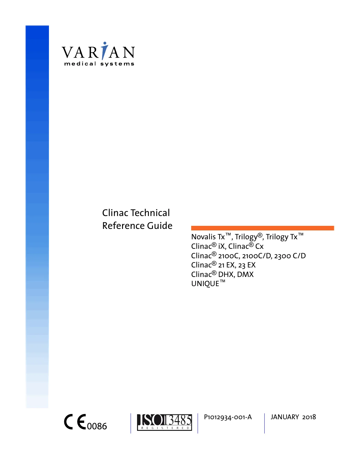
This 261-page English Varian Clinac Technical Reference Guide, document P1012934-001-A, January 2018, provides detailed reference information and procedures for configuring Varian medical linear accelerators using C-Series software version 9.5.
This edition is written for advanced accelerator users including physicists, dosimetrists and authorized service personnel. It combines Physics Mode configuration, Service Mode beam-test functions, process-data monitoring, dosimetry testing and calibration, position-readout calibration, machine-motion controls, interlock troubleshooting, LogViewer diagnostics, configuration backup/restore, hand-pendant diagnostics, Clinac System Support utilities, Yield Monitor baselining and dosimetry calibration recommendations in one technical reference.
This is substantially more technical than a routine accelerator Instructions for Use. The guide is designed to provide comprehensive access to machine operations, configuration values, diagnostic information and service-related functions on the specifically listed High Energy Clinac and UNIQUE platforms.
Models Explicitly Listed on the Cover
- Novalis Tx
- Trilogy
- Trilogy Tx
- Clinac iX
- Clinac Cx
- Clinac 2100C
- Clinac 2100C/D
- Clinac 2300 C/D
- Clinac 21 EX
- Clinac 23 EX
- Clinac DHX
- Clinac DMX
- UNIQUE
Important Applicability Note
This January 2018 edition is specifically written for Varian High Energy linear accelerators and UNIQUE. It does not list Clinac 6EX, Clinac 600C or Clinac 600CD on its cover, and this listing does not represent it as documentation for those models.
Buyers specifically seeking a guide that explicitly names Clinac 6EX should select the corresponding 6EX-covered publication rather than assuming that all Clinac Technical Reference Guide editions have identical model coverage.
Document Identification
- Document title: Clinac Technical Reference Guide
- Document ID: P1012934-001-A
- Publication date: January 2018
- Software scope: C-Series software version 9.5
- Language: English
- PDF page count: 261
- Manufacturer identified in document: Varian Medical Systems, Inc.
- Primary accelerator scope: High Energy Clinac and UNIQUE platforms listed in the guide
Complete Technical Scope
The guide is divided into a broad set of configuration, service, diagnostic and technical-reference sections:
- Accelerator specifications
- Physics Mode
- Physics Mode configuration
- Service Mode
- Service Mode beam-test menus
- Service Mode meter-value menus
- Dosimetry testing and calibration
- Position readout / PRO calibration
- Analog meter calibration
- Motor parameters and position limits
- Dynamic Beam Delivery parameters
- Service configuration backup and restore
- Communications Mode
- LogViewer diagnostics
- Morning Checkout logs
- Clinac Dynalog files
- Clinac Event Logs
- Screenshots and machine configuration backup/restore
- Hand-pendant diagnostic tests and error messages
- Detailed interlock troubleshooting
- Clinac System Support Application
- Clinac Yield Monitor
- Yield Monitor baseline establishment and troubleshooting
- Potentiometer Check utility
- Dosimetry calibration recommendations
- Transmission factors and radiation fields
- Electromagnetic compatibility data and guidance
Physics Mode – Machine Configuration
The Physics Mode chapters provide detailed access to accelerator configuration values and functions used by qualified personnel.
Configuration subjects include:
- Default Dose Rate
- Time Factor
- Passwords
- Maximum Doses
- Morning Checkout
- Customer Interlocks
- Date Format
- Time Format
- Accessories
- Field Sizes
- Accessory Target-to-Tray Distance
- Dynamic Treatments
- Enhanced Dynamic Wedge commissioning
- EDW Orientation
- Dynamic MLC communication
- Dose Export
- Extended ETR Limit
- Remote Auto Motions
- Beam Delivery Time Interlock
- Beam Gating Icon
- Record-and-Verify Interface
- Auto Mode-Up
- Skip Verify
- Beamstopper
- Low Dose Rate
- Small Motions
- Smart Connect
The guide also explains how Physics Mode configuration data is saved so that machine settings can be preserved appropriately.
Morning Checkout Configuration
The Morning Checkout section covers the configuration and management of daily checkout treatments rather than simply explaining how to start the accelerator.
Subjects include:
- Morning Checkout sequence
- RPM Respiratory Gating QA
- Adding a treatment to Morning Checkout
- Modifying an existing checkout treatment
- Removing a treatment
- Restoring a deleted treatment
- Later viewing, filtering and printing Morning Checkout logs through LogViewer
Dynamic Treatment and MLC Configuration
The guide includes configuration information for supported dynamic treatment functionality, including:
- Enhanced Dynamic Wedge commissioning
- EDW orientation
- Dynamic MLC communication
- Dose export
- Dynamic treatment modes
- Dynamic arc and wedge information
- Dynamic Beam Delivery parameters
- Clinac Dynalog analysis for dynamic treatments
Remote Motions and Machine Positioning
The Physics and Service sections provide detailed information about controlled machine motion.
Coverage includes:
- Remote Auto Motions configuration
- Large and Small Remote Motion limits
- Remote-motion error messages
- Manual gantry, collimator and couch movement
- Automatic gantry motion
- Automatic collimator motion
- Automatic couch motion
- Control of automatic motion using the hand pendant
- Cone Beam CT velocity option
- Initiating supported motion while beam is on
- Motor-axis parameters
- Motor position limits
Service Mode – Technical Access to the Accelerator
Service Mode receives extensive coverage. The manual explains the Service Mode screen, interlock status, beam data, current setup parameters, real-time parameters, machine status, menu structure, position readouts and password-controlled access.
The guide specifically treats Service Mode as a technical environment rather than a clinical treatment mode. It includes warnings that maintenance and service procedures are restricted to appropriately trained and authorized personnel.
Service Mode Beam-Test Menus
Chapter 6 provides detailed beam-test setup and control functions. The SET UP menu allows qualified personnel to construct beam-test conditions using machine parameters.
Documented beam-test subjects include:
- Set All
- Mode
- Selecting a treatment mode
- Dynamic treatment modes
- Complete or partial treatment selection
- Arc-angle entry
- Extended ranges
- Enhanced Dynamic Wedge setup
- Energy
- Rep Rate
- Dose in monitor units
- Original dose entry for partial dynamic treatments
- Exposure Time
- Accessories
- Wedge selection
- Applicator selection
- Repeat exposure
Stereotactic Test-Treatment Examples
The beam-test chapter also includes sample scenarios for setting up:
- Stereotactic fixed treatments
- Stereotactic arc treatments
These examples demonstrate how the beam-test menus are combined rather than leaving each menu function isolated from a practical setup sequence.
Beam Control, Interlocks, Triggers and Lights
The Service Mode beam-control functions include:
- Beam ON
- Beam OFF
- Viewing the interlock status area
- Interlock override functions where authorized
- General Interlock Clear
- Dose Interlock Clear
- Trigger ON/OFF functions
- Klystron Delay
- Console Gun Delay
- Lighting controls
The manual contains explicit warnings and restrictions around interlock overriding. Service Mode interlock functions must not be interpreted as permission to bypass safety conditions during clinical treatment.
Process Data and Real-Time Machine Information
The Service Mode DISPLAY menu gives access to machine process values that can be useful during diagnosis, testing and calibration.
Available displays include:
- Analog meters
- Position Readouts / PRO meters
- Digital input lines
- Digital output lines
- Accessory-slot status
- Accessory data
- Accessory error data
- Motor status
- Current control and drive status
- Common RAM through the Hex Window
- Secondary Position Readouts / SPRO
- Hardware timer output status
Motor Control and Positioning Diagnostics
The Service Mode MOTOR functions support investigation and controlled movement of accelerator axes.
The guide documents:
- Selecting manual or automatic control
- Selecting an individual motor axis
- Moving an axis manually
- Canceling motion selections
- Automatic gantry control
- Automatic collimator movement
- Automatic couch movement
- Hand-pendant control of automatic movement
- Motor status interpretation
- Motor-axis limits
- Cone Beam CT velocity-related functions
CALIB Menu – Process Value Calibration
The CALIB section is one of the most technically important parts of the guide. It covers testing and calibration functions associated with dosimetry, machine position and process values.
Subjects include:
- Calibrate Dosimetry
- Test the Dosimetry Integration System
- Test Dose Counters and Timers
- Select PRO Scale
- Analog Scaling
- Readout Calibration
- Calibrating PROs
- Canceling calibration
- Saving calibration values
- Capturing position readouts
- Calibrating an individual position readout
- Auto GoTo Test
- Analog meter gain and offset
- PRO meter gain and offset
- Motor-axis parameters
- Motor-axis limits
- Dynamic Beam Delivery parameters
- Saving Service Mode data
- Site-specific configuration
- Clinical Mode PRO scale selection
- Software/customer registration information
- Gantry clutch or clutchless drive configuration
- Velocity-check enable/disable
UNIQUE Pulse Repetition Frequency Functions
This particular 2018 guide includes a PRF Frequency option specifically identified for UNIQUE accelerators.
The guide provides functions to:
- View the current pulse repetition frequency
- Write PRF information to a file
This should not be confused with the broader low-energy C-Series PRF coverage found in certain older Clinac publications. In this edition, the PRF option is specifically identified for UNIQUE.
Service Mode Utilities
The UTILS menu provides additional diagnostic and configuration functions including:
- Reading the status of I/O ports
- Displaying I/O-port status
- Writing data to an I/O port
- Communications timeout configuration
- Executing a diagnostic self-test
- Downloading current configuration parameters
- Restoring saved configuration data
- Redirecting selected hand-pendant keys
- Printing a screen image
LogViewer – Diagnostics, Logs, Screenshots and Backup/Restore
A major difference between this 2018 edition and some earlier Clinac references is the detailed LogViewer coverage.
The guide explains that functions formerly associated with Communications Mode were moved into LogViewer. LogViewer can be used to:
- View Clinac logs
- Sort logs
- Filter logs
- Back up logs
- View screenshots
- Print supported logs and screenshots
- Back up machine configuration data
- Restore machine configuration data
The guide describes LogViewer use on the 4D Integrated Treatment Console / 4DITC workstation and, for supported functions, on an optional networked customer workstation.
Morning Checkout Logs
Morning Checkout logs are saved automatically after the daily checkout process and can be examined in LogViewer.
The guide explains how to:
- View Morning Checkout logs
- View Dynamic Treatment Summary data
- Sort logs by date and time
- Filter logs by date range
- Print individual logs
- Print Morning Checkout reports
Clinac Dynalog Files
The Dynalog section documents records produced after supported Dynamic Arc or Enhanced Dynamic Wedge treatments.
Dynalog content can include:
- Machine identification
- Machine serial number
- Treatment setup information
- Treatment type
- Energy
- Monitor units delivered
- Accessory-slot status
- Dynamic beam statistics
- Total dose delivered
- Dose standard deviation
- Dose-position standard deviation
- Number of treatment samples
- Segmented treatment-table information
- Dose and gantry-angle information for treatment segments
These records can be viewed, sorted, filtered and printed using the procedures in the guide.
Clinac Event Logs
Event Logs contain information about accelerator status when an event such as an interlock occurs. The guide explicitly notes that this data can help determine the cause of a problem.
Event-log information is organized into tabs including:
- Settings and Status
- Interlocks
- Analog Meter
- Digital I/O
- Accessory
- Various Errors
- STT Summary
The manual also explains how to view, filter and print Event Logs.
Screenshots and Machine Configuration Backup
LogViewer and Service Mode functions support additional diagnostic recordkeeping:
- Capturing Clinac console screenshots
- Viewing screenshots
- Printing screenshots
- Printing Physics Mode configuration data
- Backing up logs
- Backing up machine configuration files
- Restoring machine configuration files
The guide distinguishes which operations can be performed on the 4DITC workstation and which can be performed from a customer workstation.
Hand-Pendant Diagnostics
Appendix A contains dedicated diagnostic information for the accelerator hand pendant.
Coverage includes:
- Hand-pendant safety information
- Power-up diagnostic tests
- Runtime diagnostic tests
- Self-tests
- Error messages
- Error-message troubleshooting
Detailed Interlock Troubleshooting
Appendix B is devoted to Clinac interlocks. This is not merely a list of codes; the table associates interlock codes with their classification, the condition requiring correction and the applicable action.
The guide divides interlocks into:
- Major interlocks
- Dosimetry interlocks
- Minor interlocks
The document explains what should be recorded when an interlock occurs, including the date/time, interlock type, system state, observations and monitor units delivered.
It also explains how to handle an interlock that occurs during beam-on, including recording the remaining monitor units and correctly programming the remaining portion of a treatment where applicable.
High Energy and UNIQUE Interlock Identification
The interlock table identifies model-family-specific entries:
- Interlocks applying only to High Energy models are marked (HE).
- Interlocks applying only to UNIQUE are marked (LE) in this guide.
Examples of Interlock Areas Covered
The alphabetical interlock table includes conditions related to areas such as:
- Accessories and accessory positioning
- Facility air pressure
- Bending magnet operation
- Carousel position
- Customer-defined dosimetry interlocks
- Dosimetry check cycles
- Machine configuration
- Collimator position
- Console control
- Treatment-room door
- Dose monitoring
- Cooling-water flow
- Foil/carousel conditions
- Gas pressure
- Gun filament and bias
- High-voltage circuitry
- Ion-chamber power supplies
- Dynamic-treatment position parameters
- Motion systems
- Vacuum and other accelerator operating conditions
Clinac System Support Application
Appendix C provides substantial coverage of the Clinac System Support Application, which runs with the 4DITC environment to monitor accelerator status.
Utilities include:
- Clinac Yield Monitor
- Potentiometer Check
The application provides message/status information, Yield Monitor functions, machine-specific settings and monitoring of the primary/secondary position-readout potentiometers.
Clinac Yield Monitor
The Yield Monitor is one of the most technically valuable additions in this guide. It monitors accelerator photon yield for 6 MV beams and compares measured behavior against a baseline established for the individual machine.
The Yield Monitor uses:
- Target current
- Measured dose rate
- Predicted dose rate
- Relative deviation
- Upper and lower notification limits
- Upper and lower interlock control limits
A significant deviation between predicted and measured dose rate can indicate a beam-line problem.
Yield Monitor Fault Indicators
The troubleshooting section discusses major potential causes of abnormal Yield Monitor behavior including:
- Ion chamber drift
- Target damage
- Energy change
The guide explains characteristic patterns that can help distinguish these conditions. For example, ion-chamber drift may develop slowly and affect multiple 6 MV beam configurations similarly, while target damage can produce different yield-deviation behavior between 6 MV, 6 SRS and 6 FFF beams.
Energy changes can also cause significant photon-yield changes and may be associated with RF-power or bend-magnet conditions.
Yield Monitor Notifications and Interlocks
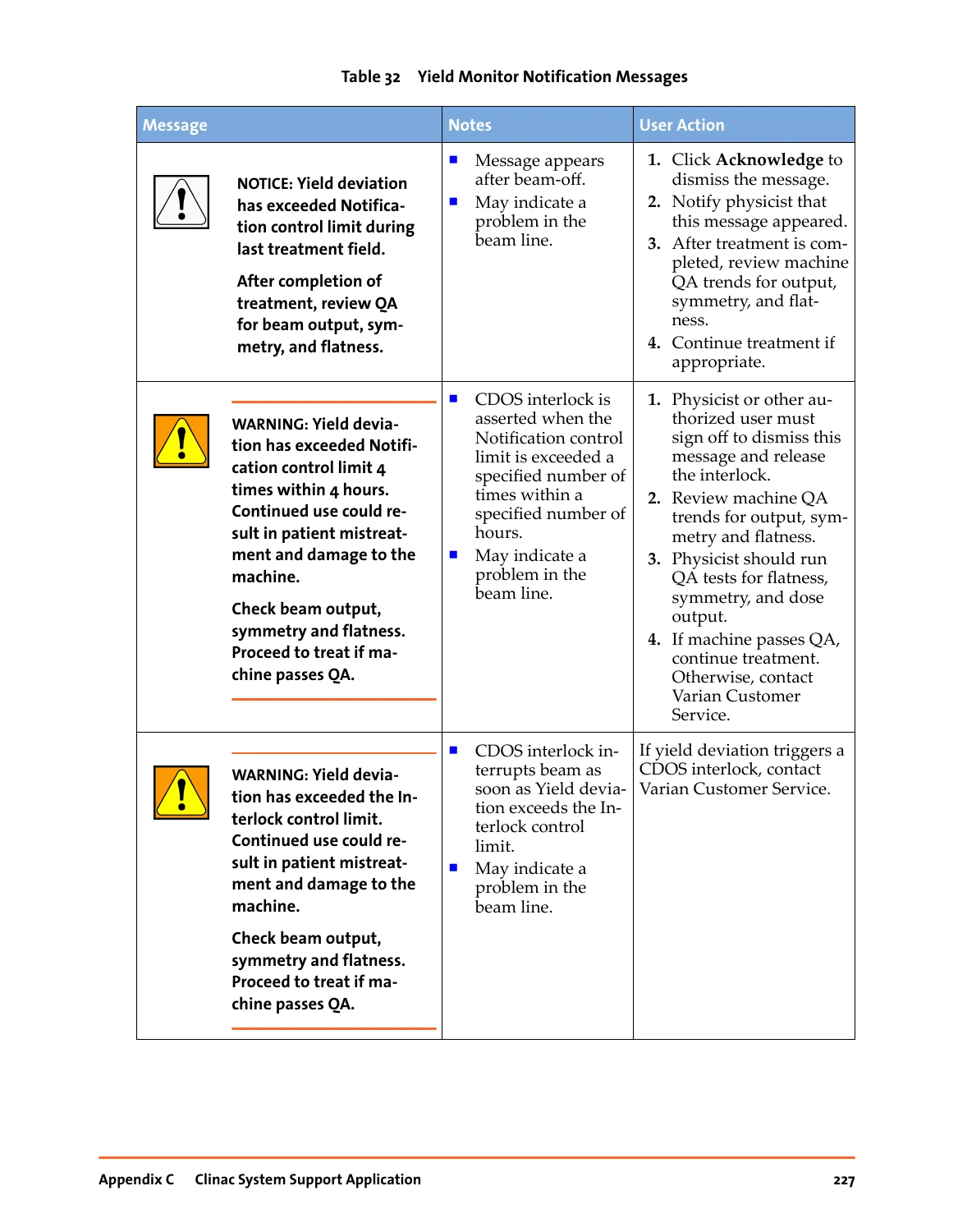
The guide describes different levels of Yield Monitor messages. Depending on the magnitude and repetition of a beam-yield deviation, the system can produce a notification or assert a CDOS interlock.
The document provides guidance for reviewing beam output, symmetry and flatness when abnormal yield messages occur, along with instructions on when service support is required.
Yield Monitor Graph and Baseline Parameters
The Yield Monitor graph displays real-time and calculated information including:
- Interlock control limits
- Notification control limits
- Relative deviation
- Dose rate
- Target current
Detailed baseline values include parameters used by the prediction model, residual-error information and higher-order correction coefficients.
Baseline Process for 6 MV, SRS and FFF Beams
The manual provides a complete procedure for establishing and verifying a Yield Monitor baseline.
The process includes:
- Gathering baseline data for each supported 6 MV beam
- Processing the collected data
- Verifying the new data
- Saving the new baseline
- Exporting data where required
The guide also discusses 6 SRS and 6 FFF high-dose beam behavior and explains that their target-current/dose-rate relationship differs from a standard fixed 6X beam.
When the Yield Monitor Baseline Should Be Reestablished
The manual provides detailed guidance rather than simply instructing the user to baseline whenever a warning occurs.
Examples of circumstances where a new baseline may or must be required include:
- After initial Clinac installation and commissioning
- After changing the dose-output calibration depth
- After major beam-line repair such as replacement of an ion chamber, target, energy switch or bend magnet
- After certain beam-tuning work that results in a Yield notification or interlock
- After specified target-current-monitor cable replacement situations
- After specified symmetry-monitor/dose-rate-integrator replacement and adjustment
When Not to Reestablish the Baseline
The manual is equally clear that repeated baselining can mask underlying accelerator problems. It specifically discusses circumstances where baselining should not automatically be performed, including routine tuning or certain dose-output recalibrations.
This section is particularly useful because it helps distinguish a genuine requirement for a new baseline from a situation in which baselining could hide deterioration of a target or another component.
Baseline Failure Troubleshooting
The guide identifies causes of baseline failure including:
- Beam switched off during collection
- Insufficient data-collection time
- Failure to collect the minimum sample quantity required by the algorithm
- Residual-error failure
The document states that the Yield Monitor requires at least 200 samples for the algorithm.
Potentiometer Check Utility
The Clinac System Support Application also contains a Potentiometer Check utility.
This utility monitors the electrical polarity of the primary and secondary readout potentiometers associated with machine axes including:
- Jaws
- Gantry
- Couch
- Collimator
The PRO-SPRO system provides position information to the gantry display and Clinac Control Console. If the utility detects a polarity mismatch, the System Support Application generates a notification.
Dosimetry Calibration Recommendations
Appendix D provides recommendations for accelerator dosimetry calibration and daily photon-output checking.
The guide discusses:
- Daily photon-output constancy checks
- Checks for all supported 6 MV beams
- 6X, 6SRS and 6FFF beam checks
- Use of recognized dosimetry protocols
- Buildup considerations for X-ray output measurements
- Calibration at dmax
- Calibration depths other than dmax
- Dose-per-monitor-unit relationships
- Non-standard calibration-depth considerations
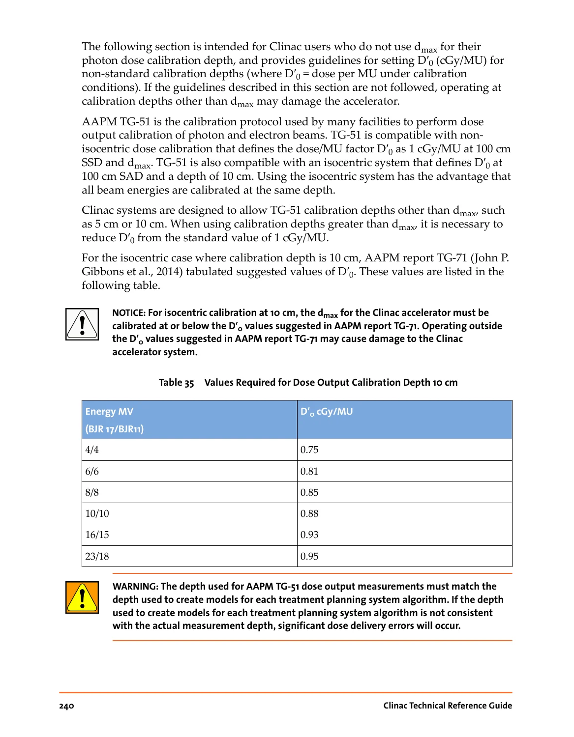
The document specifically discusses calibration at 10 cm depth and provides a table of suggested D’0 values for energies shown as 4/4, 6/6, 8/8, 10/10, 16/15 and 23/18.
Daily Photon Output Checks
The guide recommends daily output-constancy checking for photon beams and specifically identifies the need to include:
- 6X
- 6SRS
- 6FFF
It also discusses buildup and measurement methodology and references established dosimetry protocols.
Transmission Factors and Radiation Fields
Appendix E provides additional accelerator reference information including:
- Transmission factors
- Collimator transmission information
- Wedge-related transmission information
- Geometrical radiation fields
Electromagnetic Compatibility
Appendix F covers electromagnetic compatibility information and guidance, including:
- EMC emissions
- EMC immunity
- RF interference considerations
- Industrial, Scientific and Medical equipment classifications
What This Manual Is
- A 261-page English Varian Clinac Technical Reference Guide
- A reference for C-Series software version 9.5
- A technical guide for the specifically listed High Energy Clinac platforms and UNIQUE
- A Physics Mode configuration reference
- A Service Mode beam-test guide
- A process-data diagnostic reference
- A dosimetry testing and calibration reference
- A PRO / position-readout calibration guide
- A motor and machine-motion technical reference
- A LogViewer diagnostic guide
- A Morning Checkout and Dynalog reference
- A detailed interlock troubleshooting guide
- A Clinac Yield Monitor and baselining reference
- A dosimetry calibration recommendation reference
What This Manual Is Not
This distinction is important when selecting the correct accelerator documentation.
- It is not a Clinac 6EX-specific manual.
- It does not list Clinac 6EX, 600C or 600CD among the covered machines.
- It is not a complete component-level electrical schematic package.
- It is not a full wiring-diagram collection.
- It is not a circuit-board schematic manual.
- It is not an illustrated replacement-parts catalog.
- It is not a dedicated installation data package.
- It is not a complete periodic-maintenance checklist.
- It does not replace model-specific subsystem manuals or separate maintenance publications.
- Not every option shown applies to every accelerator because installed hardware, software and clinical configuration can vary.
Why This 2018 Edition Is Useful
This edition combines the established Clinac Physics and Service Mode reference material with extensive later-generation diagnostic functions such as LogViewer, Clinac System Support, Yield Monitor, beam-yield baseline management and detailed dosimetry recommendations.
For an engineer or physicist working with one of the listed High Energy Clinac platforms, it provides a single reference for machine configuration, beam-test setup, calibration, position monitoring, interlocks, logs, dynamic-treatment records and beam-yield diagnostics.
The Yield Monitor section is especially useful because it links measured dose rate and target current with potential beam-line conditions such as target deterioration, ion-chamber drift and energy change, while also explaining when a baseline should and should not be reestablished.
Important Technical and Safety Scope
The guide repeatedly restricts maintenance and advanced service procedures to appropriately trained and authorized personnel. Service Mode, interlock control, dosimetry calibration, machine movement and Yield Monitor baselining can directly affect accelerator behavior.
The manual should therefore be used as technical reference documentation by personnel whose training and authorization are appropriate to the applicable accelerator and procedure.
Instant PDF Download
This product is supplied as a 261-page English digital PDF. After payment is completed, the manual is available for immediate download and can be retained as a searchable technical reference on a compatible computer, tablet or mobile device.
No printed book is shipped. You receive the downloadable PDF document described on this page.

Reviews
There are no reviews yet.