
GE Vivid 3 Pro Vivid 3 Ultrasound Service Manual 2300164-100 Rev 7
Original price was: $39.95.$24.95Current price is: $24.95.
GE Medical Systems Vivid 3 Pro and Vivid 3 ultrasound service manual, part 2300164-100 Revision 7. Covers installation, functional checks, theory, diagnostics, replacement procedures, parts, and periodic maintenance.
Description
GE Vivid 3 Pro/Vivid 3 Service Manual for Ultrasound System Support
This GE Vivid 3 Pro Vivid 3 Ultrasound Service Manual 2300164-100 Rev 7 is the technical publication for the GE Medical Systems Vivid 3 Pro and Vivid 3 ultrasound units. It is written for service work: installation, functional verification, theory of operation, diagnostics, replacement procedures, replacement parts identification, and periodic maintenance. The manual is English-language only and is identified by part number 2300164-100, Revision 7, with the revision history showing a February 2006 software upgrade entry.
Because the Vivid 3 platform appears in both RFI and RFT hardware configurations, this service manual documents the differences that matter during troubleshooting and repair. The RFI configuration integrates Image Port, RFT, and FEC functionality onto the RFI board; the RFT configuration uses separate Image Port, RFT, and FEC boards. That distinction runs through the theory, diagnostics, service adjustments, and replacement sections, which is why the manual is useful when tracing faults through the front end, back end processor, power distribution, peripherals, and connectivity setup.
File Details
- Manual type: Service Manual
- Brand / system: GE Medical Systems Vivid 3 Pro and Vivid 3 ultrasound units
- Document number: 2300164-100
- Revision: Revision 7
- Revision date noted: February 2006
- Language: English
- Page count: 317 pages
- File format: PDF
Chapters Covered
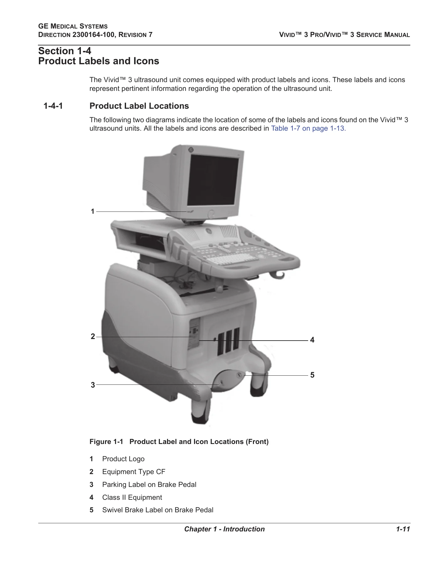
- Chapter 1 – Introduction: service manual purpose, models covered, system history, safety conventions, product labels and icons, EMC/EMI/ESD, customer assistance.
- Chapter 2 – Pre-Installation: console and environmental requirements, cooling, lighting, electrical requirements, EMI limitations, probe environmental requirements, facility needs, site requirements, networking pre-installation, connectivity worksheet.
- Chapter 3 – Installation: receiving and unpacking, wooden crate and cardboard carton procedures, component inspection, voltage and video format confirmation, EMI protection, footswitch and peripheral connections, probe and ECG connections, power connection, system configuration, connectivity setup, storing and transporting.
- Chapter 4 – Functional Checks: power on/off and boot tests, diagnostic power supply test, keyboard and footswitch checks, speaker tests, video grabbing, peripheral tests, mechanical function checks, back end processor tests, image quality tests for probes, system turnover checklist, site log.
- Chapter 5 – Components and Function (Theory): system block diagrams, front end, front board, MUX, beamformer, RFI, FEC, RFT, image port, backplane, back end processor, external peripherals, power distribution, front end cooling, common service platform.
- Chapter 6 – Service Adjustments: input AC voltage configuration, front end voltages and signal indicators, RFI/IMP/FEC/RFT/BF/MUX/FB LEDs, back end power supply voltages, VIC video signal setting, monitor operation, image quality calibration, monitor calibration, beamformer calibration, video grabbing calibration.
- Chapter 7 – Diagnostics/Troubleshooting: diagnostic menu, front end diagnostics, RFI, IMP, VME bus, RFT, FEC, beamformer, front board, MUX diagnostics, hardware report, current report, back end diagnostics, audio, ECG/phono, keyboard, media driver, computer tests, UPS test, network adapters, common service interface, error logs, utilities, PM page, automatic error log.
- Chapter 8 – Replacement Procedures: back end processor replacement, covers, plug and scan board and battery, VGA AGP, SCSI, PC2IP, frame grabber, keyboard control board, CDRW, MO drive, ECG module, PC-VIC, BEP2 power supply, hard disk, lower section components, software loading, peripheral replacement procedures.
- Chapter 9 – Replacement Parts: abbreviations, renewal parts lists and diagrams, mechanical hardware, AC system parts, front end parts, back end parts, cables, software, probes, peripherals, cabling block diagrams.
- Chapter 10 – Periodic Maintenance: periodic maintenance content for the Vivid 3 system.
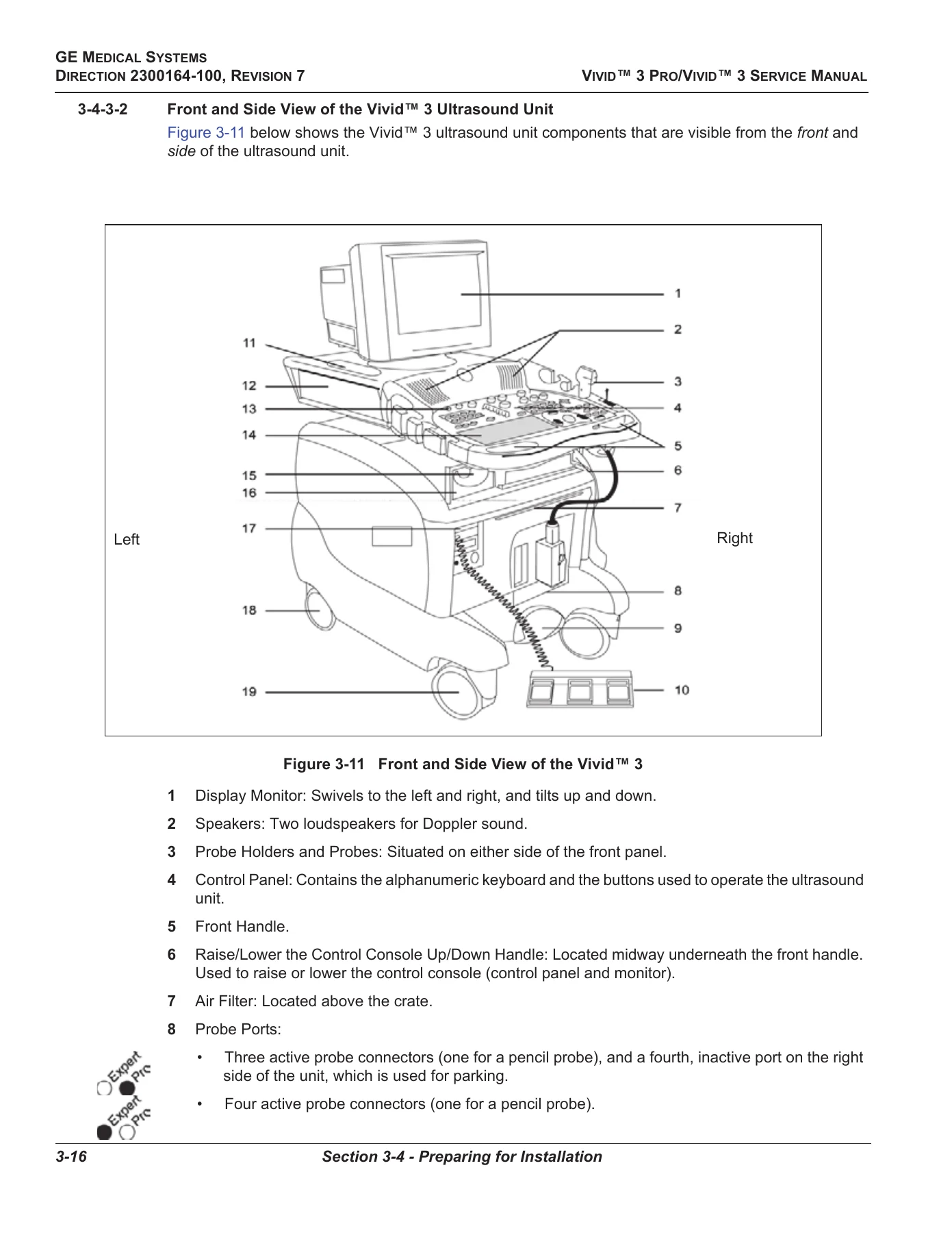
For a service technician, the value of this manual is in how it links system behavior to board-level and subsystem-level checks. Installation and functional check chapters establish baseline operation. Theory chapters explain signal flow and board functions. Service adjustment chapters identify LED states, voltage checks, monitor settings, and calibration routines. Diagnostics chapters then provide structured test paths for the front end and back end. Replacement procedures cover common field-replaceable assemblies and peripheral devices. The parts chapter provides lists and diagrams for identifying what is being replaced.
Practical Service Use
The GE Vivid 3 Pro Vivid 3 service manual is organized for staged troubleshooting rather than guessing. A technician can begin with power-on and boot checks, confirm the system configuration, verify video format and voltage settings, then move into front end or back end diagnostics depending on the symptom. The diagnostic section includes auto sequence testing, manual board tests, LED interpretation, voltage monitoring, temperature checks, error logs, and hardware reports. When a fault leads to replacement, the manual identifies BEP components, lower section components, software loading steps, and peripheral replacement procedures.
Installation coverage is also detailed. The manual describes receiving and unpacking from either the wooden shipping crate or the cardboard shipping carton, component inspection, system acclimation time, voltage confirmation, video format confirmation, connecting the footswitch, probes, ECG, peripherals, and power source, then configuring hospital information, system options, printers, VCR/ECG settings, and connectivity. For sites using DICOM, EchoPAC, or a Prosolv workstation, the connectivity setup section covers local network settings, DICOM server configuration, dataflow validation, and spooler status.
What This Manual Helps You Do
Use this manual to prepare a Vivid 3 or Vivid 3 Pro site, verify correct installation, perform functional checks after service, interpret front end LED states, run front end and back end diagnostics, perform calibration after board replacement, identify replacement parts, and follow periodic maintenance. It also supports service planning by documenting physical specifications, electrical requirements, environmental limits, peripheral connections, and transport precautions. The ultrasound system is a medical device with high-voltage and mechanical hazards, and the manual includes safety warnings for electrical, mechanical, probe-handling, and transport risks.
If you maintain GE Vivid 3 ultrasound equipment, this service manual gives you the document structure to work from: chapter-level procedures, board-level diagnostic tests, system configuration screens, replacement sequences, and parts diagrams. It is not a user operating manual; it is a service publication intended for qualified service personnel who need installation, theory, adjustment, diagnostics, replacement, and parts information in one reference.
Get the GE Vivid 3 Pro/Vivid 3 Service Manual
IMAGES PREVIEW
The GE Vivid 3 Pro Vivid 3 Ultrasound Service Manual 2300164-100 Rev 7 supports the work that matters on this ultrasound platform: correct installation, safe functional testing, systematic diagnostics, calibrated adjustments, and informed replacement decisions. Having the right part number, revision, board-level test sequence, and configuration reference reduces guesswork and helps protect the equipment, the operator, and the patient. This is an instant PDF download after payment, with no shipping and no waiting for a physical copy. You can keep it on a service laptop, tablet, or phone, print the sections you need for the bench, and return to the diagnostic and replacement procedures whenever the system requires service.




Reviews
There are no reviews yet.