
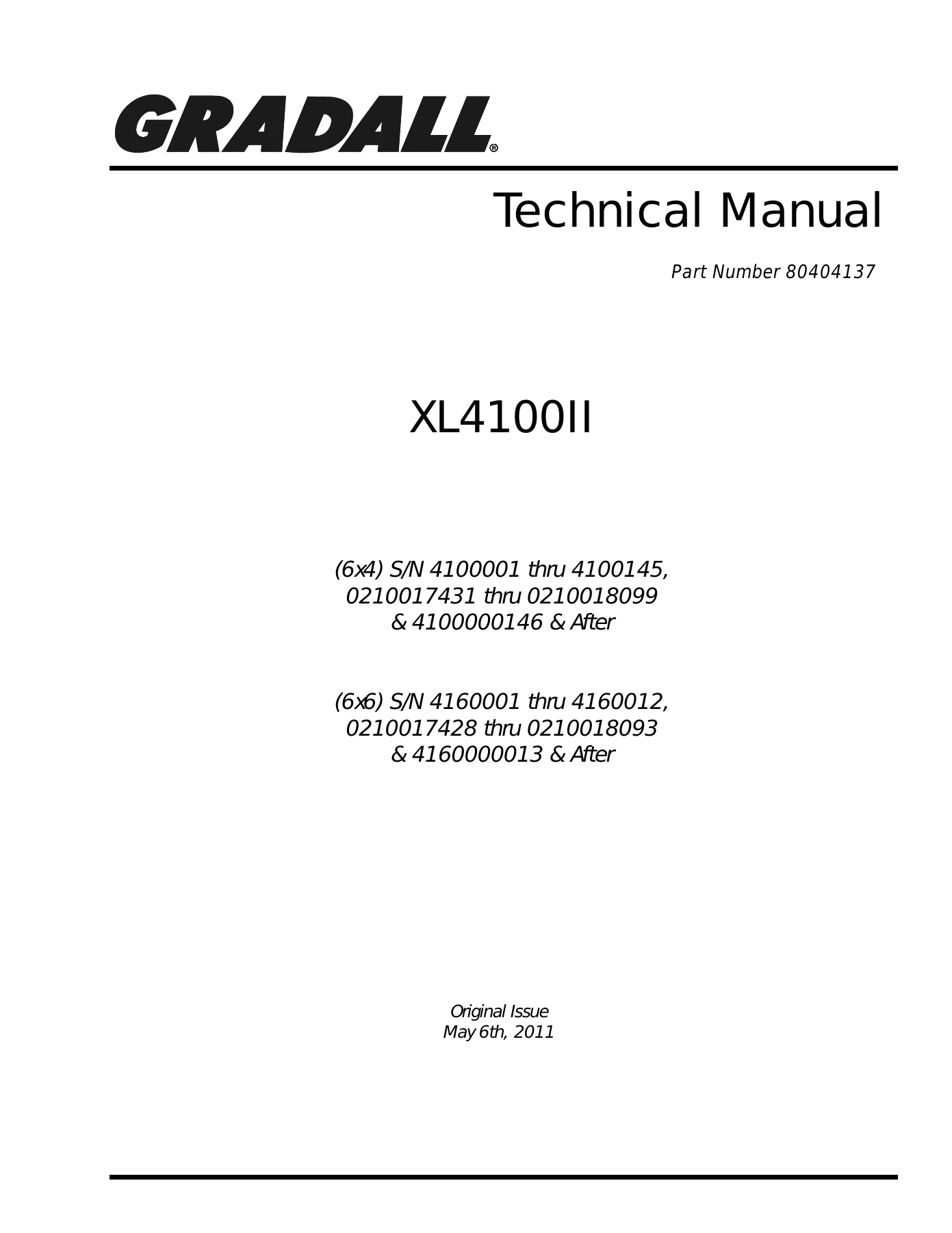
Gradall XL4100II Technical Manual 80404137 – 6×4 & 6×6 Excavator Electrical & Hydraulic Service Repair PDF
Original price was: $49.95.$29.95Current price is: $29.95.
Complete Gradall XL4100II Technical Manual (Part Number 80404137) covering 6×4 and 6×6 highway speed excavators. Full electrical system diagrams, hydraulic circuits, pressure settings, maintenance schedules, and component overhaul data in one instant-download PDF.
Description
Gradall XL4100II Technical Manual – Part Number 80404137
This is the complete Gradall XL4100II Technical Manual, published under part number 80404137 and written for the highway speed excavator line. It combines the electrical system service information, the full hydraulic system operation and repair guide, the hydraulic pressure setting manual, lubrication and maintenance schedules, and the Eaton Fuller transmission service content into one PDF. Whether you are tracing a wiring fault in the upper harness, setting pilot pressure at the manifold, resealing a hoist cylinder, or rebuilding a remote drive PTO, the diagrams and specifications are here.
File Details
- Manual type: Technical / Service & Repair Manual
- Brand: Gradall
- Model: XL4100II
- Part number: 80404137
- Language: English
- Format: PDF
- Coverage: 6×4 and 6×6 highway speed excavators
- Page count: 424
Serial Numbers Covered
The manual is written against these machine groups:
- (6×4) S/N 4100001 thru 4100145, 0210017431 thru 0210018099 & 4100000146 & After
- (6×6) S/N 4160001 thru 4160012, 0210017428 thru 0210018093 & 4160000013 & After
Chapters Covered
Electrical System Manual
The electrical section opens with a 12V system overview and color circuit diagrams intended to be used alongside the electrical schematic during troubleshooting. It covers the upper and chassis PCBs, harness routing, remote steer pedal and valve wiring, high/low range shift relays, travel relay logic, and the swing brake time delay circuit. Connector repair guidance, wire designations, digital volt/ohm meter testing notes, and welding precautions for the processors and battery leads are included. Full fuse and relay layouts for both the chassis PCB and upper PCB are provided.
Hydraulic System Operation & Overview
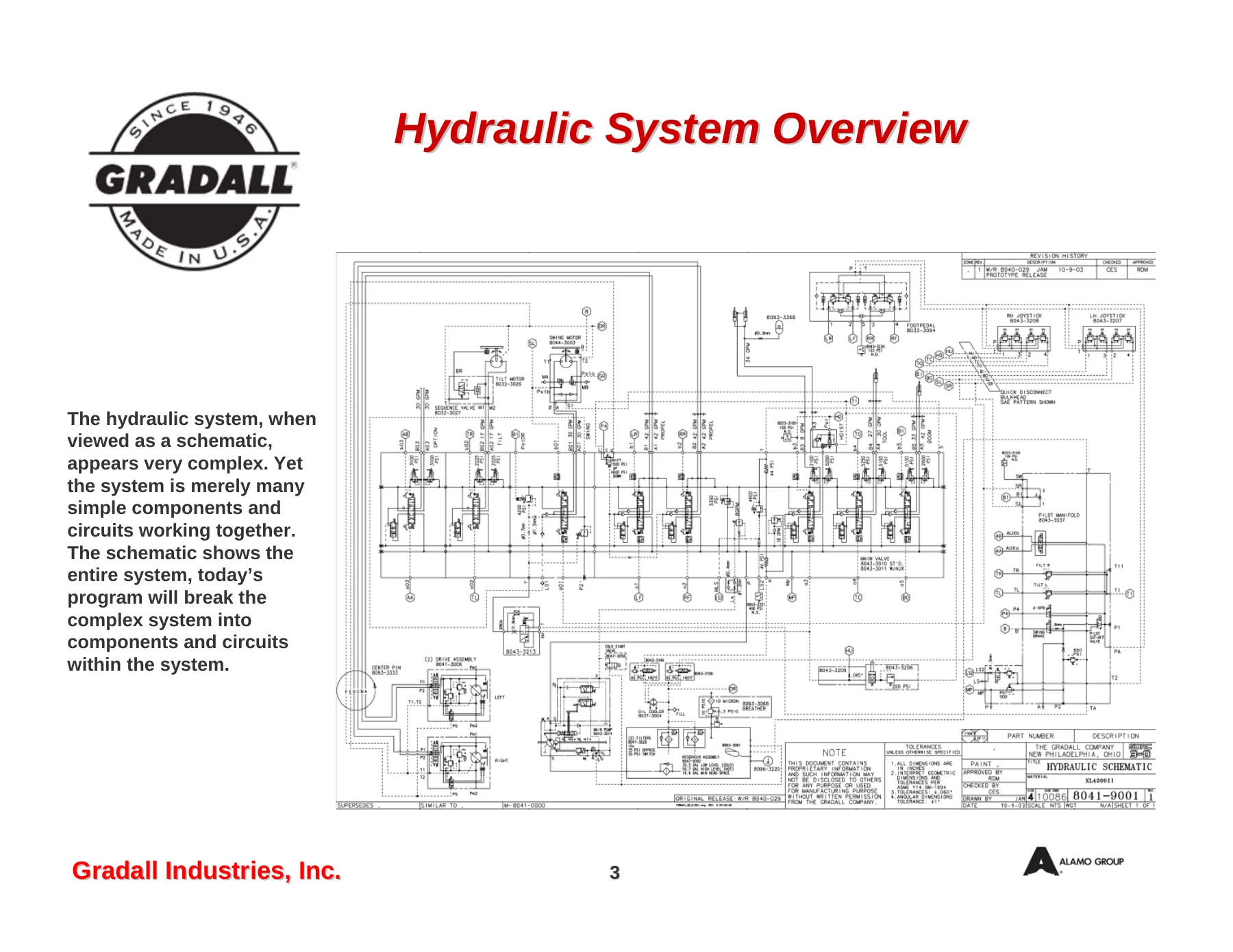
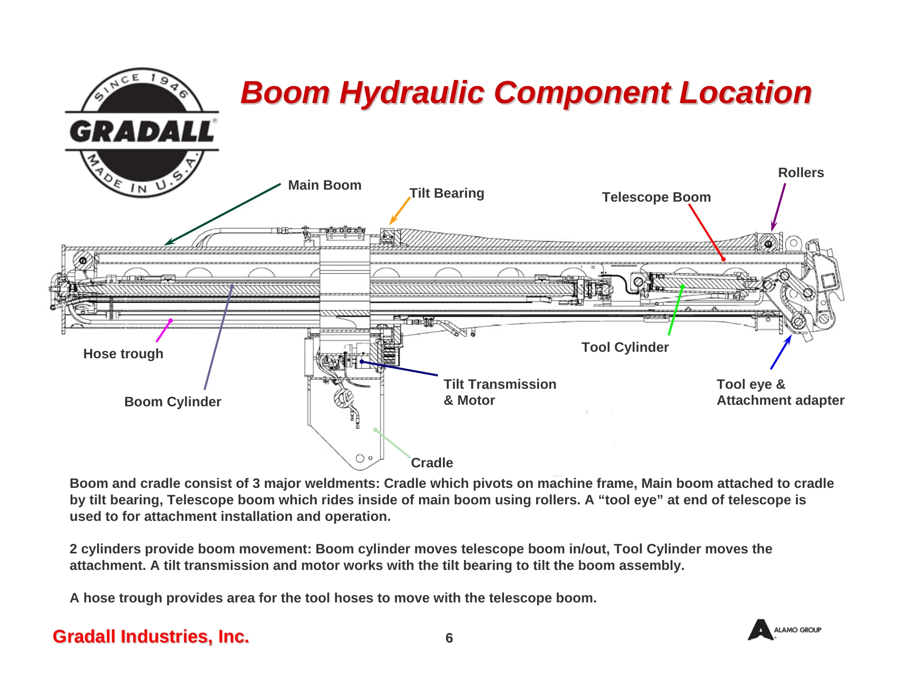
This chapter explains the variable flow, load sensing hydraulic system used across the XL series highway speed machines. It breaks the schematic into components and circuits, covering the reservoir and return filter, power unit and main pump location, remote drive motors and PTOs, centerpin, remote steering, and power steering. Frame and boom hydraulic component locations are illustrated with callouts for the main valve, pilot manifold, hoist circuit, cooling package, heater unit, A/C unit, swing motor and transmission, tilt bearing, and boom rollers.
Reservoir, Filters & Cooling
Detailed coverage of the 38 gallon hydraulic reservoir, the 10 micron in-tank return filter, suction screens, and the 10 PSI breather assembly. Includes the hydraulic fluid level switch, hydraulic oil temperature switch, filter condition switch, filter bypass operation, and the heat exchanger circuit with its 48.5 PSI and 101.5 PSI check valves. The hydraulic cooling fan motor, fan valve, flow regulator, and the 150°F temperature switch are documented, along with the cooler fan solenoid resistance value.
Center Pin & Power Unit
The center pin section covers the one-piece housing and pin design, the combined pump outlet port, and the 24 circuit electrical center pin mounted on top. The power unit assembly chapter explains how the diesel engine, transmission, and three PTOs work together for highway speed and remote operation, including the air-shifted main PTO and remote PTOs, pump drive, and remote drive motors.
Main Hydraulic Pump
The main pump is documented as two variable displacement axial piston pumps with a combined flow of 65 GPM. The front pump uses a DR control with approximately 305 PSI standby and 4500 PSI cutoff; the rear uses a DFR control with approximately 260 PSI standby and 3625 PSI cutoff. Pump output pressure, load sense pressure, washplate angle, PTO speed, and pump RPM relationships are all spelled out, along with the spring-to-full-stroke and hydraulic de-stroke behavior.
Pilot System, Joystick & Main Control Valve
The pilot system chapter covers the 550–600 PSI pilot operating pressure, the 650 PSI safety relief, pilot cutoff solenoid, swing brake solenoid, and proportional tilt solenoids. Joystick construction, spool and spring pack operation, handle switches, and control pattern change procedures are illustrated. The main control valve chapter covers the monoblock valve, bolt-on swing and heater/A/C sections, the auxiliary hydraulic option, and the inlet section functions: primary pressure relief, load sense orifice shuttle, flushing valve, load sense drain valve, tank/cooler check valves, load sense relief, and central load sense orifice. Valve operation is shown in neutral, shifted to A port, and shifted to B port, plus multiple function operation when flow demand exceeds pump output.
Boom, Tool, Hoist, Swing & Tilt Circuits
Each major work circuit is covered as its own section. The boom circuit covers boom cylinder routing, boom retract, and the boom regeneration circuit used during boom extend. The tool circuit covers the tool valve, tool cylinder, telescope tool circuit tubes, and hose trough routing. The hoist circuit covers the hoist lock valve, hoist up cushion circuit, and the hoist limit valve adjustment. The swing circuit covers the swing valve module, swing priority check valve, two-stage swing motor relief valves, swing brake release time delay logic, and the planetary swing transmission and brake assembly. The tilt circuit covers the tilt valve, tilt brake sequence valve, gerotor tilt motor, and the tilt transmission and bearing.
Heater, A/C, Remote Drive & Steering
The heater and A/C chapter documents the heater and A/C valve, 3000 PSI heater relief setting, proportional solenoid, hydraulic heater unit (motor and pump), A/C drive motor, compressor, dryer, condenser, and air handler components. Remote drive covers the counterbalance valve, propel motors, remote travel switch, brake release valve, and remote drive PTO removal and replacement with torque values and Loctite requirements. Steering covers the power steering pump, steering valve, flow divider, travel/remote solenoid, and steering cylinder circuit.
Hydraulic Pressure Setting Manual
A dedicated chapter walks through the system pressure settings with test port locations and target values. Covered settings include flushing pressure, pump differential pressure, joystick pilot pressure, propel forward and reverse, boom retract and extend, hoist down and hoist up holding valve, hoist port regulator low and high side, tool extend and retract, tilt left and right, swing regulator high and low stage, dynamic braking, system dump, A/C and heater pressures, and power steering relief. Cycle times are listed alongside the pressures.
Maintenance, Lubrication & Torque
Lubrication and maintenance charts give service intervals, recommended lubricants, and capacities for the engine crankcase, cooling system, hydraulic system, upper cab heater, steering system, swing brake, swing bull gear, swing transmission, tilt bull gear, tilt transmission, transmission, tandem axles, transfer case, and front axle. A torque chart covers extension boom roller eccentric keepers, boom cylinder rod retainer, main boom roller eccentric keepers, swing bearing, swing motor, swing transmission, tilt bearing, tilt motor, tilt transmission, and wheel lug nuts. Additional service content covers the air dryer, clutch adjustment procedure, the hydraulic heater circuit, and the R-134a A/C system operation.
Eaton Fuller Transmission Service Manual
The transmission section includes the Eaton Fuller heavy duty transmission service manual (TRSM-0430) content for the 8-speed LL, 9-speed, and 13-speed models, covering model designations, lubrication, power flow, timing, torque recommendations, tool references, preventive maintenance, disassembly and reassembly, air system range shift, splitter shift, and the tapered roller bearing shimming procedure.
What This Gradall XL4100II Manual Lets You Do
With the full XL4100II technical manual on hand, you can diagnose and repair the electrical system using the color circuit diagrams and fuse/relay layouts, then move straight to the hydraulic side and set the machine back to factory pressures using the dedicated pressure setting chapter. Every major work circuit — boom, tool, hoist, swing, tilt, remote drive, steering, and climate control — has its own section with component locations, schematics, and adjustment values. Component overhaul content covers the main pump, main control valve, swing transmission, tilt transmission, hoist and boom cylinders, and the remote drive PTOs.
Correct procedures and specifications matter on a highway speed excavator. A pilot pressure set wrong will make the machine feel sluggish or jerky. A hoist holding valve out of spec can let a loaded bucket drift. Swing regulator pressures that are not matched to the motor two-stage relief will shorten brake and transmission life. The Gradall XL4100II technical manual gives you the numbers, the test ports, and the adjustment sequence, so the job is done once and done right.
IMAGES PREVIEW
This Gradall XL4100II service repair manual is delivered as an instant-download PDF. No shipping, no waiting. Open it on a laptop or tablet in the shop, print the pages you need for the job, and keep the rest on file. The diagrams stay legible on screen and on paper, and the pressure setting chapter is laid out so you can work straight down the list during a system check.



Reviews
There are no reviews yet.