
Grove RT9000E Crane Parts Manual 2010 – Serial 230986 PDF Download
Original price was: $44.95.$26.95Current price is: $26.95.
Complete 1,154-page Grove RT9000E parts manual for crane serial number 230986, dated June 2010 (Rev 001). Covers boom, superstructure, carrier, outriggers, hydraulics, electrical, LMI iFlex 5, transmission, axles, engine and decals with exploded views and part numbers throughout.
Description
Grove RT9000E Crane Parts Manual – Serial Number 230986
This Grove RT9000E parts manual is the complete machine component index and parts catalog for crane serial number 230986, published by Manitowoc Cranes with a revision date of June 07, 2010 (Rev: 001). At 1,154 pages, this is the comprehensive parts reference covering every major assembly, sub-assembly, and component of the RT9000E rough terrain crane, and it also includes RT9130E nomenclature and decal content. Whether you are ordering a single seal or rebuilding an entire assembly, this Grove RT9000E parts manual for serial 230986 gives you the item numbers, part numbers, descriptions and quantities needed to get the right component the first time.
File Details
- Manual Type: Parts Manual / Machine Component Index
- Brand: Grove (Manitowoc Cranes)
- Model: RT9000E
- Serial Number: 230986
- Date: June 07, 2010
- Revision: 001
- Language: English
- File Format: PDF
- Page Count: 1,154 pages
Chapters Covered
The Grove RT9000E parts manual is organized as a machine component index, with every section broken down to part-number level. Key areas include:
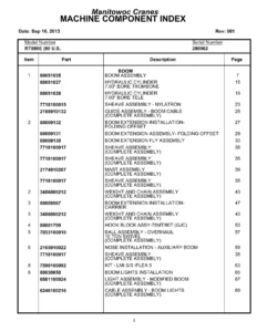
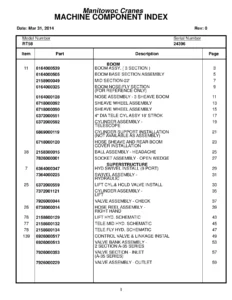
- Boom assembly, sheave installation, sheave assembly and cable guide assembly
- Cylinder assemblies – 9 1/4 inch telescope (dual rods), 7 1/2 inch telescope and 2 inch pin removal
- Upper lift pin installation, weight and chain assembly and boom removal kit
- Luffing extension 11-18, swing-away boom 11-18M and mounting parts (1.3M, 7M, 10M, 11-18M)
- Sheave holder, E-parts terminal box and jib mounting parts (7M, 11M, 11-18M)
- Jib comp parts 18M, hook block assembly – 80 ton, quick reeve and overhaul ball assembly – 10 ton swivel
- Nose installation – auxiliary boom, hookblock tie-down installation and boom lights installation
- LMI boom kit – iFlex 5 (BCS), cable reel assemblies (176 ft and 87 ft), slipring assembly (11 cond.), roller guide assembly and A2B flag assembly
- Wedge socket adapter kit, LMI boom kit installation, LMI bi-fold boom ext installation kit and LMI system installation kits
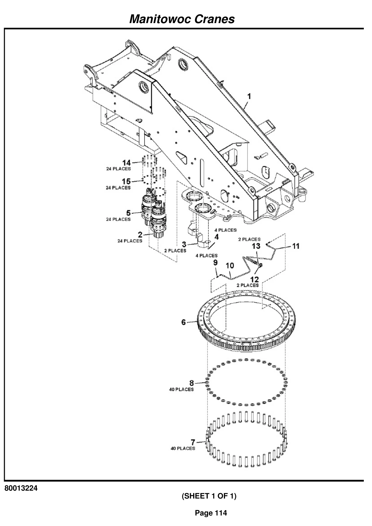
- Superstructure, turntable weld and drive installation, swing box assembly (Model PG702 PS) and hose reel installation
- Brake assembly hydraulic, motor assembly hydraulic, hose kit (hose reels) and swivel installations (electric, water and hydraulic, 11-port, 2-port water)
- Ring assembly – slip 15 conductor, lever installation – counterweight removal and valve installations
- Valve assemblies – control, counterweight, selector, pressure reducing sequence, directional control, dual pilot operated check, solenoid and double solenoid
- Accumulator assembly – hydraulic oil, valve – manual bleed off pressure and hydraulic lines installations (supply, pressure, return, telescope, cab, steer, brake, lift, main and auxiliary hoist)
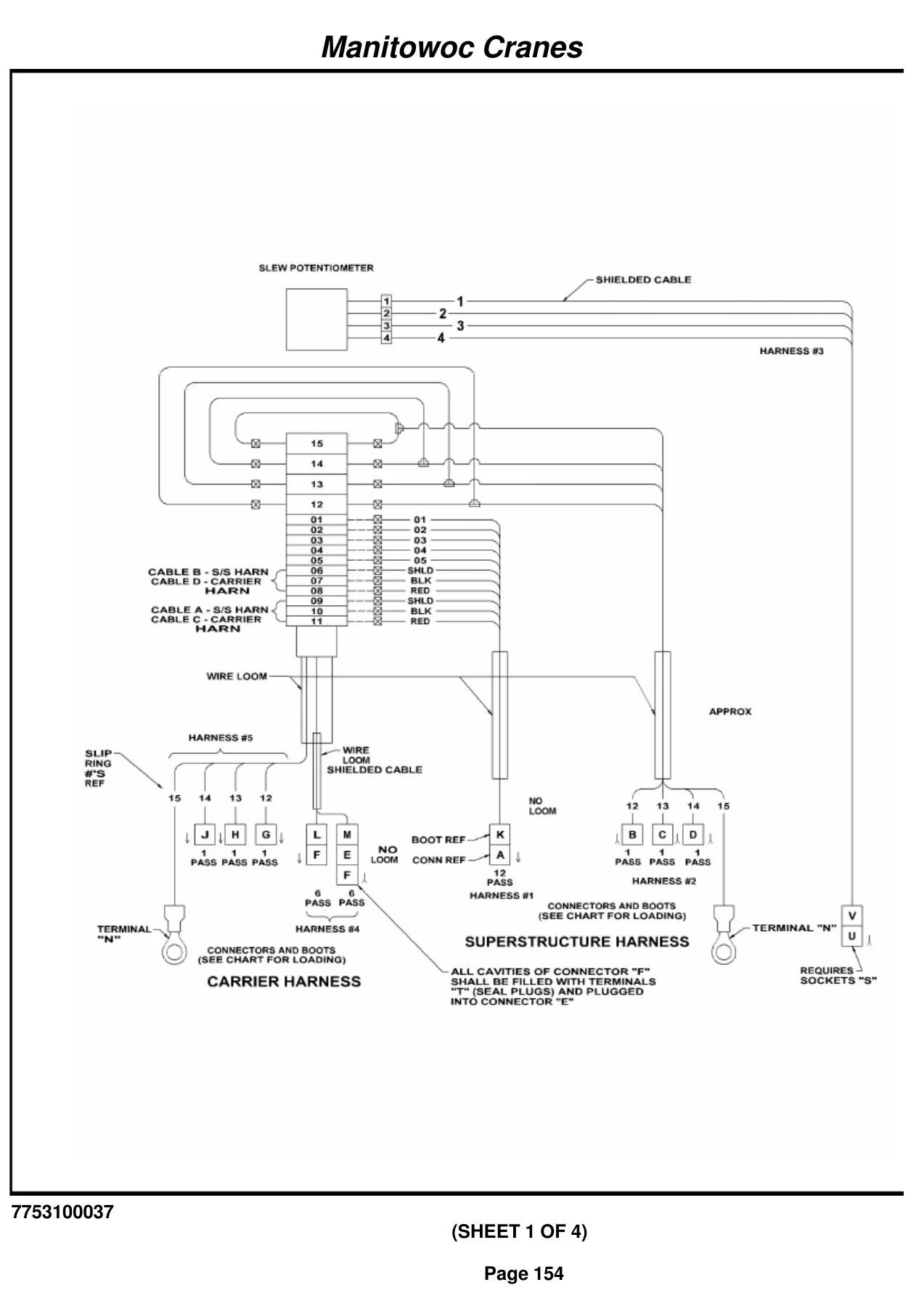
- Electrical system installation – superstructure, harness assembly – SS and switch assembly – proximity
- Turntable lock pin installation, hose retainer installation, swing lock installations and swing lock assembly
- Superstructure cab installation, cab assembly, cab weld, door installation, skylight assembly and window assembly
- Control seat installation and assembly, single axis controller, handle assembly (w/solenoid) and harness assembly – seat
- Spotlight installation, strobe light installation, front console installation and assembly and front console harness
- Air conditioning and heater installation (cab), cab heater and air conditioner kit and air conditioning lines installation
- Pedal installations – telescope, brake, throttle – and treadle valve assemblies
- Sun screen installation, binder installation, cab tilt installation and cab rear cover installation
- LMI system installation (superstructure), hydraulic air conditioner unit 12 volt and LMI internal light bar installation
- LMI iFlex 5 cab kit, central unit – iFlex 5, graphic console (ver.) – iFlex5 and S/S wire harness (BCS)
- Transmission shifter installation, steer valve installation and steering control valve
- Kitter series cab std comp kit, air conditioner switch installation and boom light switch installation
- Pole installation – jib release
- Frame and frame weldment complete
- Outrigger box assembly – front, outrigger beam assembly, outrigger jack cylinders (6 1/2 inch, 2 1/2 inch, 4 inch power pin) and outrigger control valve
- Outrigger box harness assembly, fender installation, hood installation – engine and front sub assembly – hood
- Float installation – outrigger, exterior lights and alarm installation, battery box cover installation and rear view mirror installation
- Counterweight stand installation, hydraulic/transmission oil cooler installation and storage tray mat installation
- ESI-Carrier RT9000E3, carrier harness assembly, engine relay panel assembly and relay panel harness and cable kits
- Outrigger pin controls box assembly, LH remote O/R removal cable assembly
- Lift cylinder travel support installation and assembly, bottle jack (modified) and bottle jack cylinder assembly
- Hydraulic reservoir installation and assembly, hydraulic reservoir and filter assembly
- Hydraulic valve installation without differential-carrier, integrated outrigger/rear steer valve assembly, axle disconnect and parking brake valve assembly and double solenoid valve assembly
- O/R hydraulic lines – carrier, supply/pressure/return lines and solenoid valves (12V, 2-way N.O.)
- Rear axle lockout hydraulic lines, service brake hydraulic lines – disc, axle disc and park brake lines and front steer hydraulic lines
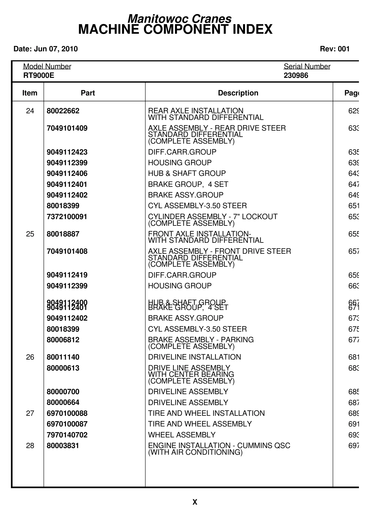
- Rear axle installation with standard differential, rear drive steer axle assembly, diff. carrier group, housing group, hub and shaft group, brake group (4 set) and brake assembly group
- Cylinder assembly – 3.50 steer, cylinder assembly – 7 inch lockout
- Front axle installation with standard differential, front drive steer axle assembly
- Driveline installation, drive line assembly with center bearing and driveline assemblies
- Tire and wheel installation and assembly, wheel assembly
- Engine installation – Cummins QSC (with air conditioning), engine assembly, torque converter assembly, torque converter group, charge pump and regulating valve group and dual pump disconnect group
- Pump assemblies – 2-section gear and gear with flow control
- Engine hydraulic lines installation, engine electrical system installation and engine cable kit
- Transmission installation, transmission assembly – 36000 series, cover groups, gear set groups, gear groups, drive groups, shaft groups, clutch groups, valve mounting group and valve assembly group
- Transmission filter/lines installation, filter assembly, radiator installation and assembly, cooler assembly (radiator/charge air), surge tank assembly, fuel tank installation and assembly and coolant strainer installation
- Pump disconnect installation, rear steer hydraulic lines installation, pintle hook installation and assembly, block heater installation and sling assembly
- Decal installations – RT9000E standard, cab, carrier, superstructure, boom – plus RT9130E nomenclature and Spanish decal content
This Grove RT9000E parts manual goes far beyond a simple component list. Each section presents the parts breakdown with item numbers, part numbers, descriptions and quantities, supported by exploded-view illustrations, assembly drawings and hydraulic and electrical schematics where applicable. For the RT9000E crane owner, fleet mechanic or parts specialist, this is the reference that makes ordering correct components possible – every fastener, seal, cylinder component, valve, hose, harness and major assembly is indexed and identified.
Why This Grove RT9000E Parts Manual Matters
Ordering the wrong part for a rough terrain crane is expensive and time-consuming. The Grove RT9000E parts manual eliminates guesswork by tying every component to its exact part number, assembly group and illustration. Whether you are rebuilding a telescope cylinder, replacing a swing box component, tracing a hydraulic line or refreshing cab and control seat hardware, the catalog structure lets you navigate from top-level assembly to individual part in a logical sequence.
IMAGES PREVIEW
The 1,154-page scope covers the complete RT9000E machine – boom, superstructure, carrier, outriggers, powertrain, axles, hydraulic system, electrical system, cab, LMI system and decals. The LMI iFlex 5 sections, in particular, provide detailed breakdowns of the cable reels, slip rings, roller guides and A2B switch assemblies that keep the rated capacity limiter functioning correctly. The transmission section breaks down the 36000 series into cover groups, gear sets, shafts, clutches and valve groups, giving a complete picture of the drivetrain internals.
For hydraulic work, the manual includes valve assemblies for control, counterweight, selector, pressure reducing sequence, directional control, dual pilot operated check, solenoid and double solenoid functions, plus the accumulator assembly and all the hydraulic line installations across superstructure, cab, carrier and engine. Electrical content spans the superstructure harness, front console harness, seat harness, engine relay panel and carrier harness, with connector and terminal details throughout.
All content is presented in English with the original Manitowoc Cranes formatting. The document also includes RT9130E nomenclature and decal installation pages, making it useful for cranes carrying the RT9130E designation as well.
Get the Grove RT9000E Parts Manual – Instant PDF Delivery
This Grove RT9000E crane parts manual is delivered as an instant PDF download after payment. No shipping, no waiting for a physical book to arrive. The file works on any device – laptop, tablet or smartphone – and individual pages or complete sections can be printed for use in the workshop or parts department. With 1,154 pages of part numbers, exploded views and assembly references for serial number 230986, this is the practical reference that keeps an RT9000E crane serviceable and correctly maintained.

Reviews
There are no reviews yet.