
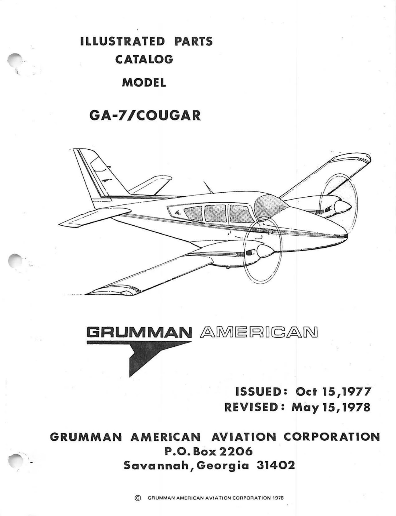
Grumman American GA-7 Cougar Illustrated Parts Catalog
Original price was: $29.95.$17.95Current price is: $17.95.
Comprehensive Grumman American GA-7 Cougar Illustrated Parts Catalog covering airframe systems, flight controls, avionics packages, electrical power, heating and ventilation, autopilot servos, and interior furnishings with detailed exploded diagrams and numerical part indexes.
Description
The Grumman American GA-7 Cougar Illustrated Parts Catalog is the definitive technical parts reference for owners, aircraft mechanics, restoration shops, and parts specialists maintaining the twin-engine Grumman American GA-7 Cougar. Designed in accordance with Air Transport Association (ATA) Specification 100 standards, this illustrated parts breakdown provides complete visual identification of airframe components, hardware callouts, subassembly breakdowns, and vendor part cross-references. Whether sourcing hard-to-find structural brackets, tracing complex cabin heat ducting, verifying autopilot servo hardware, or inspecting alternator and battery wiring installations, this Grumman American GA-7 Cougar Illustrated Parts Catalog delivers the factory-level data necessary for precision maintenance and rapid component requisition.
File Details
- Document Type: Illustrated Parts Catalog (IPC)
- Aircraft Manufacturer: Grumman American Aviation Corporation
- Aircraft Model: GA-7 / Cougar
- Engine Reference: Lycoming O-320-D1D Series
- Publication Issue Date: October 15, 1977
- Revision Date: May 15, 1978
- Format: Adobe Acrobat PDF
- Page Count: 565 pages
- Language: English
Chapters and Systems Covered
- Section I — Introduction
- General Information and Organization
- Explanation of ATA 100 System Arrangement
- Grumman Part-Numbering System and Group Identification Prefixes
- Standard Hardware and Operating System Line Assembly Coding
- Specification and Source Control Procedures
- Federal Supply Code for Manufacturers (H4 Vendors Code Directory)
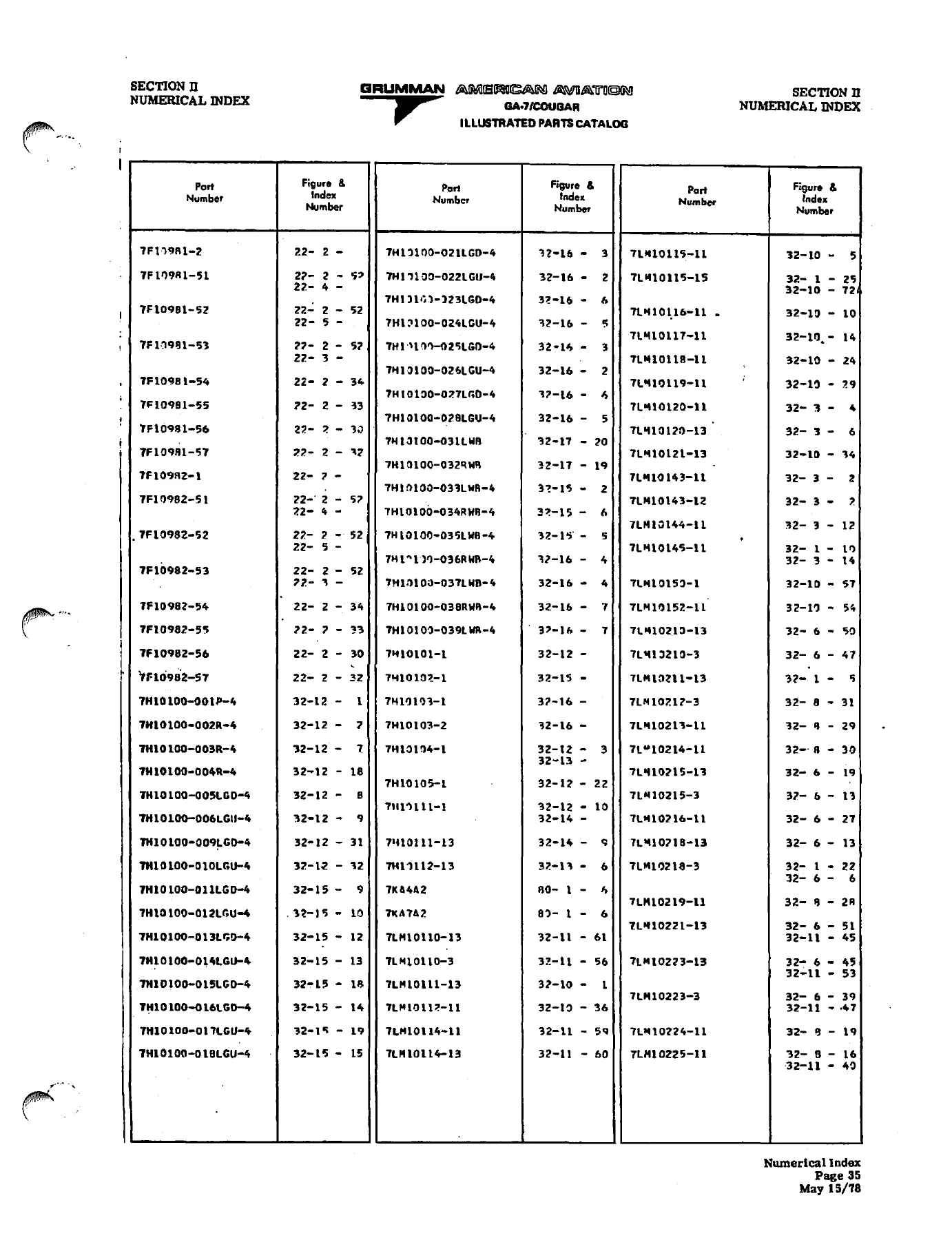
- Section II — Numerical Index
- Alpha-Numerical Master Parts Listing
- Cross-Reference to ATA Chapter, Figure, and Index Callouts
- Standard AN, MS, and NAS Hardware Indexing
- Section III — Detailed Parts Breakdown
- Chapter 11 — Placards and Markings
- Exterior Placards and Decals (Figure 11-1)
- Interior Placards, Limitations, and Warning Markings (Figure 11-2)
- Chapter 12 — Servicing and Support Equipment
- Tow Bar Assembly and Associated Fasteners (Figure 12-1)
- Control Surface Gust Lock Assembly (Figure 12-2)
- Chapter 21 — Air Conditioning (Heating and Ventilation)
- Cabin Heat and Ventilation System Installation — Wing & Nacelle (Figure 21-1)
- Cabin Heat and Ventilation Distribution Installation — Cabin (Figure 21-2)
- Forward Fresh Air System Installation and Louver Routing (Figure 21-3)
- Rear Passenger Vent Installation (Figure 21-4)
- Heat and Ventilation Control Cable Installation and Linkages (Figure 21-5)
- Chapter 22 — Auto Flight
- Century IIB Autopilot Installation with Radio Coupler (Figure 22-1)
- Century III Autopilot Installation with Altitude Hold & Couplers (Figure 22-2)
- Roll Servo Installation and Cable Bridle Assembly (Figure 22-3)
- Pitch Servo Installation and Mounting Structure (Figure 22-4)
- Pitch Trim Servo Installation, Pulleys, and Cable Routing (Figure 22-5)
- Chapter 23 — Communications
- Communications Equipment Options 1 and 3 Installation (Figure 23-1)
- Narco Communications Equipment — COM 120 Transceiver & CP135 Panel (Figure 23-2)
- Collins Communications Equipment — VHF251 Transceiver & AMR350 Panel (Figure 23-3)
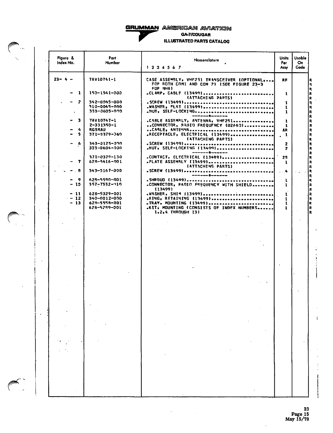
- VHF251 Transceiver Case and Tray Assembly (Figure 23-4)
- King Communications Equipment — KX175B Transceiver & KMA20 Panel (Figure 23-5)
- Emergency Locator Transmitter (ELT) Installation, Whip Antenna & Tray (Figure 23-6)
- Chapter 24 — Electrical Power
- Battery System Installation, Box, Venting & Master Solenoid (Figure 24-1)
- Alternator System Installation, Overvoltage Relays & Voltage Regulators (Figure 24-2)
- External Power System Installation and Ground Service Receptacle (Figure 24-3)
- Chapter 25 — Equipment / Furnishings
- Forward Seat Assembly, Adjustment Tracks & Inertia Reel Belts (Figure 25-1)
- Aft Seat Assembly, Pivot Structure & Safety Restraints (Figure 25-2)
- Adjustable Headrest Assembly (Figure 25-3)
- Child Auxiliary Seat Installation, Framework & Latch Hardware (Figure 25-4)
- Chapter 11 — Placards and Markings
Together, these sections equip maintenance technicians, inspectors, and owners with exact visual schematics and part schedules. Every individual line item lists the manufacturer part number, complete nomenclature, required units per assembly, and structural next-higher-assembly cross-references. This organized presentation eliminates guesswork when replacing worn bushings, electrical relays, ducting clamps, or instrument panel placards on the Grumman American GA-7 Cougar.
Comprehensive Systems & Equipment Breakdown
This catalog provides exhaustive coverage across critical airframe sub-systems. In Chapter 21, the environmental systems are detailed from the exhaust heat shroud manifolds and nacelle dump valves through to cabin distribution tees, mixing boxes, and push-pull control cables. Chapter 22 delivers complete support for both Century IIB and Century III flight control systems, including directional gyros, attitude gyros, radio couplers, amplifier consoles, and the mechanical bridal cable clamps connecting servos to aircraft control runs. Chapter 23 outlines multiple factory avionics configurations, detailing mounting trays, antenna coax leads, and harness connectors for Narco, Collins, and King avionics suites, along with emergency locator transmitters. Electrical generation in Chapter 24 is thoroughly documented with battery box venting, master relay connections, 60-amp alternator brackets, diode heat sinks, and auxiliary ground power receptacles. Interior seating in Chapter 25 is broken down to individual frame weldments, release pins, slide tubes, cushion upholstery, and safety belt inertia reels.
Grumman Part Numbering & Hardware Identification
A distinctive feature of this publication is Section I, which decodes the specialized Grumman American part-numbering system. Technicians can immediately identify part classifications by prefix and suffix codes, distinguishing machined components (M), castings (C), forgings (F), plastic mouldings (P), honeycomb panels (H), and service kits (SB). In addition, Section II provides a massive alpha-numerical cross-index linking standard AN, MS, and NAS aircraft hardware—including structural rivets, castellated nuts, clevis pins, Adel clamps, and O-rings—directly to their respective catalog figures and system installations. A dedicated H4 Federal Supply Code index gives the names and addresses of original component manufacturers, providing invaluable assistance when researching supplier certifications.
IMAGES PREVIEW
Coverage Scope & Publication Details
This 565-page Illustrated Parts Catalog contains the initial October 15, 1977 release pages integrated with the official May 15, 1978 manufacturer revision pages. It provides full coverage of the general aircraft systems, ground handling accessories, environmental control, automatic flight, communications, electrical power generation, and cabin interior installations up through ATA Chapter 25. All illustrations preserve high-contrast engineering lines, exploded mechanical views, and factory assembly sequences as issued by Grumman American Aviation Corporation.
Professional Capability and Instant PDF Delivery
Having the complete Grumman American GA-7 Cougar Illustrated Parts Catalog at your fingertips is vital for maintaining airworthiness, expediting pre-purchase inspections, preparing annual maintenance work orders, and ensuring correct replacement parts are ordered every time. Correct part numbers and exploded views prevent costly ordering errors and unnecessary aircraft downtime. Available as an immediate high-quality PDF download, this digital catalog is fully portable across desktop computers, workshop laptops, and tablets. You can carry it directly into the hangar, zoom into minute hardware assemblies, or print out individual schematics for the workbench without waiting for physical shipping.

Reviews
There are no reviews yet.