
Hartzell 130B Mechanically Actuated Governors Maintenance Manual Rev. 25 December 2020
Original price was: $39.95.$23.95Current price is: $23.95.
Hartzell Propeller Inc. Manual 130B (ATA 61-23-30), Revision 25 dated December 2020, covering overhaul of mechanically actuated governors in the A, B, C, D, E, F, H, S, U, and V series plus T-Drive, accumulator, and pressure control accessories.
Description
Hartzell 130B Mechanically Actuated Governors Maintenance Manual Rev. 25 December 2020
This Hartzell 130B Mechanically Actuated Governors Maintenance Manual Rev. 25 December 2020 is the component maintenance manual used to overhaul Hartzell Propeller Inc. mechanically actuated propeller governors for single-acting propellers on piston-engine aircraft. The publication is identified as Manual No. 130B, ATA 61-23-30. Revision 25 is dated December 2020. The cover lists governor families A-1( ), B-( ), C-( )-( ), D-1-( ), E-( )-( ), F-( )-( ), H-( ), S-( )-( ), U-( )-( ), and V-( )-( ), together with accessories T-Drive C-137-( )B( ), T-Drive C-192-( ), Accumulator 103161, and Pressure Control Unit B-4270.
The Introduction states that the manual has been reviewed and accepted by the FAA and that it contains data approved in a manner acceptable to the FAA administrator. It is written, where possible, in ATA iSpec 2200 format and is intended as the primary source of overhaul information for the applicable Hartzell governor. Procedures are directed at governor repair-station personnel who are trained and experienced with Hartzell Propeller Inc. products. The text expressly notes that it does not give an inexperienced technician enough information to attempt overhaul without supervision. Active Service Bulletins, Service Letters, Service Advisories, and Service Instructions may supersede material printed here and must be consulted.
File Details
- Manual type: Maintenance / overhaul manual (component maintenance manual)
- Brand / manufacturer: Hartzell Propeller Inc., Piqua, Ohio
- Models: Mechanically actuated governors A, B, C, D, E, F, H, S, U, and V series plus listed accessories
- Language: English
- Page count: 892
- File format: PDF
- Document number: Manual No. 130B / ATA 61-23-30
- Revision / date: Revision 25, December 2020
What This Manual Covers
All governors treated in the Hartzell 130B Mechanically Actuated Governors Maintenance Manual Rev. 25 December 2020 are designed for single-acting propellers. Units may meter oil to increase pitch or to decrease pitch, and they are grouped by drive-gear capacity as single, double, or intermediate. Optional hardware includes an unfeathering accumulator, a synchrophaser coil, and a “Z” drive coupling. Models with a Z suffix use drive coupling B-4175 and may be interchanged with the matching non-Z governor (the example given is F-6-22Z in place of F-6-22). A T-drive interface is provided for engines that have no accessory pad for constant-speed control. Additional hardware can be mated to an unmodified governor for propeller pitch reversing.
Table 1, Model Characteristics, classifies each series by oil-flow direction, feathering capability, and drive-gear size. Representative rows include A-1 (decrease pitch, non-feathering, single capacity, T-drive attached), B-2/B-3/B-4 (decrease pitch, feathering, single), C-3 (decrease, feathering) and C-4 (increase, non-feathering), D-1 and E-2/E-5/E-6 (increase, non-feathering), E-3/E-4 (decrease, feathering), E-8 (decrease, feathering, synchrophasing), F-2/F-3/F-4 (increase, non-feathering, double), F-6 (decrease, feathering, double), F-8 (decrease, feathering, double, synchrophasing), H-1 (increase, non-feathering, single), S-1 (increase, non-feathering, intermediate; S-1-( )F is fixed RPM), S-2 (decrease, feathering), S-3 (decrease, feathering, synchrophasing), S-4 (decrease, non-feathering), S-5 (decrease, feathering/unfeathering), S-11 (increase, non-feathering, single), U-3 and U-8 (decrease, feathering/unfeathering; U-8 adds synchrophasing), and V-1 through V-11 with the combinations shown in the table.
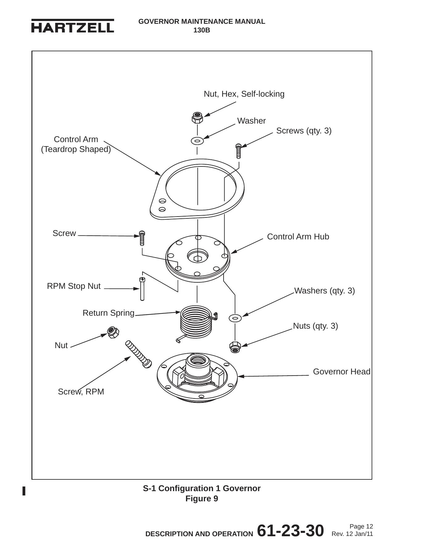
S-series heads appear in several configurations: S-1 Configuration 1 with a teardrop control arm and RPM stop nut; S-1 Configuration 2 and S-4/S-11 Configuration 2 with a one-piece RPM stop; S-1 Configuration 3 (F suffix) with a high-RPM adjust screw acting on the speeder spring; S-2 Configuration 2 (K suffix) with a feather rod in place of the low-RPM stop post; S-3 with a coil assembly; and S-5 with an unfeathering valve and accumulator plumbing.
An early section traces Hartzell model letters back to Hamilton Standard designations such as 1A1, 1Q12, 1M12, 1P12, 1A2G5, 4G8, 4K11, and 4L11. Field units may mix Hamilton Standard and Hartzell-made parts. This book is not a Hamilton Standard governor overhaul manual; it applies only to Hartzell mechanically actuated governors and to Hamilton Standard parts that were used inside those Hartzell units. Parts that meet the overhaul requirements in this manual may be returned to service.
How the Governor Works
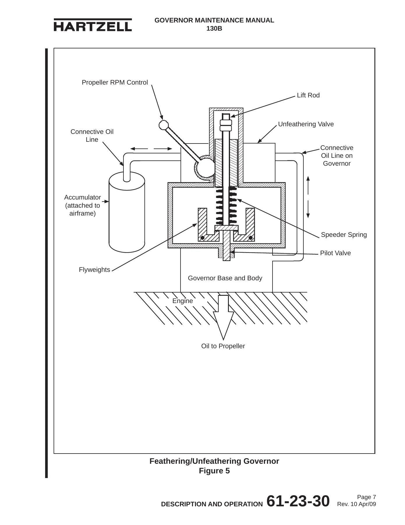
Description and Operation explains the governor as an engine/propeller RPM sensor and high-pressure oil pump. In an onspeed condition the flyweight centrifugal force balances the speeder spring and the pilot valve neither supplies nor drains the propeller cylinder. Underspeed tilts the flyweights inward so the pilot valve meters oil to decrease pitch and raise RPM (on counterweighted installations). Overspeed tilts the flyweights outward so the valve meters oil to increase pitch and lower RPM. Feathering governors add a lift rod that the propeller RPM control uses to force an overspeed drain until the blades feather. Feathering/unfeathering governors add an external hydraulic accumulator and an internal unfeathering valve so stored oil can decrease blade angle, start the propeller windmilling, and support an in-flight restart. Synchronizing and synchrophasing governors add an electrical coil that raises or lowers a rod to change speeder-spring compression on the slave engine so RPM, or RPM and blade phase, match the master propeller.
Model designation is decoded in Figure 18. A sample string such as F-6-35( )LZ identifies model series, application suffix letters (A, B, C, D, F, or K for special attributes), L for left-hand (counterclockwise) rotation when viewed toward the engine pad, and Z for the B-4175 spline drive coupling.
Chapters Covered
- Revision Highlights, Record of Revisions, Record of Temporary Revisions, Service Document List
- Airworthiness Limitations — FAA-approved statement that governor models in this manual currently have no life-limited parts
- Introduction — statement of purpose; item-number and effectivity conventions; Hamilton Standard relationship; reference publications (Manual 159 Application Guide, Manual 165A Illustrated Tool and Equipment Manual, Manual 202A Standard Practices Manual Volumes 1–11, and active service documents); personnel and FAR Part 43 requirements; special tooling (TE prefix) and consumable materials (CM prefix); paint and chemical handling; calendar limits and long-term storage; overhaul definition and HC-SL-61-61Y interval; airworthy versus unairworthy damage; warranty claims; Product Support and Technical Publications contacts; definitions and abbreviations
- Description and Operation — theory of onspeed, underspeed, and overspeed; feathering, unfeathering, synchronizing, and synchrophasing; governor types and Z-drive interchange; S-series head configurations; model designations; Model Characteristics Table 1
- Testing and Fault Isolation — reserved ATA chapter marked not applicable
- Automatic Test Requirements — reserved ATA chapter marked not applicable
- Disassembly — removal from the engine; series-specific tear-down for A-1, B-2/B-3, B-3-4/B-4, C-3, C-4, D-1 (except D-1-8), D-1-8, E-2 through E-8, F-2 through F-8, H, S configurations 1–3 and S-2 through S-5, U-3, U-3-15, U-8, V-1 through V-11; general body, base, and spool work; T-Drive C-137 and C-192; Accumulator 103161; Pressure Control Beta Valve B-4270
- Cleaning — cleaning procedures referenced to Standard Practices Manual 202A where required
- Check — dimensional and condition limits for heads, bases, spools, flyweights, racks, valves, and related parts, including airworthy versus unairworthy damage limits
- Repair — authorized repairs for head units and other components that remain within published limits
- Assembly and Testing — rebuild sequences by series and configuration, RPM-stop installation (including S-1 Configuration 2, S-4 Configuration 1, and S-11 Configuration 2), synchrophasing governor testing, installation back on the engine pad
- Specifications — Table 801 governor specifications (low/feather RPM ±25, high RPM ±10, pressure relief, control-shaft location, internal plug location, control-lever angle, drive ratio/rotation, application notes); Table 802 torque values; Table 803 S-series specifications (Revision 25 adds S-1-90); control-shaft and lever-angle figures
- Special Tools, Fixtures and Equipment — tooling and facility requirements, TE-numbered fixtures
- Illustrated Parts List — exploded assemblies and effectivity-coded parts for A through V series, T-Drives, Accumulator 103161, and Pressure Control Beta Valve B-4270, with an O/H column marking parts that must be replaced at overhaul
Taken as a whole, the Hartzell 130B Mechanically Actuated Governors Maintenance Manual Rev. 25 December 2020 walks a trained shop from pad removal through inspection, repair, rebuild, bench set-up, and reinstallation. Service documents incorporated at the listed revision levels include HC-SB-61-257, HC-SB-61-335, HC-ASB-61-344, HC-SB-61-365, HC-SB-61-372, HC-SL-61-337, and HC-SL-61-341. Temporary revisions through TR-046 are recorded in the front matter of this file.
Overhaul Rules and Limits
Overhaul is defined as periodic disassembly, cleaning, inspection, repair as necessary, reassembly, and testing to Hartzell-approved standards. The interval is based on flight hours and is specified in Service Letter HC-SL-61-61Y. There are no calendar limits on Hartzell Propeller Inc. governors, though stored units require extra inspection before installation using the Packaging and Storage chapter of Manual 202A. Parts not replaced at overhaul are inspected to the Check chapter. Parts that must be replaced are flagged with Y in the Illustrated Parts List O/H column. A warning states that components marked for non-aviation applications must not have their part numbers altered or be used on aviation installations.
Airworthy damage stays inside the Check chapter limits, does not change type design, and need not be repaired before further flight, though prompt repair is recommended. Unairworthy damage exceeds those limits and must be corrected before return to service. The Airworthiness Limitations section, FAA approved 12 March 1998 by the Chicago Aircraft Certification Office ACE-115C, states that governor models affected by this manual currently do not have any life-limited parts.
Specifications and Applications
Table 801 supplies the set-up numbers used with the Assembly and Testing chapter: low/feather RPM, high RPM, pressure-relief band, control-shaft clocking, internal (rotation) plug location, control-lever angle, drive ratio, rotation, and a reference application column. Examples printed on the first specification page include A-1B and A-1C on Continental E-185 and E-225; B-2 on Piper Apache PA-23-150/-160 with Lycoming GO-435/-480; B-3 on Aero Commander 520 and 680; B-3-1 on Helio H-295/H-395 Super Courier; B-4-2 on Piper Comanche 250; B-4-3 on Beech Debonair 35-33/35-A33 with Continental IO-470-J; and C-3/C-4 family units on Pratt & Whitney R-985 installations including Wipaire, Kenmore Air Harbor de Havilland DHC-2 Beaver, and Weatherly. The chapter cautions that aircraft applications are for reference only and may be incomplete; the aircraft Type Certificate Data Sheet is the source for approved propeller/governor combinations. Counterclockwise governors are identified with an approximately 1/2-inch blue dot on the body or head. When the drive ratio is not 1:1, test-stand RPM is the required RPM multiplied by that ratio.
IMAGES PREVIEW
Revision 25 specifically revises the Spool Assembly disassembly section, Cleaning Procedures, Figure 7-53 and the S-1 Configuration 2 / S-4 Configuration 1 / S-11 Configuration 2 assembly text, Testing Synchrophasing Governors, Table 803 to add S-1-90, and the Illustrated Parts List to add S-1-87, S-1-88, S-1-89, S-1-90, S-1-92, and S-1-93.
Companion Publications and Shop Requirements
Work in this Hartzell propeller governor overhaul book is intended to be used with Manual 159 (61-02-59) Application Guide, Manual 165A (61-00-65) Illustrated Tool and Equipment Manual, and Manual 202A (61-01-02) Standard Practices Manual. Tooling callouts use a TE prefix (template TE133 is the example). Consumable materials use a CM prefix (adhesive CM16 is the example) and only the listed materials may be used. Personnel are expected to have the required equipment, training, and certifications demanded by the applicable aviation authority. Maintenance records must meet FAA or equivalent rules; FAR Part 43 is cited for general aviation maintenance requirements. Hartzell Product Support is listed at (937) 778-4379 or (800) 942-7767, fax (937) 778-4215, [email protected], with after-hours AOG message service at (937) 778-4376.
Use This Manual for Overhaul and Return-to-Service Work
With the Hartzell 130B Mechanically Actuated Governors Maintenance Manual Rev. 25 December 2020 a qualified shop can remove a unit from the engine pad, strip head, body, base, flyweight, spool, rack, and drive gear, inspect to published limits, replace the parts marked for overhaul, rebuild by series and S-series head configuration, set low/feather RPM, high RPM, and relief pressure from Tables 801 and 803, torque fasteners from Table 802, test synchrophasing coils where fitted, and reinstall the governor with the correct drive coupling, T-drive, accumulator, or beta valve. Using the printed procedures, damage limits, and specification tables keeps the unit inside type design instead of relying on memory or an older revision. Delivery is an instant PDF after purchase — no printed book to ship — that can be opened on a bench computer, tablet, or phone and printed for the work order.
Reviews
There are no reviews yet.