Hill-Rom Advance Series Bed Service Manual – P1104 P1105 P1115 P1135 P1145 P1155 P1165
$29.95 Original price was: $29.95.$17.95Current price is: $17.95.
Complete Hill-Rom Advance Series Bed Service Manual (man026re) covering models P1104-P1165, with full troubleshooting, theory of operation, removal/replacement procedures, wiring diagrams, and parts lists. Instant PDF download.
Description
Hill-Rom Advance Series Bed Service Manual – Complete Technical Reference for P1104-P1165 Models
This Hill-Rom Advance Series Bed Service Manual (document man026re) is the full factory-style technical reference for the Advance Series hospital bed line, covering product numbers P1104, P1105, P1115, P1135, P1145, P1155, P1165 and their 230-volt counterparts P1106, P1116, P1136, P1146. Spanning 698 pages, this Advance Series Bed Service Manual walks a biomedical or facilities technician through every level of the bed’s mechanical, electrical, and pneumatic systems, from basic function checks to full board-level component replacement.
File Details
- Manual type: Service manual (document man026re, Sixth Edition, Revision E)
- Brand: Hill-Rom
- Models covered: Advance Series Bed β P1104, P1105/P1106, P1115/P1116, P1135/P1136, P1145/P1146, P1155, P1165
- Language: English
- Page count: 698 pages
- File format: PDF, instant digital download
Complete Bookmarks
The complete bookmarks in the βHill-Rom Advance Series Bed Service Manual – P1104 P1105 P1115 P1135 P1145 P1155 P1165β are as follows:
+Chapter 1 Introductionp. 24
+Organizationp. 28
+Typographical Conventionsp. 30
+Introductionp. 31
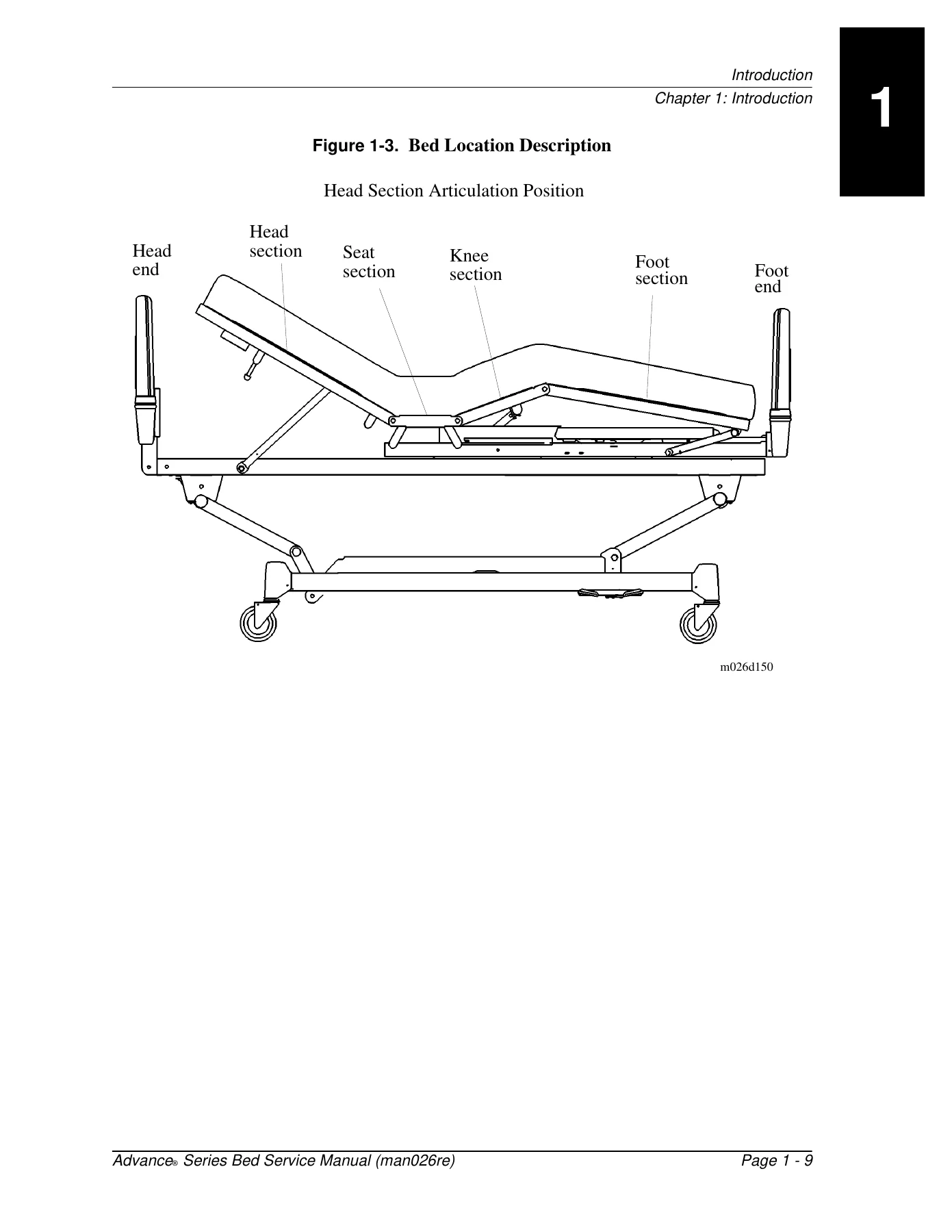
+Bed Positionsp. 31
+Specificationsp. 36
+Physical Descriptionp. 36
+Electrical Descriptionp. 45
+Motorsp. 45
+Hilow (Head and Foot)p. 46
+Model Identificationp. 49
+Siderail Option IDp. 49
+General Operationp. 50
+Manual Operation of Bed (When Electric Power is Not Available)p. 54
+Head Functionp. 54
+Cranking Procedurep. 55
+DynamicAire Sleep Surfacep. 58
+Mattress Componentsp. 58
+Bed Componentsp. 61
+Air Compressorp. 61
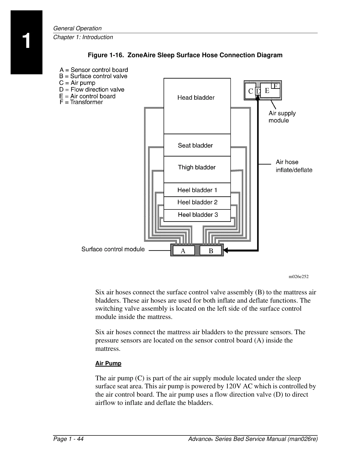
+ZoneAire Sleep Surfacep. 64
+Physical Descriptionp. 64
+Mattress Tickingp. 64
+Mattress Main Air BladdersβUpper and Lowerp. 65
+Air Hosesp. 66
+Footboard Control Panelβ Advance Series Beds with ZoneAire Sleep Surface (Model 1155 and 1165)p. 68
+Power and Siderail Lockout Switchesp. 69
+Modes of Operationp. 70
+Pressure Relief Modep. 71
+Heel Relief Modep. 72
+Bed Scalep. 75
+New Patient Weighingp. 75
+Safety Tipsp. 79
+Warning and Caution Labelsp. 89
+Chapter 2 Troubleshooting Proceduresp. 90
+Getting Startedp. 94
+Service Required LEDp. 100
+Footboard Control Panel Switch/LED Testp. 103
+Air System Self Diagnostic Testp. 106
+Air System Independent Diagnostic Testp. 108
+Soft Resetp. 109
+2.1 Head Hilow Will Not Lowerp. 127
+2.14 DynamicAire Sleep Surface Will Not Operatep. 141
+Four Motor Bed Tester (Not Available)p. 112
+Descriptionp. 112
+Test Unit (Not Available)p. 113
+Four Motor Bed Tester Operationp. 115
+Test Cable to Bedp. 115
+Test Modesp. 117
+Volt-Ohm Meter (VOM)p. 119
+Electrical Functionsp. 119
+SideCom Communication System Testerp. 123
+2.16 ZoneAire Sleep Surface Continuous RunβError Code 2-2p. 145
+2.18 ZoneAire Sleep Surface Sensor EEPROMβError Code 2-4p. 149
+2.19 ZoneAire Sleep Surface Mattress Disconnectedβ Error Code 2-5p. 151
+2.20 ZoneAire Sleep Surface Triac OpenβError Code 2-6p. 156
+2.21 ZoneAire Sleep Surface LON Communication ErrorβError Code 2-7p. 163
+2.23 ZoneAire Sleep Surface Does Not Workp. 167
+2.24 Scale Displayp. 171
+Chapter 3 Theory of Operationp. 174
+Component Locationsp. 178
+Wiring Diagramsp. 184
+ZoneAire Sleep Surface Hardware Theory of Operationp. 208
+Air Control BoardβP/N 44760p. 209
+Sensor Control BoardβP/N 44740p. 213
+ZoneAire Sleep Surface Air Interface Systemp. 217
+ZoneAire Sleep Surface Software Theory of Operationp. 218
+ZoneAire Sleep Surface Operating Modesp. 220
+Mode Transitionp. 225
+Diagnostic Routinesp. 230
+Chapter 4 Removal, Replacement, and Adjustment Proceduresp. 234
+4.1 Head Sectionp. 242
+4.2 Footboard Control Panelp. 244
+4.3 CoverβFoot Endp. 246
+4.4 CoversβHead Endp. 248
+4.5 CoverβSeat Sectionp. 250
+4.6 DynamicAire Sleep Surface Mattressp. 253
+4.7 DynamicAire Sleep Surface P.C. Boardp. 254
+4.8 DynamicAire Sleep Surface CompressorβOld Stylep. 256
+4.9 DynamicAire Sleep Surface CompressorβNew Stylep. 258
+4.10 DynamicAire Sleep Surface Manifoldp. 260
+4.11 DynamicAire Sleep Surface SolenoidβOld Stylep. 262
+4.12 DynamicAire Sleep Surface SolenoidβNew Stylep. 264
+4.13 ZoneAire Sleep Surface Mattressp. 266
+4.14 ZoneAire Sleep Surface Sensor Control Boardp. 267
+4.15 ZoneAire Sleep Surface Sensor Control Valvep. 270
+4.16 ZoneAire Sleep Surface Power Supply P.C. Boardp. 273
+4.17 ZoneAire Sleep Surface Air Control P.C. Boardp. 275
+4.18 ZoneAire Sleep Surface Switching Valve Assemblyp. 278
+4.19 ZoneAire Sleep Surface Transformerp. 280
+4.20 ZoneAire Sleep Surface CompressorβOld Stylep. 282
+4.21 ZoneAire Sleep Surface CompressorβNew Stylep. 284
+4.22 Nurse Control Panel and/or CableβScale Beds Onlyp. 287
+4.23 Nurse Control Panel and/or CableβNon-Scale Beds Onlyp. 290
+4.24 Nurse Control PanelβMembrane Type Footboard (Scale Bed)p. 292
+4.25 Nurse Control PanelβMembrane Type Footboard (Non-Scale Bed)p. 295
+4.26 Nurse Control Panel Switchp. 298
+4.27 Electronics Pan Assemblyp. 301
+4.28 High Voltage Control Boardp. 303
+4.29 Logic Control Boardp. 305
+4.30 Night Light Control Boardp. 307
+4.31 Night Light Bulbp. 309
+4.32 Ribbon Carrier and Cable Assemblyp. 310
+4.33 Head Motorp. 313
+4.34 Hilow Head Motorp. 315
+4.35 Hilow Foot Motorp. 317
+4.36 Knee Motorp. 319
+4.37 Head Screw Assemblyp. 321
+4.38 Hilow Head Screw Assemblyp. 323
+4.39 Head Limit Switchp. 327
+4.40 Hilow Head Limit Switchp. 332
+4.41 Knee Screw Assemblyp. 337
+4.42 Knee Limit Switchp. 340
+4.43 CPR Handlep. 343
+4.44 CPR Limit Switchp. 345
+4.45 Hilow Foot Screw Assemblyp. 347
+4.46 Hilow Foot Limit Switchp. 350
+4.47 Castersp. 354
+4.48 Brake Camp. 356
+4.49 Brake Block Mechanismp. 358
+4.50 Brake Light Switchp. 359
+Removalp. 359
+4.51 Siderail ControlβPatient and Nursep. 361
+Removalp. 361
+4.52 Siderailsp. 364
+Removalp. 364
+Adjustmentp. 365
+4.53 SideCom Communication System Entertainment Controlsp. 367
+Removalp. 367
+4.54 Junction Box P.C. Boardp. 370
+Removalp. 370
+4.55 Testport P.C. Boardp. 372
+Removalp. 372
+4.56 Analog Boardp. 374
+Removalp. 374
+4.57 Scale-Micro Boardp. 376
+Removalp. 376
+4.58 Load Cellp. 381
+Removalp. 381
+4.59 Scalep. 385
+Calibrationp. 385
+Chapter 5 Parts Listp. 388
+Ordering Service Partsp. 394
+Exchange Policyp. 396
+Recommended Spare Partsp. 397
+Base FrameβWithout Scalep. 409
+Base FrameβWith Scalep. 413
+Intermediate Frame Assemblyp. 419
+Electronics Pan Assemblyp. 423
+Retracting Frame Assemblyp. 427
+Upper Frame/Sleep Surface Assemblyp. 429
+DynamicAire Sleep SurfaceβP923CD and P923EDp. 433
+DynamicAire Sleep SurfaceβP923CD03 and P923ED03p. 435
+DynamicAire Sleep Surface Compressor AssemblyβOld Stylep. 437
+DynamicAire Sleep Surface Compressor AssemblyβNew Stylep. 441
+ZoneAire Sleep SurfaceβP1410CA and P1410EAp. 443
+ZoneAire Sleep Surface Power/Air Supply ModuleβOld Stylep. 447
+ZoneAire Sleep Surface Power Supply ModuleβNew Stylep. 451
+Head Panel AssemblyβP4060Ap. 453
+Foot Panel AssemblyβP4061A (P1105 Bed with Toggle Switches)p. 455
+Foot Panel AssemblyβP4061B (P1105 βCβ and βEβ Version Beds with Membrane Switches)p. 457
+Foot Panel AssemblyβP4061C (P1105 βFβ Version Bed with Membrane Switches)p. 461
+Foot Panel AssemblyβP4062A (P1115 Bed with Toggle Switches)p. 465
+Foot Panel AssemblyβP4062B (P1115 βCβ and βEβ Version Beds with Membrane Switches)p. 469
+Foot Panel AssemblyβP4062C (P1115 βFβ Version Bed with Membrane Switches)p. 473
+Foot Panel AssemblyβP4063A (P1135 Bed with Toggle Switches)p. 477
+Foot Panel AssemblyβP4063B (P1135 βCβ and βEβ Version Beds with Membrane Switches)p. 479
+Foot Panel AssemblyβP4063C (P1135 βFβ Version Bed with Membrane Switches)p. 483
+Foot Panel AssemblyβP4064A (P1145 Bed with Toggle Switches)p. 487
+Foot Panel AssemblyβP4064B (P1145 βCβ and βEβ Version Beds with Membrane Switches)p. 491
+Foot Panel AssemblyβP4064C (P1145 βFβ Version Bed with Membrane Switches)p. 495
+FootboardβP4165A (P1155 βCβ and βEβ Version Beds)p. 499
+FootboardβP4165B (P1155 βFβ Version Bed)p. 503
+Footboard with ScaleβP4166A (P1165 βCβ and βEβ Version Beds)p. 507
+Footboard with ScaleβP4166B (P1165 βFβ Version Bed)p. 511
+Foot Siderail Assemblyp. 515
+Head Siderail AssemblyββAβ, βBβ, and βCβ Version Bedsp. 517
+Head Siderail AssemblyββEβ and βFβ Version Bedsp. 523
+Communication Housing AssemblyββAβ, βBβ, and βCβ Version Bedsp. 527
+Communication Housing AssemblyβP/N 61634-01/02 (βEβ and βFβ Version Beds)p. 531
+Knee Drive AssemblyβP/N 43140 and 61701p. 533
+Head Drive Unit AssemblyβP/N 43353, 6200401and 6200402p. 537
+Head Hilow Drive AssemblyβP/N 43278-01 and 6200301p. 541
+Foot Hilow Drive AssemblyβP/N 43278-02 and 62003-02p. 545
+CPR Cable AssemblyβP/N 60945 (βEβ and βFβ Version Beds)p. 549
+High Voltage Power Control BoardβP/N 42822-01/02/03p. 551
+Logic Control BoardβP/N 44158-01/02/06p. 555
+Logic Control BoardβP/N 61410-02 and 6141002 (βEβ and βFβ Version Beds)p. 559
+Night Light Board AssemblyβP/N 43200-01/02p. 563
+Night Light Board Assembly Without ScaleβP/N 48921p. 565
+DynamicAire Sleep Surface Control P.C. Board Assemblyβ P/N 44047p. 567
+ZoneAire Sleep Surface Power Supply BoardβP/N 44719-01/02/03p. 571
+ZoneAire Sleep Surface Sensor Control BoardβP/N 44740p. 573
+ZoneAire Sleep Surface Air Control P.C. Board Assemblyβ P/N 44760-01, 4476002 and 4476003p. 577
+ZoneAire Sleep Surface Membrane Interface P.C. BoardβP/N 44805p. 583
+ZoneAire Sleep Surface Membrane Interface P.C. BoardβP/N 62738p. 587
+ZoneAire Sleep Surface LED P.C. BoardβP/N 44732p. 591
+Junction Box AssemblyβP/N 44647p. 593
+Junction Box AssemblyβP/N 44647p. 595
+Junction Box AssemblyβP/N 45588-02p. 597
+Patient Control PanelβP/N 44124-01/06, P/N 44195-02/03/04/05, and P/N 44196-02/03/04/05p. 599
+Patient Control Panel AssemblyβP/N 44581 and P/N 44635-01/02/03/04/05/06/07/08/09/10/11/12p. 601
+Switch P.C. Board AssemblyβP/N 45016-01/02/03/04/05/06p. 603
+Interface BoardβP/N 44578p. 605
+Outer Control Panel AssemblyβP/N 44668-03/04/05/06p. 607
+Bed Exit P.C. BoardβP/N 44482-01p. 609
+Nurse Control Flex Circuit AssemblyβP/N 43154-01/02/03p. 611
+Scale Micro Board AssemblyβP/N 39506-01p. 613
+Scale Micro Board AssemblyβP/N 61205p. 617
+Scale Display AssemblyβP/N 39452p. 619
+Scale Display AssemblyβP/N 49584p. 621
+Analog Board AssemblyβP/N 39369-01p. 623
+Analog Board AssemblyβP/N 49751p. 625
+Connectors and TerminalsβP.C. Boardsp. 627
+Connectors and TerminalsβMotors and Limitsp. 635
+Siderail Assembly Completep. 636
+Patient Control Unit and Communication Modulep. 637
+Siderail Control Switch Unitsp. 645
+Motor Parts Listp. 647
+VIP Foot Panel Assembliesp. 648
+Chapter 6 General Proceduresp. 650
+Cleaning and Carep. 652
+Component Handlingp. 653
+Preventive Maintenancep. 655
+Preventive Maintenance Schedulep. 655
+Tool and Supply Requirementsp. 662
+Chapter 7 Accessoriesp. 664
+Accessoriesp. 666
+7.1 Fracture Frame Adapter SocketβP847B/P847Cp. 667
+7.2 Roller Bumper AssemblyβP818C03/P818C04p. 668
+7.3 Cane Bumper Assembly CompleteβP284C-48p. 669
+7.4 Trapeze Support AssemblyβP844C-48p. 670
Chapters Covered
- Chapter 1: Introduction β bed positions, physical and electrical specifications, model identification, DynamicAire and ZoneAire sleep surface overviews, bed scale operation, safety tips and warning labels
- Chapter 2: Troubleshooting Procedures β general troubleshooting hints, mechanical/electrical/pneumatic subsystem checks, footboard control panel switch/LED test, air system diagnostics, and dedicated fault trees for Hilow raise/lower failures, head section faults, ZoneAire error codes 2-1 through 2-7, and scale display errors
- Chapter 3: Theory of Operation β component locations, wiring diagrams, ZoneAire hardware theory (power supply board, air control board, sensor control board), ZoneAire software theory and operating modes, control board theory, limit switches
- Chapter 4: Removal, Replacement, and Adjustment Procedures β head section, footboard control panel, covers, DynamicAire and ZoneAire sleep surface components, compressors, load cell, and scale calibration
- Chapter 5: Parts List β base frame, intermediate frame, electronics pan, retracting frame, DynamicAire and ZoneAire sleep surface assemblies, head/foot panel assemblies by version, siderail assemblies, control boards, motor parts
- Chapter 6: General Procedures β cleaning and care, disinfection, component handling, lubrication requirements, preventive maintenance schedules and checklists
- Chapter 7: Accessories
IMAGES PREVIEW
Together these chapters give a technician the full picture of how the Advance Series Bed operates and how to keep it running: from a first-shift diagnostic hint through the exact board part number to order and the torque or calibration step to close the job.
Get the Repairs Right the First Time
With this Hill-Rom Advance Series Bed Service Manual, a technician can accurately diagnose Hilow, head, knee, and foot section motor failures, work through ZoneAire Sleep Surface error codes, calibrate the integrated bed scale, and remove and replace everything from footboard control panels and DynamicAire compressors to logic control boards and siderail assemblies. Correct procedures and torque values protect the patient, the equipment, and the warranty on a piece of hospital equipment that stays in service for years. This Advance Series Bed Service Manual downloads instantly as a PDF after purchase β no shipping wait, no physical copy to misplace. Read it on a laptop, tablet, or phone in the service bay, or print the exact pages you need.

What Our Customers Say
π Related Products
Discover more professional manuals for your equipment

Baxter Gambro AK 98 Dialysis Machine Operator Training Manual - Introduction, Preparation, Treatment & Functions Modules

Nikkiso DBB-07 Hemodialysis Machine Technical Manual (No. 936en-R3, 2012)

Dameca MRI 508 Anaesthesia Machine Service Manual - PDF Download


Reviews
There are no reviews yet.